

Probe an input device(s)'s analog and digital signals
Document your work to the group work page and reflect on your individual page what you learned
Individual assignment:
Measure something: add a sensor to a microcontroller board that you have designed and read it.
***
(1) Welcome to Input Devices Week, this assignment is focused on exploring different sensors both digital and analog.
This time I focused on 3 mini projects.
• Audiovisual alarm system with PIR
• EDM with ultrasonic sensor
• RGB LED with capacitive touch sensor (Approach to the final project)
During the week of electronics design, I made the Guitardino, based on the Samdino by Adrián Torres:
http://fabacademy.org/2020/labs/leon/students/adrian-torres/samdino.html
For the input and output device assignments, I decided to make a new board that allows me to use the largest number of programmable pins, and that also has the possibility of connecting with other boards, thinking about my final project.
So with the advice of my local instructor Iván I designed the JOSAMD 1.0 which is also based on the SAMDINO, and which has an integrated LED, 4 programmable pins, as well as an array of 5 GND and 5V VCD outputs. The sketch:
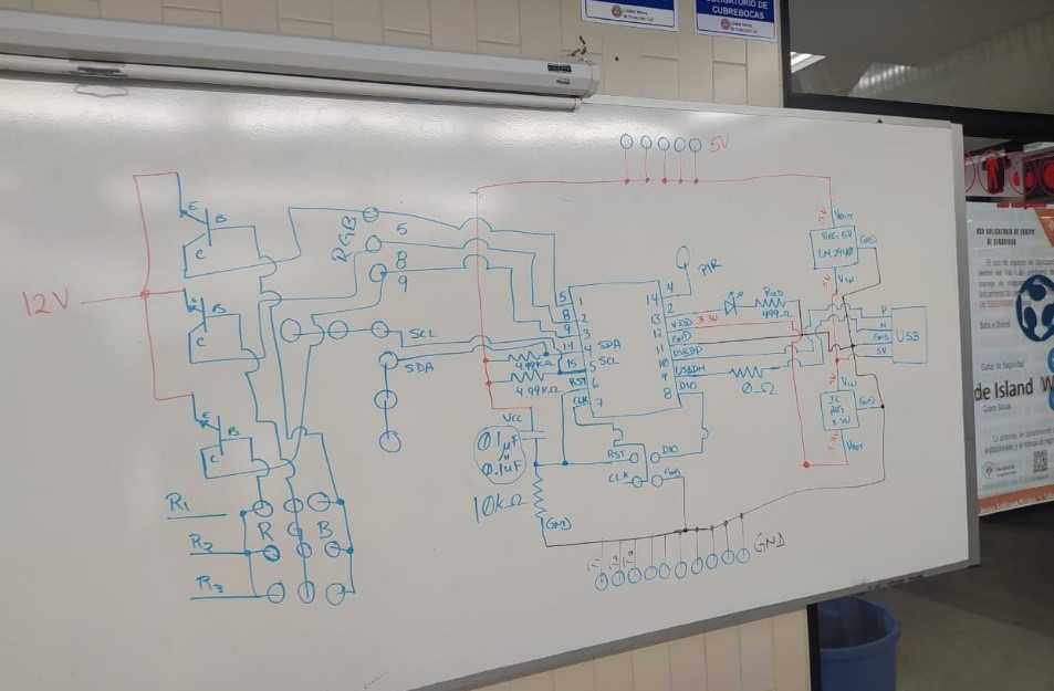
For this process I followed the same workflow as in the electronic design week.
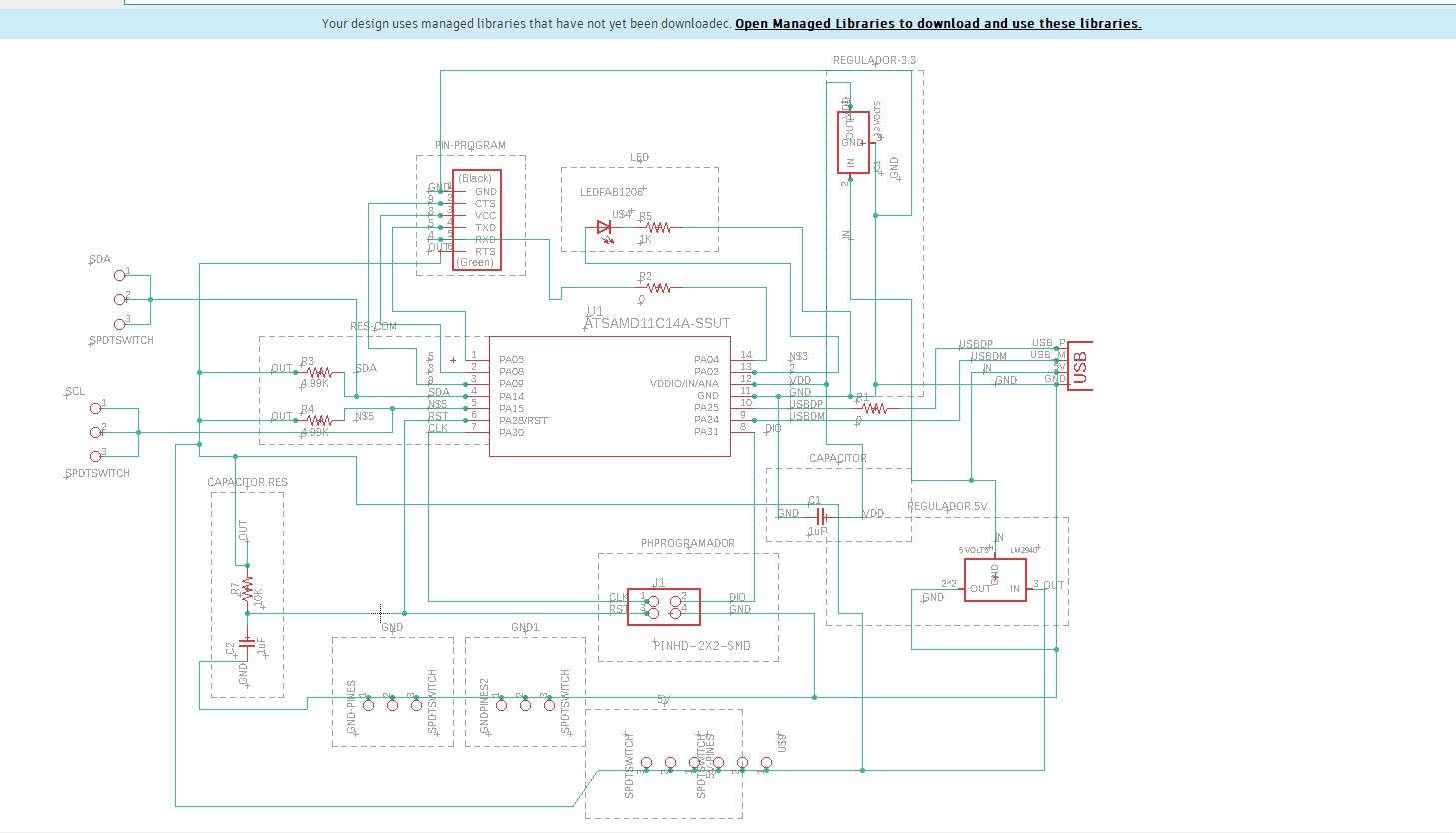
(2) Eagle schematic
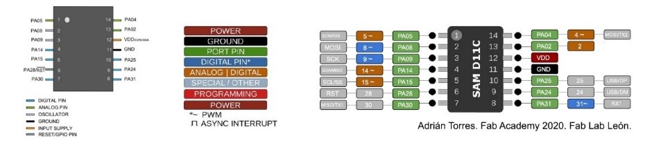
(3) SAMD 11C14A microprocessor:
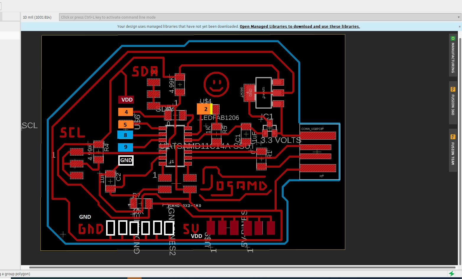
(4) Board:
(5) Trace machining and board cutting.
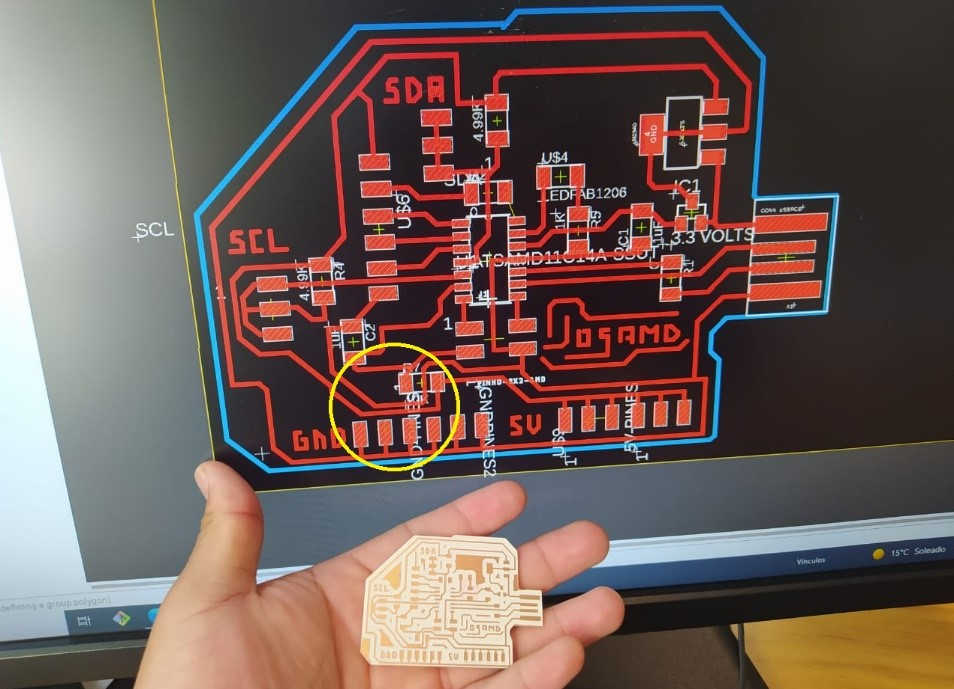
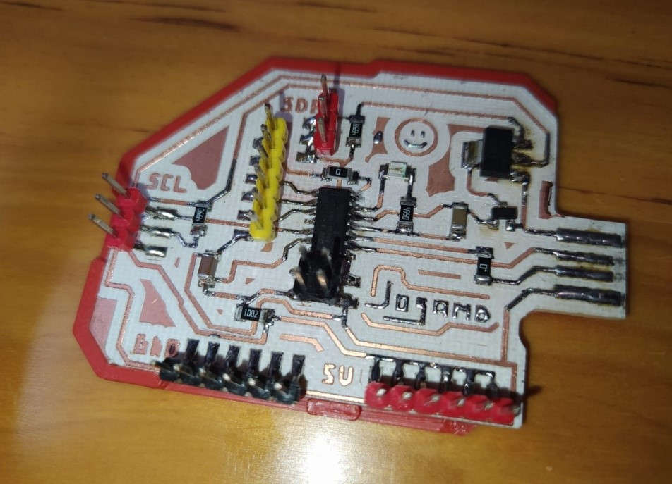
(6) The board had a small design error which I had to correct manually as two posts had been joined.
Board ready for action:
(7) First mini project:
Audiovisual alarm system with PIR
***
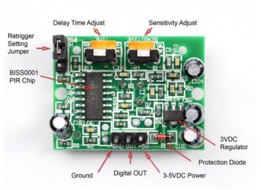
(8) Passive Infrared Sensors (PIR) are devices for motion detection. They are cheap, small, low power, and easy to use. For this reason they are frequently used in toys, home automation applications or security systems.
PIR sensors are based on the measurement of infrared radiation. All bodies (living or not) emit a certain amount of infrared energy, greater the higher its temperature. PIR devices have a pyroelectric sensor capable of capturing this radiation and converting it into an electrical signal.
https://www.luisllamas.es/detector-de-movimiento-con-arduino-y-sensor-pir/
***
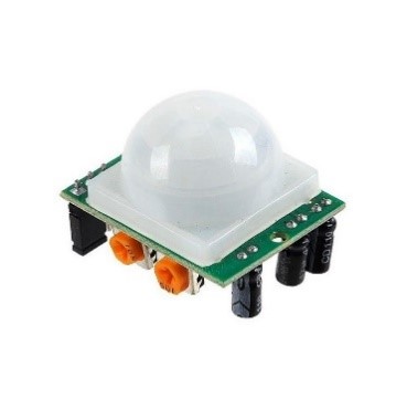
(9) For this exercise I used the PIR module HC-SR501 brand ELEGOO. This device has 3 pins:
•GND
• VDD (5V)
•Sign
(10) As outputs, use the LED built into JOSAMD 1.0 as well as a passive Buzzer module with which to experiment in assigning output devices
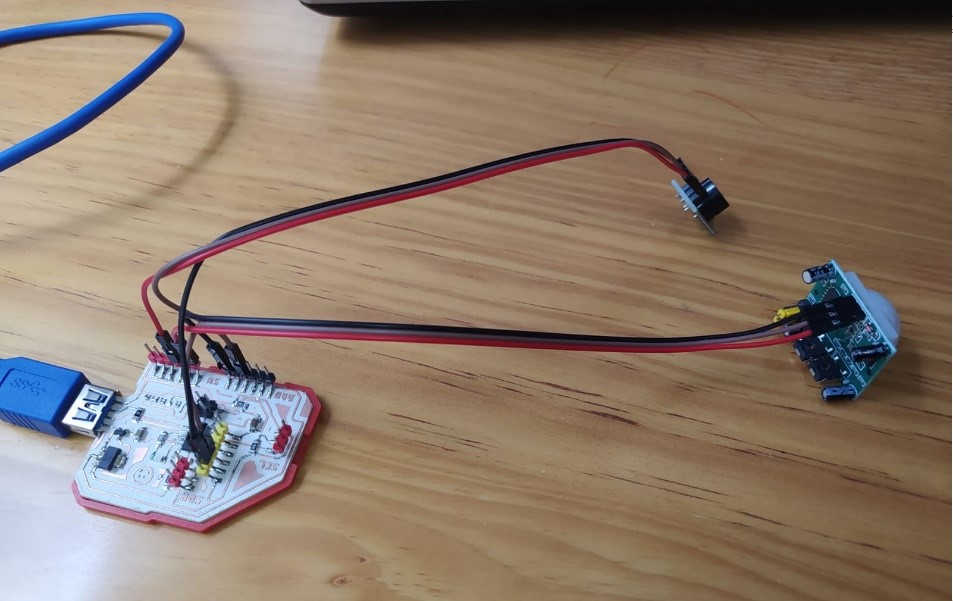 .
.
(11) The objective of the exercise is that the visual (LED) and sound (Buzzer) alarms are activated synchronously when the Motion Sensor detects a body approaching the protected object.
For the programming of the JOSAMD I followed the same workflow that I documented during the week of Embedded programming
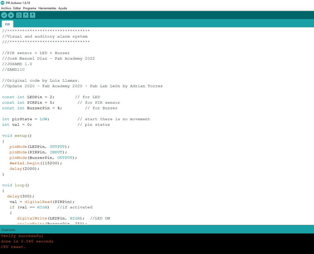
As a starting point I used a code written by Luis Llamas and modified at the time by Adrián Torres, which is designed to observe in the serial monitor when the PIR is high and low, I made the corresponding adjustments integrating the output devices, and I added a conditional to turn on the audio visual stream when the Sensor is high.
PIR sensor + LED + Buzzer
(12) Serial Monitor – Alarm active or inactive?

(13) The result:
(14) EDM with ultrasonic sensor
The second mini project I did was a distance meter with which you can measure the total distance between the sensor and an object (in centimeters)
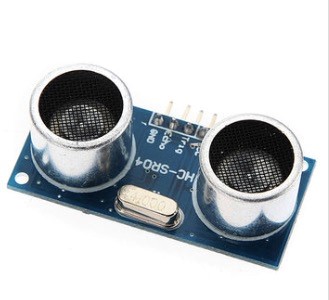
For this project I used the HC-SR04 module, one of the most sold ultrasonic sensors in electronics stores.
****
(15) The HC-SR04 is an ultrasonic distance sensor capable of detecting objects and calculating their distance within a range of 2 to 450 cm. The sensor works by ultrasound and contains all the electronics in charge of making the measurement. Its use is as simple as sending the starting pulse and measuring the width of the return pulse. Very small in size, the HC-SR04 stands out for its low power consumption, high accuracy and low price, which is why it is replacing polaroid sensors in the latest robots.
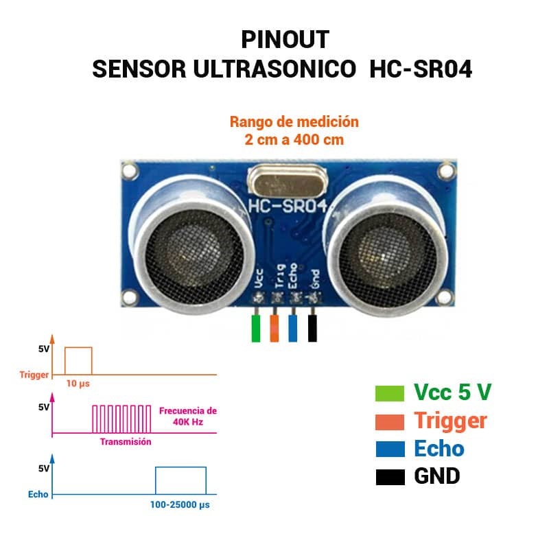
Characteristic
• Supply voltage: 5 Vdc
• Working frequency: 40 KHz
• Maximum range: 4.5m
• Minimum range: 2.0 cm
• Minimum duration of the trigger pulse (TTL level): 10 μS.
• Output echo pulse duration (TTL level): 100-25000 μS.
Connection pins:
• VDC
• Trigger (ultrasound trigger)
• Echo (Ultrasound reception)
•GND
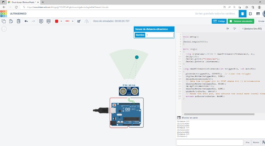
(16) The starting point I used was the code written by Konrad Peschka, I used the Tinkercad simulator to test it, make some modifications and notes that could help other students who want to experiment with this sensor. You can download this and all codes from this assignment at the bottom of the post.
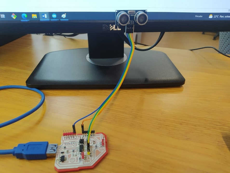
(17) Once it worked in the simulator, I uploaded the code to the JOSAMD and made the necessary connections.
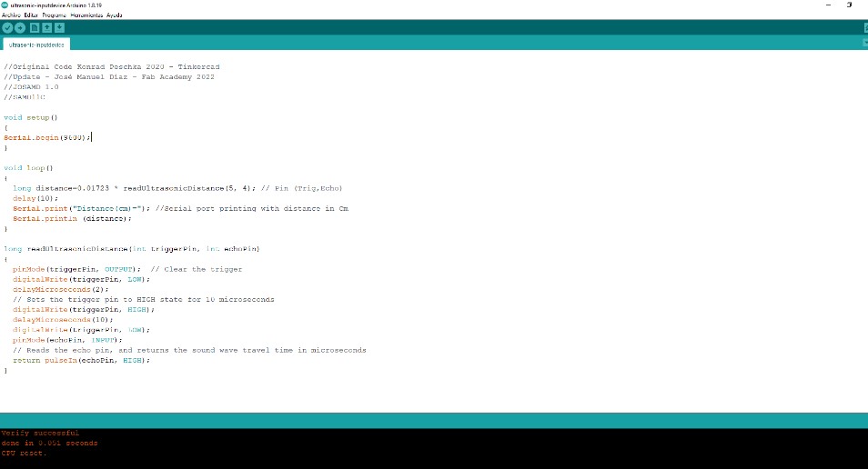
(18) Code uploaded from the Arduino IDE, I used the same workflow as in the embedded programming assignment.
(19) Serial monitor shows the reference distance between object and sensor:

The result:
(20) Mini project 3 – Approach to the final project
My final project will have a lighting system to create different environments, for this I will use RGB leds, in the week of output devices I experimented with an RGB SMD module, on that occasion I used a button to control the lighting sequences, in this week of digital inputs, I will use a touch sensor to offer a better user experience, this device also has the great advantage of being able to detect contact even with sticky or plastic surfaces.
The device I used was a generic touch sensor.
**
A capacitive touch sensor is a device that behaves similar to a push button, but can be activated with little or no pressure.
This type of touch sensor bases its operation on the measurement of the variation of the capacitance. The plate and the human body act as a capacitor and thus form a system that stores an electrical charge.
As the distance decreases, the capacitance increases and the system stores a higher charge. This charge build-up can be detected on the sensor board and generate a digital signal when it exceeds a certain value. This trigger signal can be captured with an Arduino digital input.
The main advantage of this type of sensor is that it does not require physical contact to make the shot, it is enough to bring your finger within 1-5mm of the sensor. For this reason they are called touchless devices.
**
https://www.luisllamas.es/touchless-switch-with-arduino-and-capacitive-sensor/
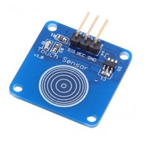
(21) This device has three output pins:
•SIGN
• VDC (5V)
•GND
For this exercise I used the code of the button WITH RGB Led as a base, but I made some improvements, first I put a condition so that the counter restarts at the end of the sequence when it reaches 14, in this way you can keep pressing the sensor and it will continue changing color indefinitely.
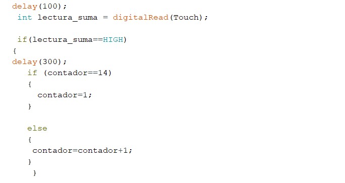
(22) Also incorporate serial monitor printouts to read which color is ON and OFF when the system is powered off.

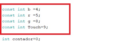
(23) These are the pins I assigned to each device
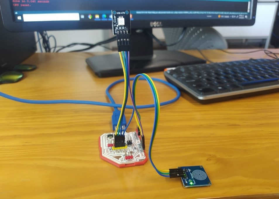
(24) And on the board the connections look like this.
(25) The program running:
![]()

You can download all the assignment files here.
Code:
•Audiovisual alarm system with PIR
•Distance meter with ultrasonic sensor
![]()
Copyright 2022 Jose Manuel Diaz Bello