Week 14: Interface and Application Programming
For this week, we are ask to create application using any platform to interface with our input or output device. We can create interfacing application using many open source platform and I tried some of most popular platform such as Processing and MIT App Inventor.
Instruction:
Individual Assignment:
- write an application that interfaces a user with an input &/or output device that you made
Group Assignment:
- compare as many tool options as possible
Processing
We can use Processing code to create the application in order to interface with the MCU. Processing code uses SerialPort to communicate with controller board.
Download Processing from https://processing.org/download
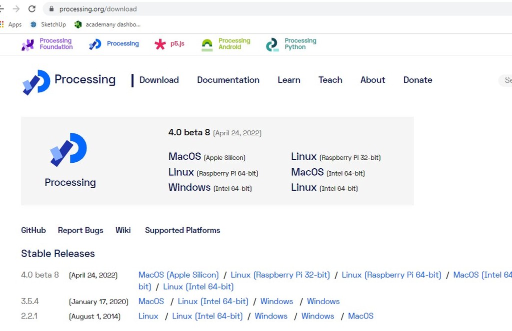
Download as per the system you are using. As I am using window, I downloaded and installed the for the window app.
Once downloaded and installed the application, we can play around with the coding and creating.
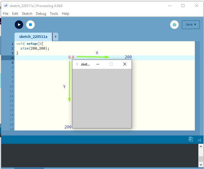
void setup() sets the window of the application that we are making. Unlike other GUI, processing initial (0,0) at the left top corner. First (200) is the X-axis or Width and second (200) is Y-axis or Height of the window.
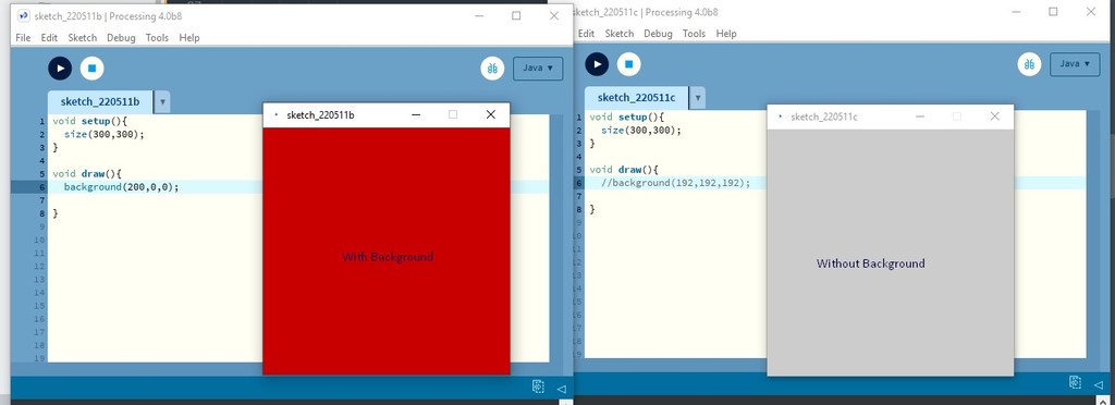
void draw() is like void loop() in arduino code. We can give command or do anything inside the void draw() of the processing. Here I gave backgroud for one and no backgroud for another to compare what it is really for. Usually backgroud is the property of the window that we have created.
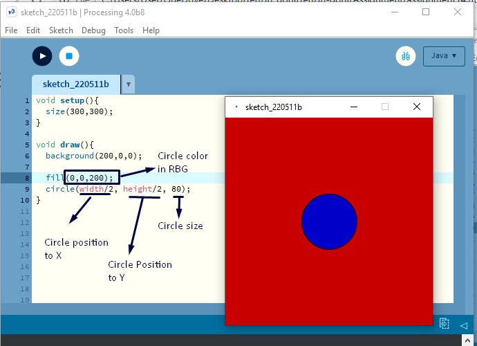
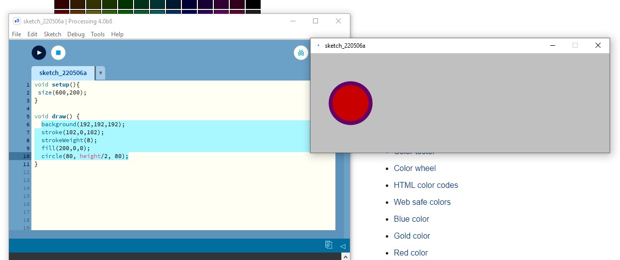
Tried playing with the making of circle. fill(0,0,200); is the fill color for the circle we create. circle(width/2, height/2, 80); creates the circle of diameter in 80px. width/2 and height/2 are the position of the circle to X-axis and Y-axis.
As I created the window of 300 px by 300px, position to X will be 150 and Y will be 150 too.
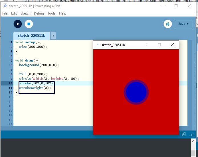
stroke is the boarder around the circle we created. strokeWeight(8); is the thickness of the boarder and stroke(102,0,102); is the color of boarder in RGB.
Processing and Controller
Processing can communicate with controller through the serial port. We need to interface the interactive button with serial port and send serial message through it to communicte with MCU.
Controller can read the serial message coming through serial port and execute the controling as per the command received.
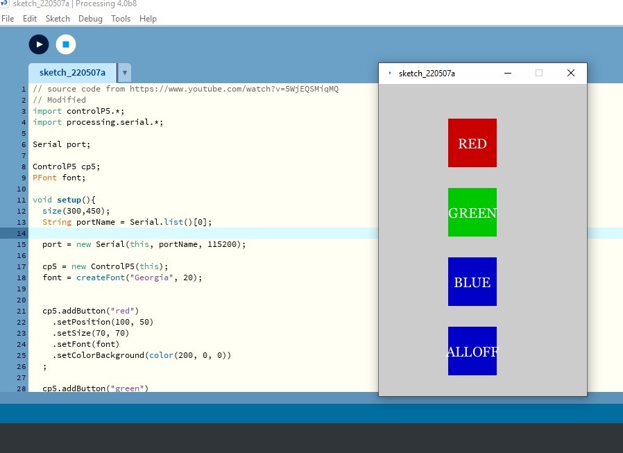
For this assignment I took the reference from https://www.youtube.com/watch?v=5WjEQSMiqMQ.
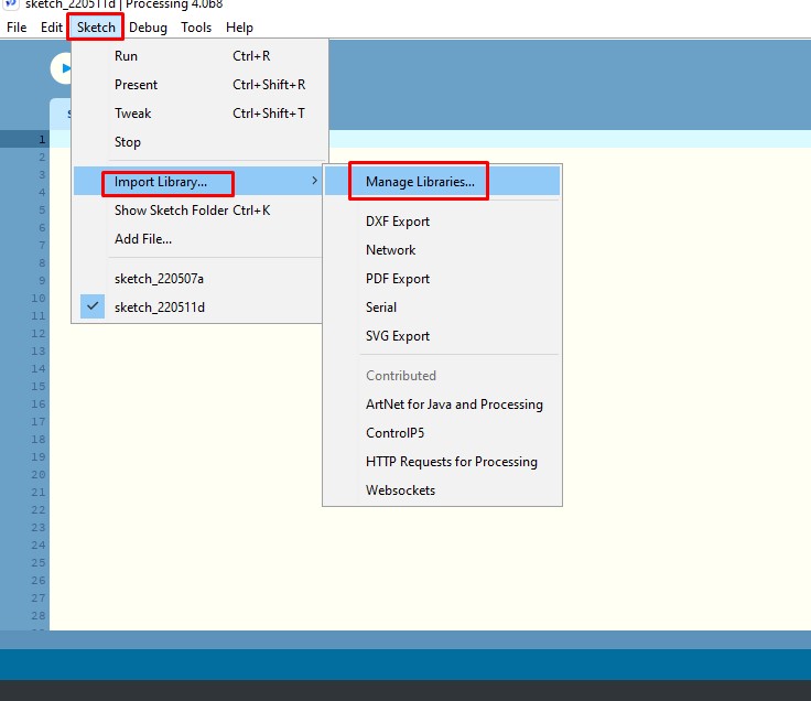
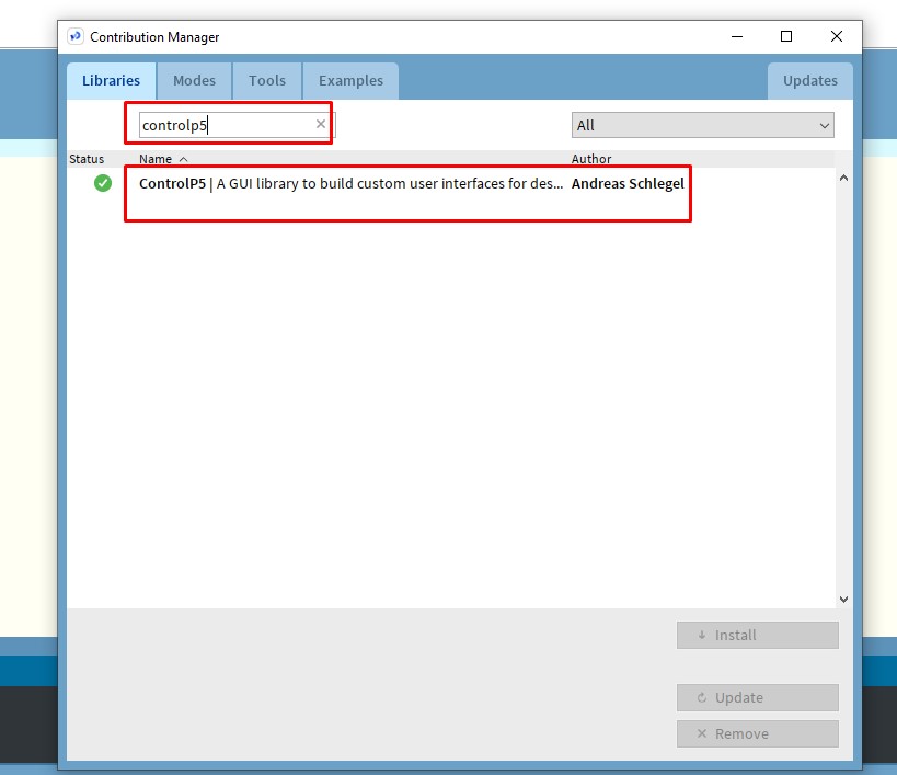
I required to add button to communicate with controller. So, I added the library of ControlP5 of processing. ControlP5 is a GUI and controller library that can be used in application.
We can install the library as shown in the above image.
I modified the code as I required, find my modified code at the end.
port = new Serial(this, "COM3", 9600);
Usually the 'port' is define as above in most program code, but sometimes this gives problem where it does not properly get the desire 'COM Port'. So, with the instruction from my instructor, I changed the port code as below.
  String portName = Serial.list()[0];
  port = new Serial(this, portName, 115200);
Serial.list()[0] string selects the first COM port availble, I used [0] as I was having only one available. If your desired COM port is in second list in the available port, use [1] and so on.
	  cp5.addButton("red")
	    .setPosition(100, 50)
	    .setSize(70, 70)
	    .setFont(font)
	    .setColorBackground(color(200, 0, 0))
	  ;
Adding of button code is made much easier using controlP5 library and above code adds red button to my window.
Once one button is added, it is easier to add rest of the button. Just change position of the button and background color of the button.
	void red(){
	  port.write('r');
	}
	void green(){
	  port.write('g');
	}
	void blue(){
	  port.write('b');
	}
	void alloff(){
	  port.write('o');
	}
Since I have created button as red, green, blue and alloff, I made it to send serial 'r' for red button, 'g' for green button, 'b' for blue and 'o' for alloff.
Arduino ide Code for controller
Now we require the code for our controller. First I tried with arduino and than with esp32 wroom board of my project. Once the code work well with arduino, it works well with the esp32 board too.
Arduino code too I edited from the surce code from https://www.hackster.io/hardikrathod/control-arduino-using-gui-arduino-processing-2c9c6c and edit it to my requirement.
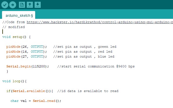
I changed pin number as my required and removed some unwanted code. I hadn't had much to edit until I got severe functioning problem. This code is actually for individual led but I was using commom anode RGB led instead of individual led.
As shown in the video above, it wasn't functioning well. When I click on the red button, it glowed green, on green button glowed blue and on blue button it turn off.
It took me a whole lot of time in debugging. At last with the consultation of instructor, we found out that, actually to turn on the led with the common anode requires the GPIO pin to get LOW and with the GPIO pin to HIGH, turns off the led. So, we needed to program in such a way that GPIO pin get LOW when port receives the serial reading from the Processing app.
    if(val == 'r'){       //if r received
      alloff();
      digitalWrite(14, LOW); //turn on red led
      Serial.println("Red");
      }
    if(val == 'g'){       //if g received
      alloff();
      digitalWrite(26, LOW); //turn on green led
      Serial.println("Green");
      }
    if(val == 'b'){       //if b received
      alloff();
      digitalWrite(27, LOW); //turn on blue led
      Serial.println("Blue");
    }
    if(val == 'o'){       //if o received
      alloff();
    }
So, we modified the code as above, where when serial read is 'r', red pin gets lows and same with other led pins.
When leds are individual we can glow them all at a time without closing the other, but using the RGB led, when glow together over powers some color by other color, so, distinction becomes less. For that, when the serial reads something, I let to turn off the other pins and turn on the specifics pin only using the 'alloff' function as below.
	  void alloff(){
	      digitalWrite(26, HIGH); //turn off all led
	      digitalWrite(14, HIGH);
	      digitalWrite(27, HIGH);
	  }
Find my edited code at the end of the assignment.
With the chenge in the codes, we got it working well
MIT App Inventor and Controller:
I wanted to try controlling RGB led from net using IP address created by esp instead of using serial port for communication. Unluckily, I couldn't find any tutorials doing that and I couldn't get the clue how processing app could communication through IP, so I tried that on MIT App Inventor.
In order to create the app in MIT App Inventor, I refered to https://randomnerdtutorials.com/esp8266-controlled-with-android-app-mit-app-inventor/.
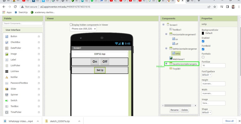
This is on the designer page where I added three horizontal and kept one hidden, because I want it to be hidden during normal and wants only to show when I click on set ip button.
I also added webviewer and tinyDB which I will require to connect to web and store added IP.
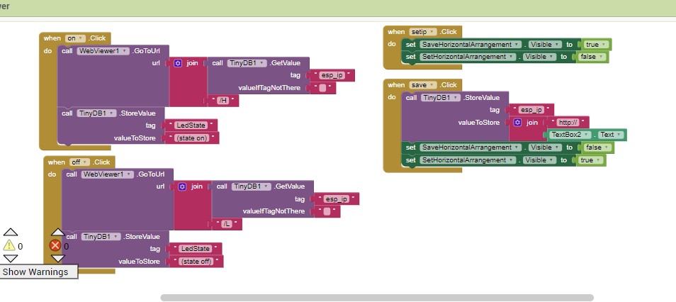
This is simple block code I made to control led.
This block code I created with accordance to the ESP web Blink Example code where we can turn on and off the led from web.
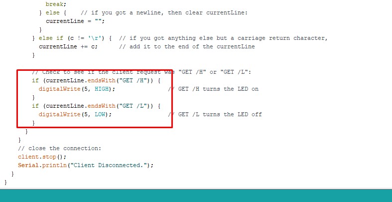
According to the code, it should receive '/H' to turn the led on and '/L' to turn off the led, so, I need to send command of '/H' and '/L' from the app to turn on and off respectively.
So, in the block code, I gave '/H' when tap the ON button and '/L' when click on the OFF button.
Find .aia file of my block code under the assignment file at the end of the assignment. For ESP code, I directly used the example code of SimpleWiFiServer.
Reference
- Processing Download link: https://processing.org/download
- Processing tutorial: https://www.youtube.com/watch?v=5WjEQSMiqMQ
- MIT App Inventor: https://appinventor.mit.edu/
- MIT App inventor for ESP32 referal https://randomnerdtutorials.com/esp8266-controlled-with-android-app-mit-app-inventor/