
Embedded Programming
Group Assignment
Group Assignment:
compare the performance and development workflows for other architectures.
The group work that our group has done can be seen here
Individual Assignment:
read the data sheet for your microcontroller
use your programmer to program your board to do something
extra credit: try other programming languages and development environments
Data Sheet ATtiny44a
Micro-Controller
According to wikipedia a microcontroller A microcontroller (MCU for microcontroller unit) is a small computer on a single metal-oxide-semiconductor (MOS) integrated circuit (IC) chip. A microcontroller contains one or more CPUs (processor cores) along with memory and programmable input/output peripherals. We can imagine it as micro-computer on aingle integrated circuit. According to abhinav-ajith A microcontroller contains one or more CPUs (processor cores) along with memory and programmable input/output peripherals. Program memory in the form of ferroelectric RAM, NOR flash or OTP ROM is also often included on chip, as well as a small amount of RAM. Microcontrollers are designed for embedded applications, in contrast to the microprocessors used in personal computers or other general purpose applications consisting of various discrete chips like ADC(analog to digital converter),DAC [Digital-to-Analog Converter]
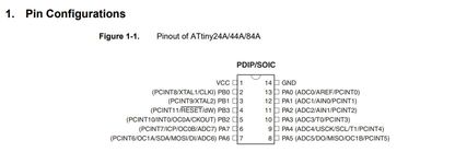
I used ATtiny44a for my eco_board design. Therefore, I would like to present my understanding from the datasheet I referred. The datasheet for ATtiny44a can be downloaded from http://academy.cba.mit.edu/a ATtiny44a is a 8 bit AVR microcontroller with 4k in-system Programmable flash. It has 256 bytes of In-system Programmable EEPROM and internal SRAM. It is a 14-pin SOIC (Small Outline Integrated Circuit) with 12 programmable I/O lines which can be operated at 1.8-5.5V. Power consumption is at the max of 1.8V.
PIN configuration can is as seen below whereby VCC is a supply voltage, GND is ground, Port B (P3: P30) and Port A (PA7: PA0)is a 4-bit bi-directional I/O port with internal pull-up resistors. RESET for this microcontroller is on PB3.
Programming ATtiny44a with Arduino IDE
A friend of mine gave me a self explainatory tutorial to install a driver of FabISP to my windows device from learn.adafruit.com
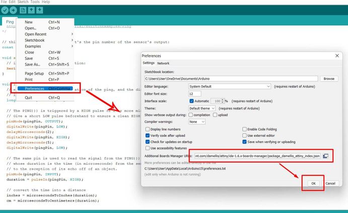
I installed the driver. One problem with my FabISP is that it do not give power supply to my board as I blew up the fuse when I programmed it. Therefore, I have to use Aruino Uno board to supply VCC and GND line to my FabISP. Arduino IDE dp not support ATtiny 84/44/24, therefore, the first step is to add the board directories to the arduino IDE.
Open Arduino --> File --> Go to Preferences and paste this url: and then press Ok.
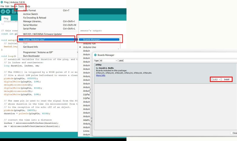
Next step is to set up the boards. If you don't find your boards already set up, go to boards manager following the steps:
Tools --> Board Manager. In the search box, search for ATtiny and install the board. (Mine is already installed).
Next, set up the tools. Tools ---> Board ---> ATtiny Microcontrollers ---> ATtiny24/44/84
A processor tab will be shown under the tools. Then again, go to Tools ---> Processor ---> ATtiny44
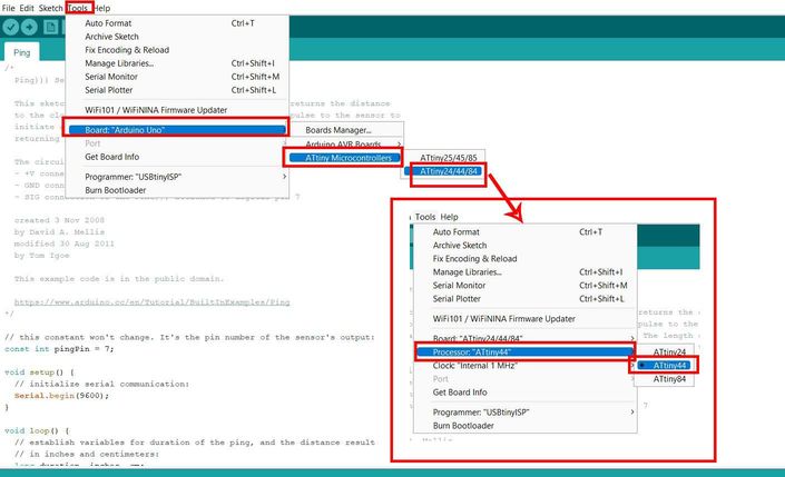
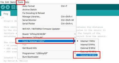
Next step is to set up clock under the tools. Go to Tools --->Clock "Internal 1 MHz" ---> Choose External 20 MHz.
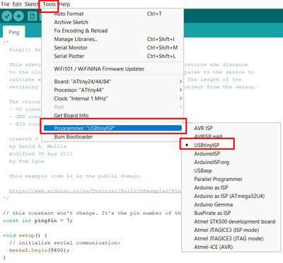
After that choose a programmer. We are almost done setting up a IDE. Go to Tools ---> Programmer --> and choose USBtinyISP
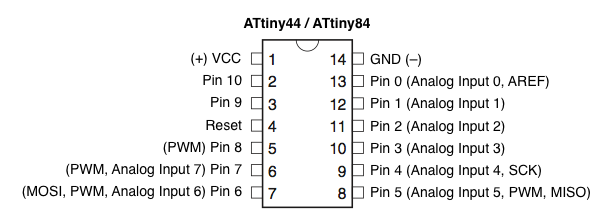
With this we are done setting up Arduino IDE for ATtiny Micro-Controllers. Now we need to learn about the ATtiny44 Pinouts. This is to familiarize onself to pins and how it is interpreted in arduino IDE. Folloing image can clearly teach about the pins in microcontroller and its equivalent in arduino IDE. A detailed explaination can be seen here
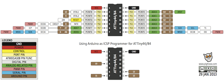
A simpler version can be viewed here: It means that the PIN number 7 in our ATtiny44 microcontroller is Pin 6 in Arduino IDE, etc...
Embedded Programming: Arduino Code: LED Blink
In order to program my board, first I need to check my board once again. The task I am going to perform is burn LED as a starter. My LED is
connected to Pin 5 which is Pin 8 in Arduino. Therefore, I used examples in arduino to burn my LED.
Go to File ---> Examples ---> Basics---Blink.
The code I used are as follows:
                                    void setup() {
                                        // initialize digital pin LED_BUILTIN as an output.  pinMode(8, OUTPUT);
                                      }

                                      // the loop function runs over and over again forever
                                      void loop() {
                                        digitalWrite(8, HIGH);   // turn the LED on (HIGH is the voltage level)
                                        delay(1000);                       // wait for a second
                                        digitalWrite(8, LOW);    // turn the LED off by making the voltage LOW
                                        delay(1000);                       // wait for a second
                                      }
The time for High and low is kept as 1000 which 1000 miliseconds or 1 second. The result is as shown below: When the time for High is changed to (150) the resultant can also be seen here.
Embedded Programming: Arduino Code: Button
In order to use the button code, go to File ---> Examples ---> Digital ---> Button. I have my button on Pin 6 which is Pin 7 in arduino.
                                    const int buttonPin = 7;     // the number of the pushbutton pin
                                    const int ledPin =  8;      // the number of the LED pin

                                    // variables will change:
                                    int buttonState = 0;         // variable for reading the pushbutton status

                                    void setup() {
                                    // initialize the LED pin as an output:
                                    pinMode(ledPin, OUTPUT);
                                    // initialize the pushbutton pin as an input:
                                    pinMode(buttonPin, INPUT);
                                    }

                                    void loop() {
                                    // read the state of the pushbutton value:
                                    buttonState = digitalRead(buttonPin);

                                    // check if the pushbutton is pressed. If it is, the buttonState is HIGH:
                                    if (buttonState == HIGH) {
                                        // turn LED on:
                                        digitalWrite(ledPin, HIGH);
                                    } else {
                                        // turn LED off:
                                        digitalWrite(ledPin, LOW);
                                    }
                                    }
The result is as shown below: