
Computer-Controlled Machining
Group Assignment
Group Assignment:
do your lab's safety training
test runout, alignment, fixturing, speeds, feeds, materials, and toolpaths for your machine.
The group work that our group has done can be seen here
Individual Assignment:
make (design+mill+assemble) something big (~meter-scale)
extra credit: don't use fasteners or glue
extra credit: include curved surfaces
Make Something Big
I have shifted my place from the south of Bhutan to Thimphu, nearby my lab. As it is a temporary resetllement, I don't have any furnitures in my new home. Therefore, I am going to design a low table to be used in my living room.
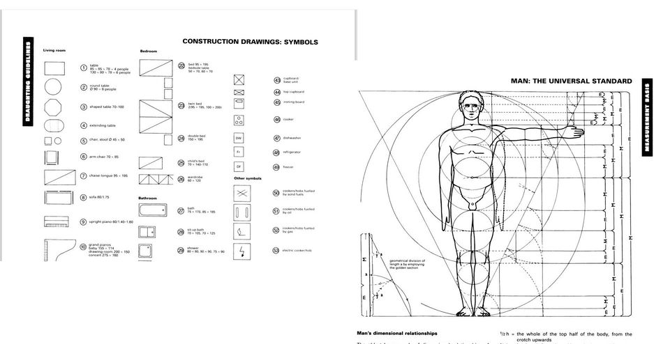
I reviewed some design standards for furniture design using anthroprometrics studies in Neufert, a data book for Architects.
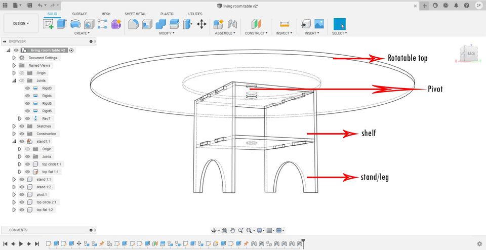
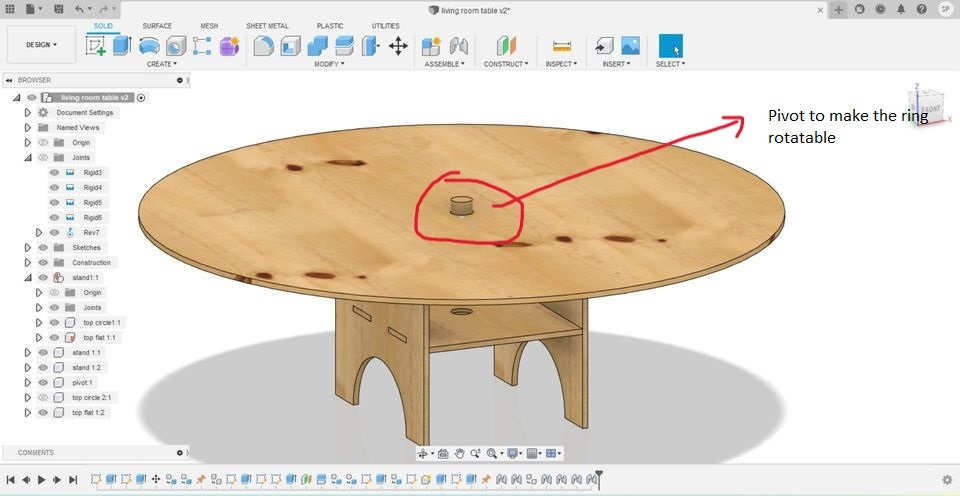
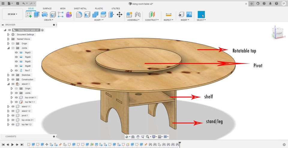
I used parametric design to design the furniture using fusion360. I want to make a table with a rotatable top.
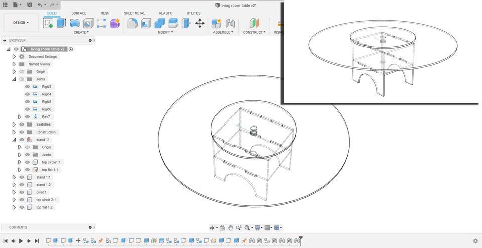
Some photos of my designs can be seen here.
The base is designed to avoid any nails or glues.
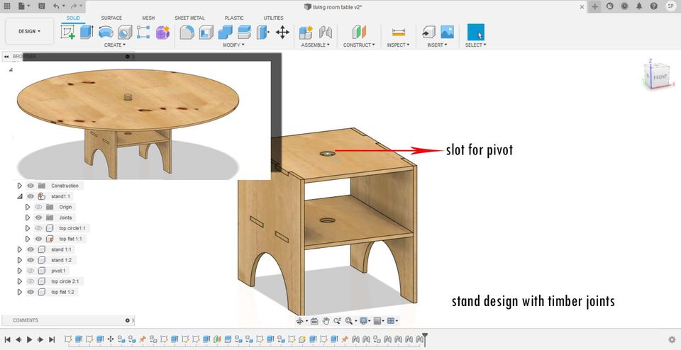
The first layer of table can be rotated, so that you can share meals or items just by rotating the table, instead of picking it up. Pivot is located just below the arrow indicated as the pivot.
Final, views can be seen as shown here.
The animation video of design and assembling of this table can be seen below:
In the asia review, I got a comment from the regional instructors that my design will not be usable as it may topple off as the base to top ratio is not maintained. Therefore, I changed my design.
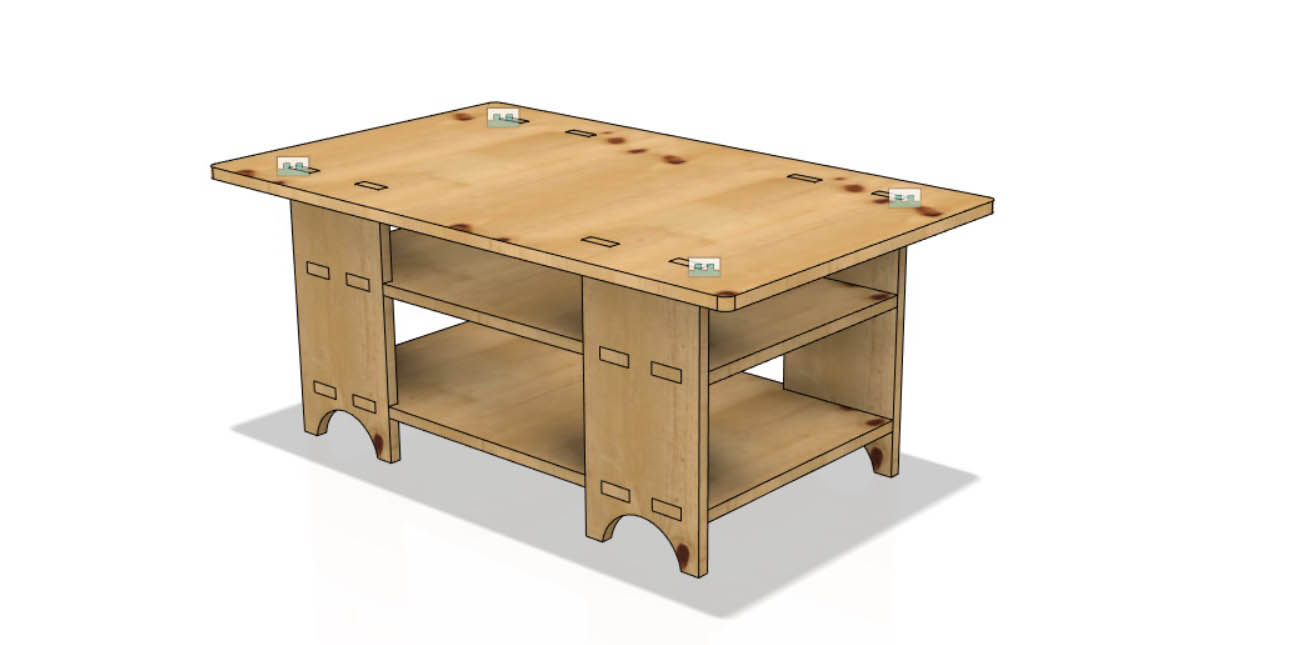
I kept a same theme, i.e., a table for my living room. The designed as follows:
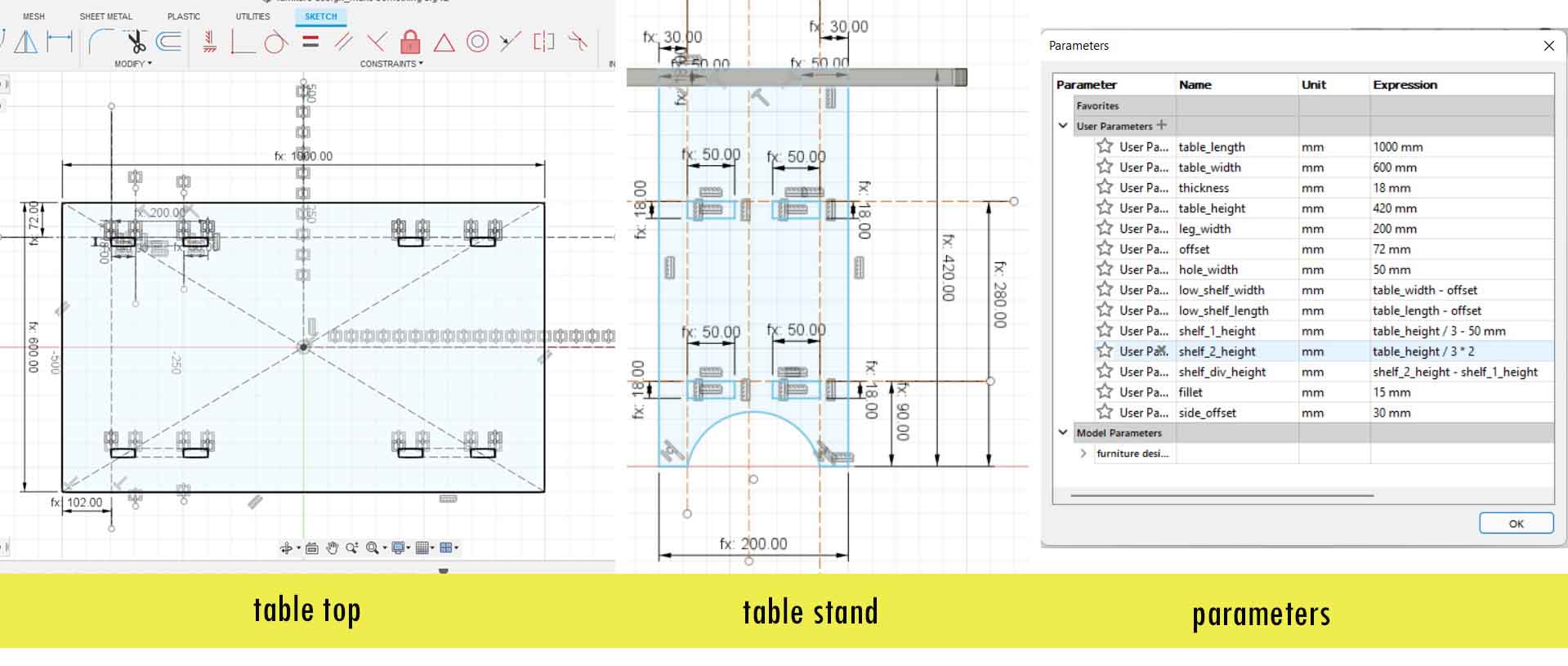
The final design comprised of 4 stand, two horizontal elements which will act as a shelf and a table top. The height is 420mm and the size of
the table top is 600mmX100mm.
After the design is complete, I saved .dwg files from my drawings and the files were sent to a CNC Machine Room.
CNC Machine
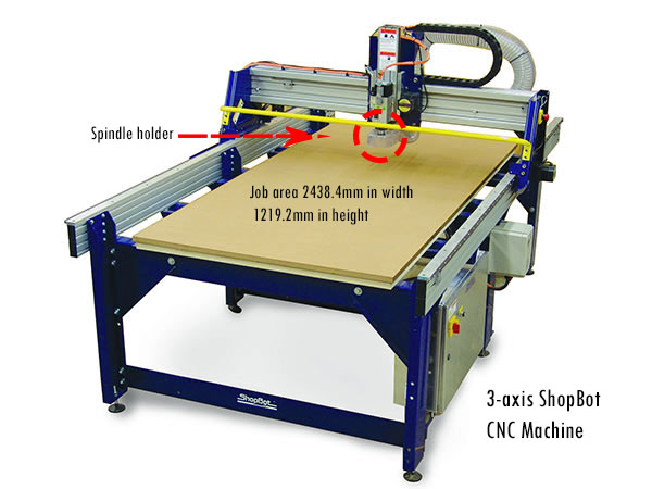
My lab has a ShopBot PRSalpha CNC machine. Details of this machine can be seen here
shopbottools.com. CNC is a abbreviated
form of Computerized-Numerical-Controlled Machine.
The tool uses an advanced technology for CNC cutting, drilling, carving and machining. As per the
the website, its series tools deliver rapid transit speed of 1800 inches/min and cutting speed of
600 inches/min.
You can also refer QuickStartGuidePRSAlphaStandard.pdf The pdf has all the details about CNC and its operation.
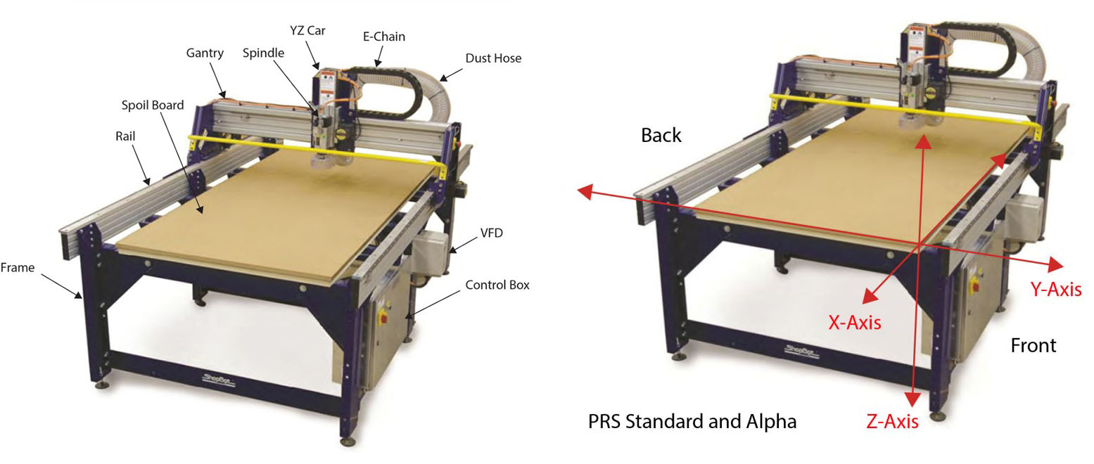
Spindles & Routers is a rotatory part of the machine and is often referred to the shaft at the center of the rotating axis. You can refer here for details. ShopBots can be fitted with a variety of tools/heads for cutting and machining. We have the most common tools for standard woodworking router but it can also be fitted with a high-frequency industrial spindle. These tools are similar in principle; basically a motor for turning a cutting bit at high speeds.
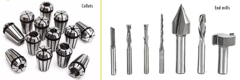
Collets and Endmills
Collets are a type of chuck and it works in conjunction with a spindle. Collet chucks allow for a consistent gripping force when machining. It is the main component which holds the end mills or cutting tools to spindle. Therefore, it handles grip and speed.
Endmill on the other hand, is a main cutting and carving tools of CNC. End mills have cutting surfaces called flutes which are of two to four flutes. Generally, fewer flutes evacuate more chips from your material, keeping the bit cool. However, more flutes produce a finer edge finish.
CNC Cutting and Assembly
I could not visit my lab to carry out hands-on experiment since the lab is closed as we are under lockdown due to surge in covid-19 community cases. I hope to carry out the assignment as soon as the lockdown opens or as soon as I can visit the lab.
Finally, lockdown has been lifted and I could visit my lab to carry out my works with CNC machine. For CNC,
we use two softwares, one to create a machine file path and other to control the CNC machine. Aspire10.512 is used to create a machine toolpath.
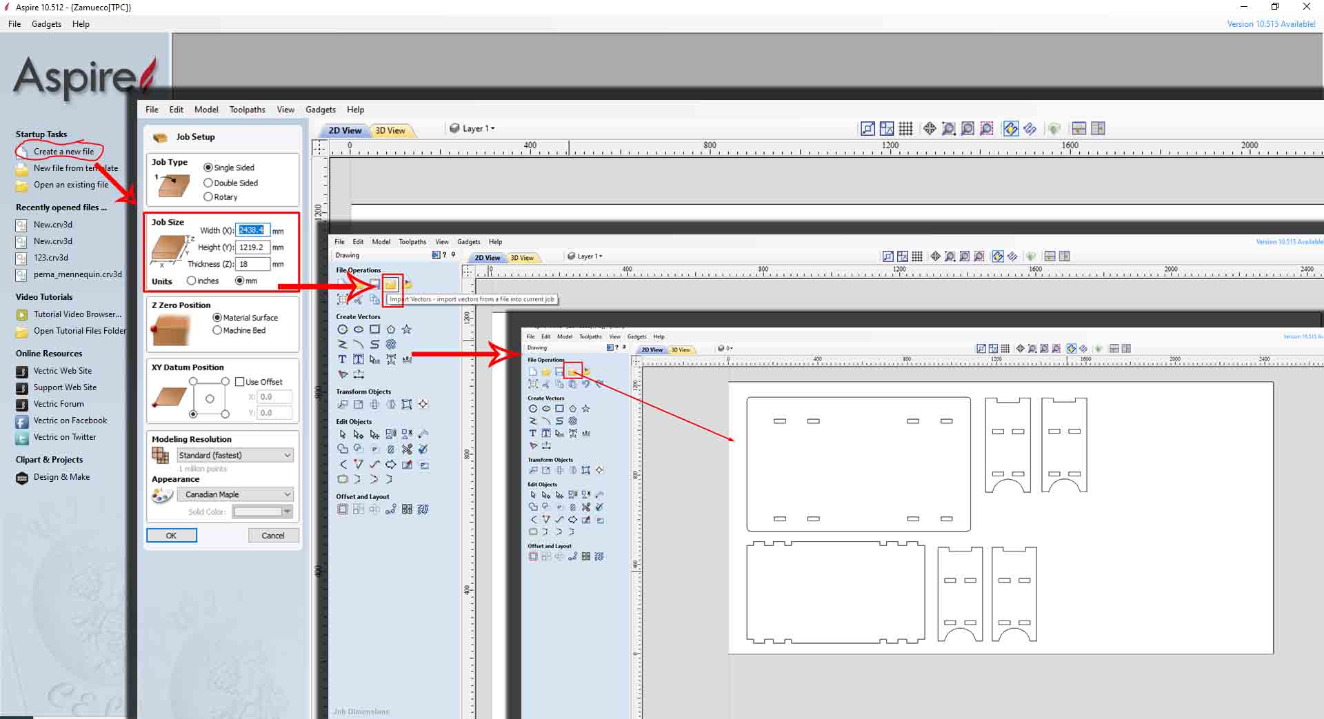
Firstly, you open the softare ---> Create a new File
A job setup windows will pop up. Give a material size. We were provided 8X4 inch and 8mm thick plyboard by the lab. Therefore, my job size
is 2438.4mm in width (Y-axis), 1219.2mm in height (Y-axis) and 18mm in thickness (Z-axis). The click -->Ok.
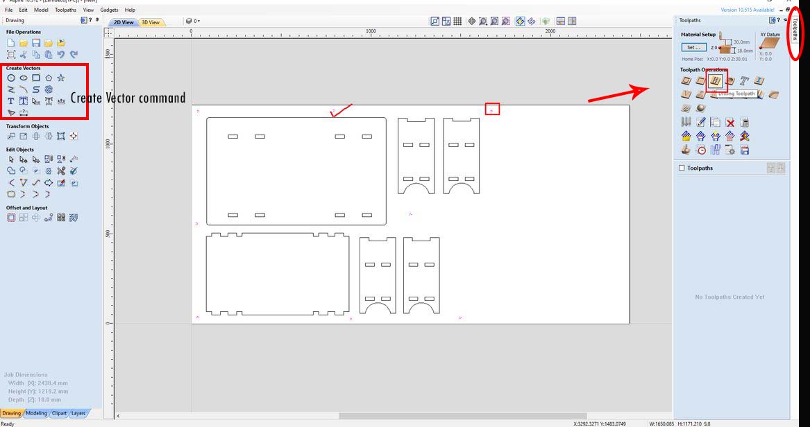
A file operations windows will pop up. Here, click on -->Import Vectors. and arrange your files in the material size we prepared.
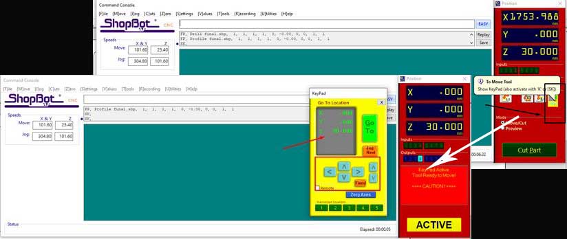
Meanwhile, I used the Shopbot Command Consle to set zeros for my machine. Click on To move pad highlighted, and then use the arrow points to navigate the machine drill beats. When its in the position you desire, ---> click on Zero axis and set up the axis. (After that donot alter the positions. Be careful when you set zero for Z-axis as you may destroy the end mill.)
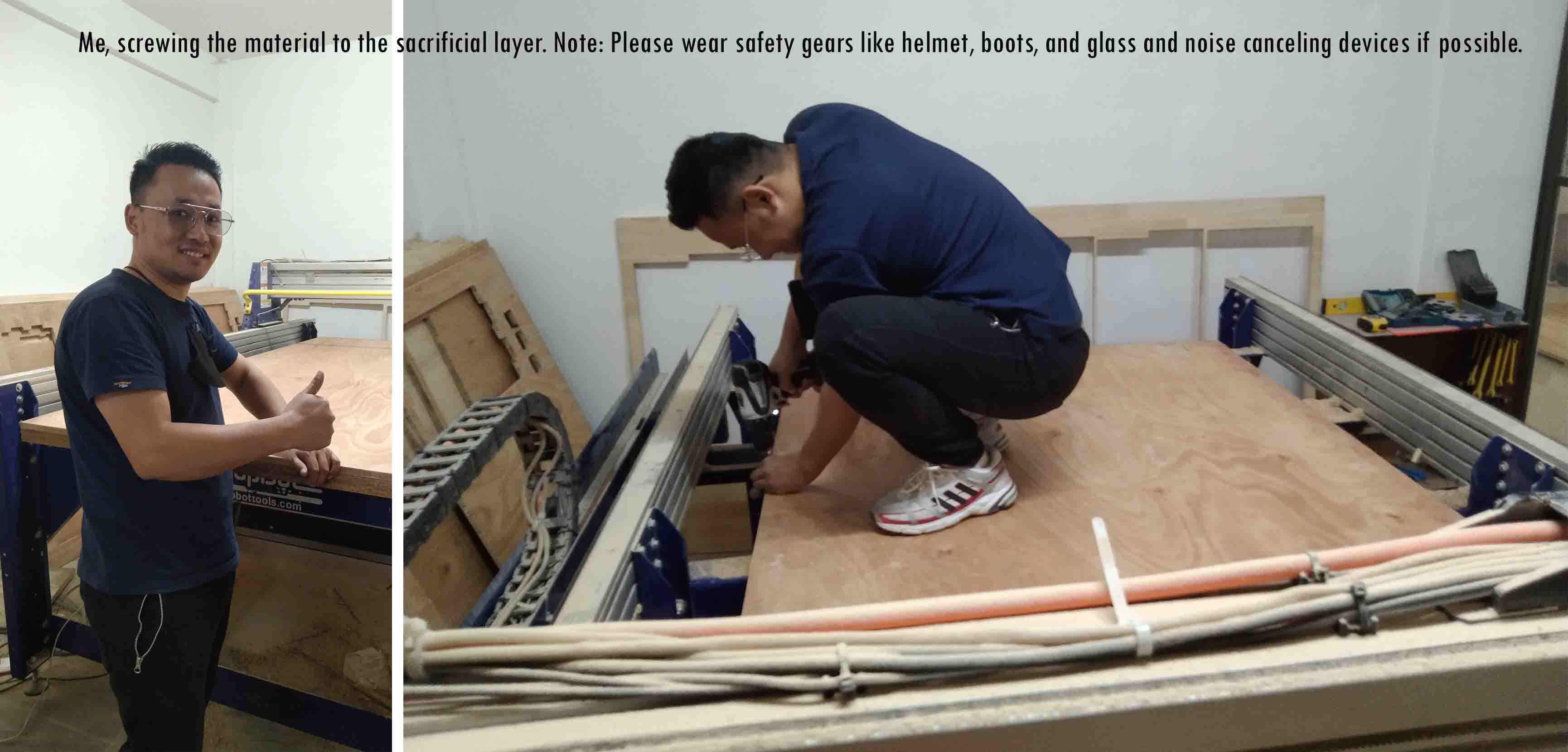
In order to fix the material so that it doesn't move positions while we cut the design, I fixed the material to the bed by drilling a hole and screwing it with the sacrificial board.
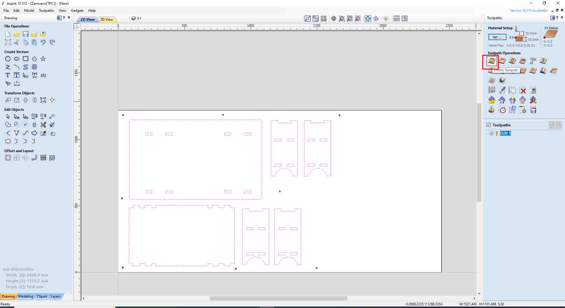
I created a hole using the Create Vector command. Then go to --->toolpath ---> Select tool path operation as "drilling toolpath". Please maintain drilling cut depth as 18mm as our material is 18mm.
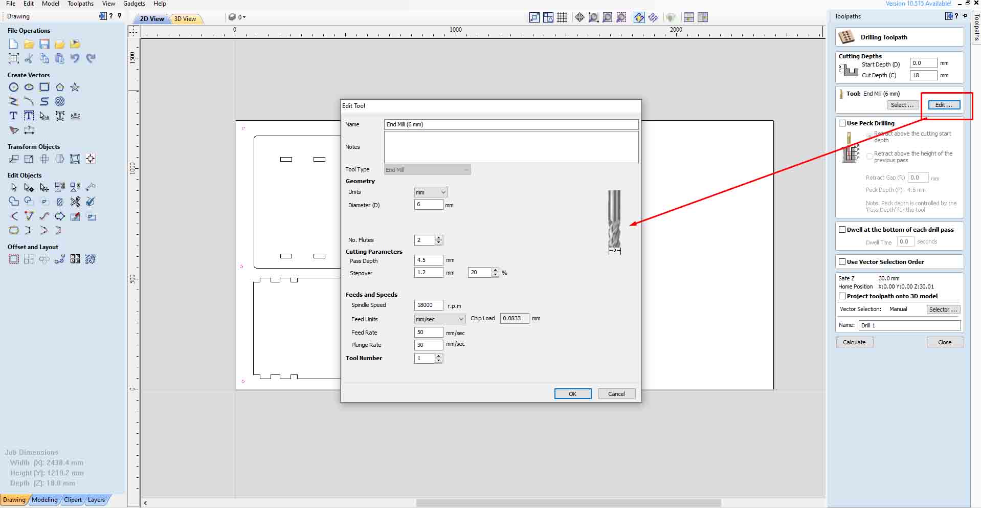
After that, you can select the tools but it is recommended that you edit the toolpath as shown below:
I hvae selected tool dia of 6mm, Therefore, following settings are done:
In Geometry:
Diameter =6mm and No. Flutes = 2 because my tool has 2 turns
In Cutting parameters
Pass depth = 4.5mm and step over = 1.2mm @ 20%.
In Feeds and Speed
Spindle speed = 18000 rpm, feed rate 50 mm/sec and plunge = 30 mm. Now my tool will plunge or drill 30mm in one round.
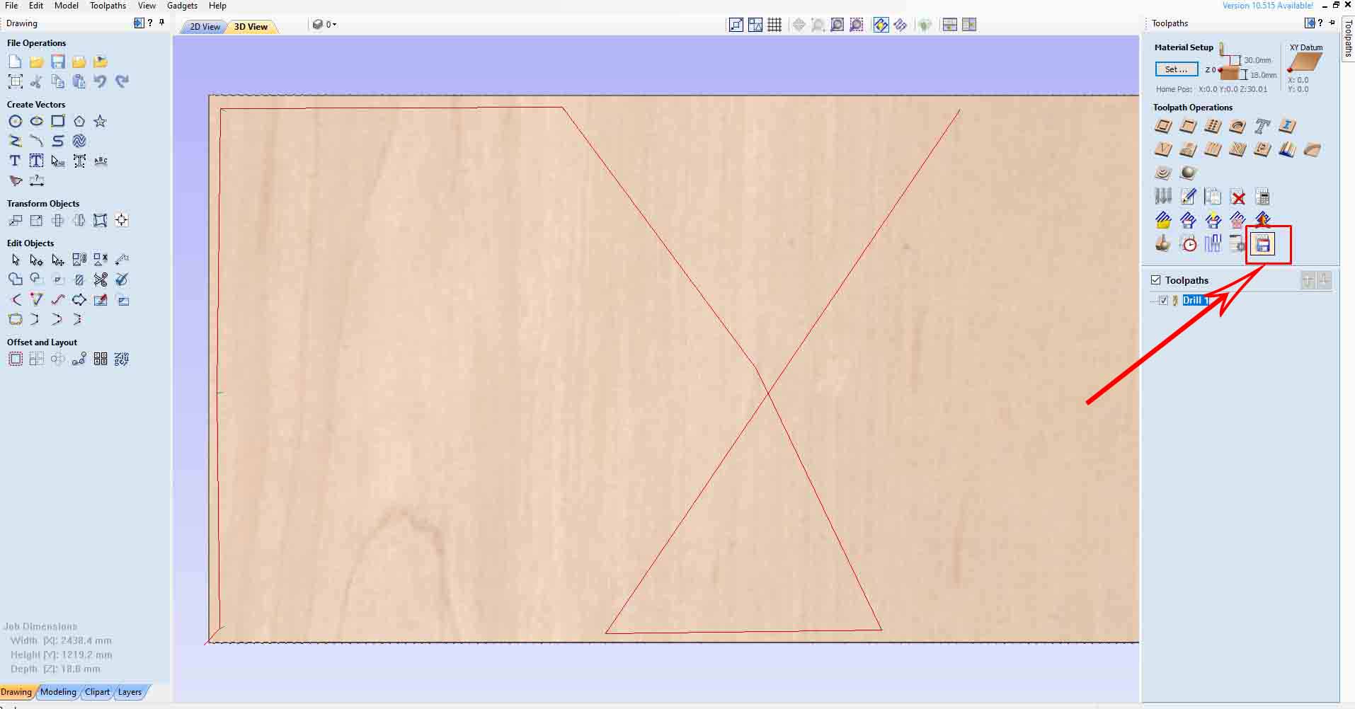
Then press calculate and close the window. Tick the toolpath we created, here drill1 and save the file in the desired location.
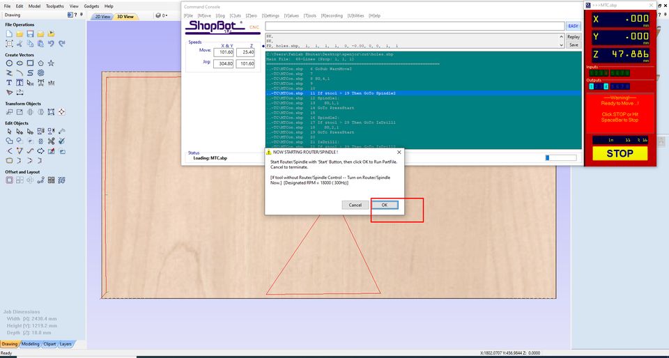
After that, we again go back to the shopbot consel and start the operations from there. First click on "Cut part" ---> choose the file and then click OK.
Note: my shopbot machine has some issues and they might have repared some parts, therefore, in order to spin the spindle ehad, We had to start remotely by pressing the green button.
After that, I screwed my board.
After that, I cut my furniture design. The machine is noisy. But no major issues were detected. Just like before, I created a toolpath for the machine and saved it. Then, I clicked on the Cut part command in shopbot console to cut the parts. Only, this time I used the "Profle" command ro create a path. Note: Do not change the home or zeros of the machine now. Check the setting and make changes if necessary. For me, I didn't make any changes.
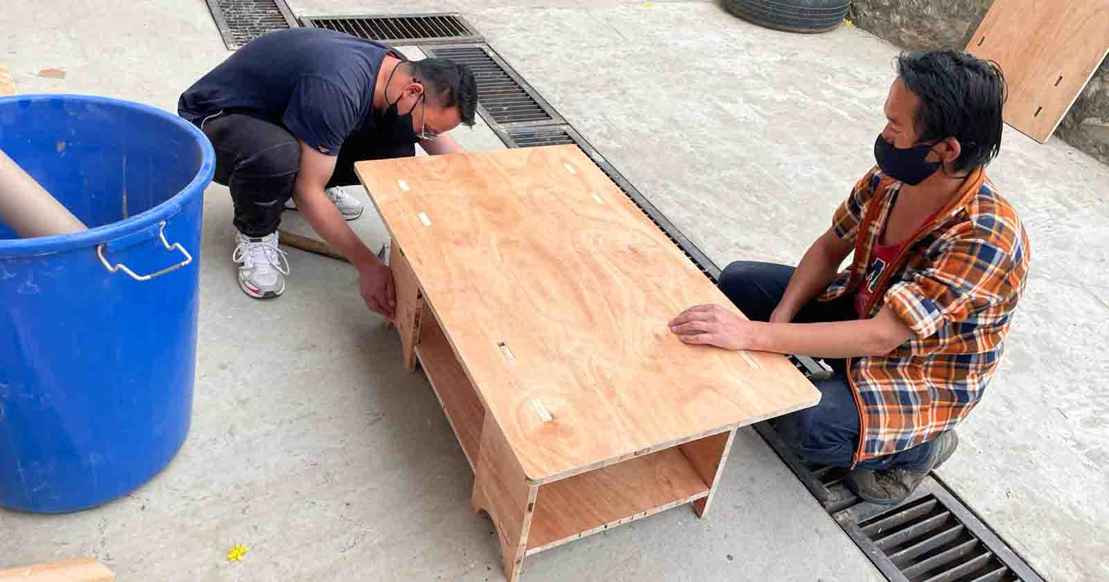
After my design are cut, I stopped the spindle and took out cut parts by first removing the screws. The cuts were press-fit and clean but material is not of a good quality.
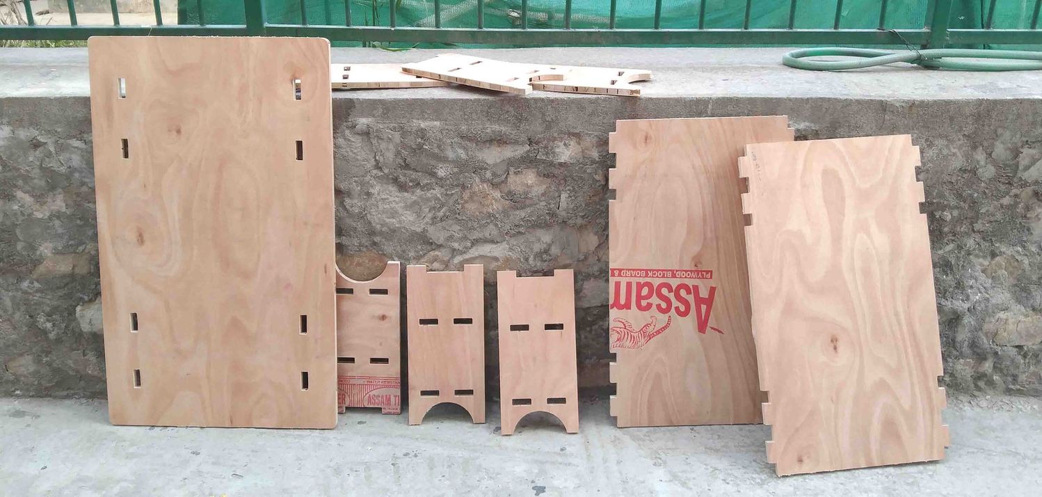
I tried to see how the press fit is working with Tashi, our lab technician. It fits well. In the cuts where we can not fit, we used some wood rubbing files to clear some paths.
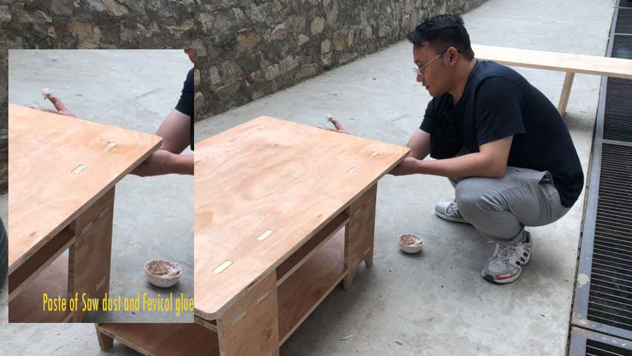
There were so many defects. In order to hide the defects, I prepared a saw dust paste by mixing Fevicola and saw dust.
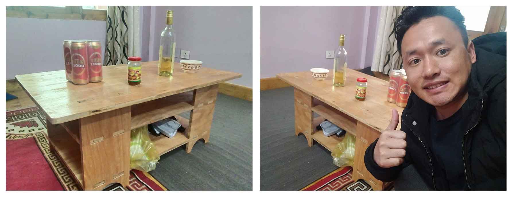
After that, I dismentled my furniture and painted it with glossy paint and I took it home and fixed it in my living room. Now, I am a happy man with my table which I made it for free for myself, instead of buying it from the market.
Watch my YouTube videos to know more about the process
Download my design file here. It is in .f3d format.