
Electronic Design
Group Assignment
Group Assignment:
- use the test equipment in your lab to observe the operation
of a microcontroller circuit board
The group work that our group has done can be seen here
Individual Assignment:
redraw an echo hello-world board
add (at least) a button and LED (with current-limiting resistor)
check the design rules, make it, and test that it can communicate
extra credit: simulate its operation
Introduction to Eagle
I attended the lecture on elctronic design by Prof. Neil on 2nd March, 2022. I reviwed some of the components dicussed by Professor in his lecture.
In order to get started with the electronic design, I was introduced to Eagle by my instructor. I downloaded the Eagle from here. However, Eagle is not an open source software. Prof. Neil stronly recommended the open source software such as KiCAD
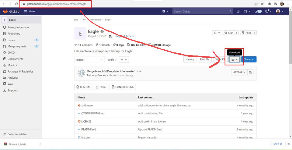
After installing the Eagle, I downloaded library from the fab container-fluid
and uploaded it to my library manager.
Go to the Eagle Library in FabCloud.
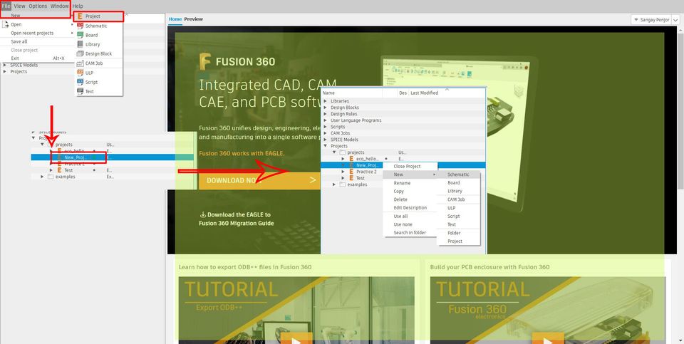
Open Eagle. Go to the "File" and create a New Project. In the project management folder shown at the right side, right click on the "New Project" and create a "New Sketch".
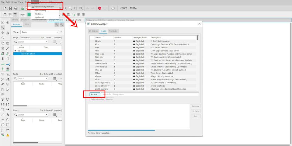
After that, before, sketching anything, go to "Library", click on "Library Manager" and I added the library that I have downloaded.
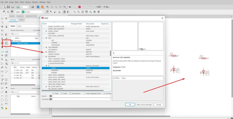
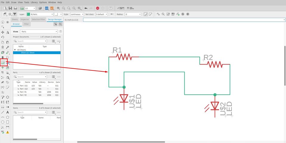
In order to add the components, click on the components ar as shown below and choose your components to add. As a practice, I imported 2 resistors and LED in my project. I used the fab library I added, earlier.
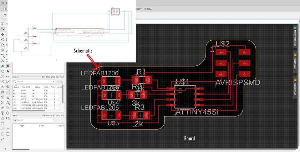
I made sketches using the "Net" tool as shown:
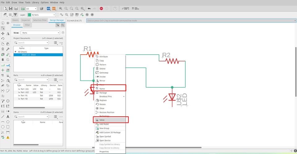
You can rename and add values to the components by right clicking on the components.
After netting and renaming the components, finally it's time to switch to the board by clicking on the symbol as shown below:
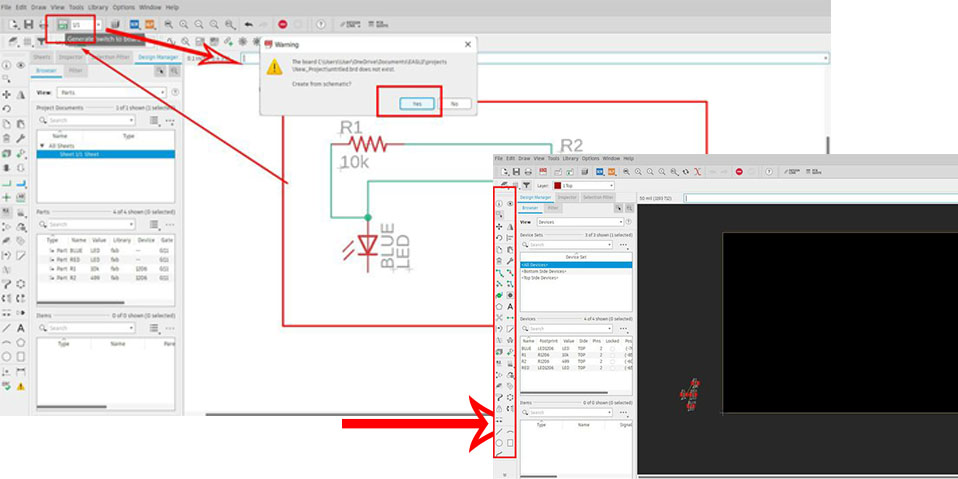
Click on Yes when prompted.
In this board, you can finally design and place your components according to your design. There are several options to Route.
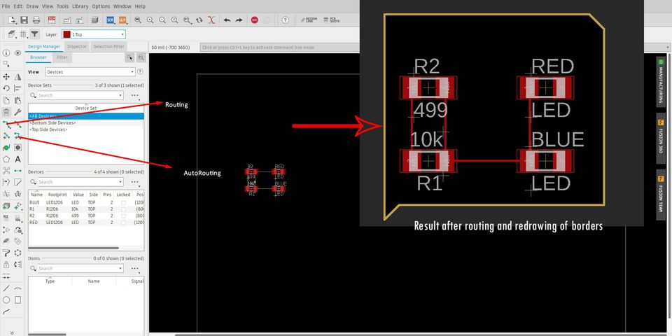
I also tried to get familiarised with components and routing with the help of some other shematic and board designs which makes no sense at all. (Just for learning).
Eco_Hello World Board
Several ioptions were available to redraw this board. However, in my lab's inventory, we have ATtiny44 micro-controllers available. Therefore, I chose to redraw this board.
It was suggested that we add at least a button and a LED to this board. Therefore, the
final components required are as follows:
1. ATtiny44 micro-controller
2. LED red
3. LED Green
4. 10k ohm resistors
5. XTAL 20MHz
6. ISP (2X3 pin header)
7. FTDI (1X6)
8. Tack Switch
9. 499 ohm resistors (2 numbers)
10. 1 microFarad capacitor.
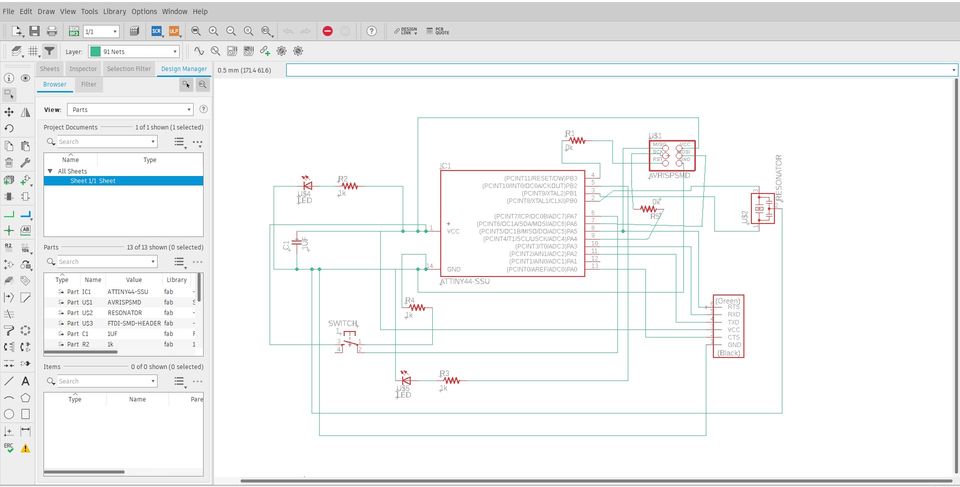
Schematic Design is done in Eagle. I used the components listed of fab library which I imported earlier. I added a button, a GREEN LED and Resistors of 100 ohm. Resistor is added in series with LED so as to limit the current flow of 5V from IC will overheat and damage the LED. To calculate the value of the resistor to be added to your LED, firstly, you need to check the data sheet of LED, for mine the GREEN LED. Data sheet
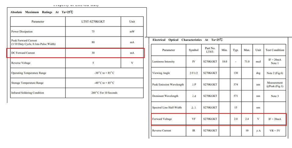
From the Data sheet, I got DC forward current as 30 mA and forward voltage
as 2V. Using Ohm's law I=V/R whereby I is current in Ampere, V is voltage
in volts R is a resistor in Ohms.
There R=V/I
Modifying the above formula, we can say that R=(IC Voltage-Forward Volatge)/DC forward Current.
R=((5-2)/30X10^(-3))
Therefore, R=100 ohm. Hence 100 ohm resistor is used with a GREEN LED.
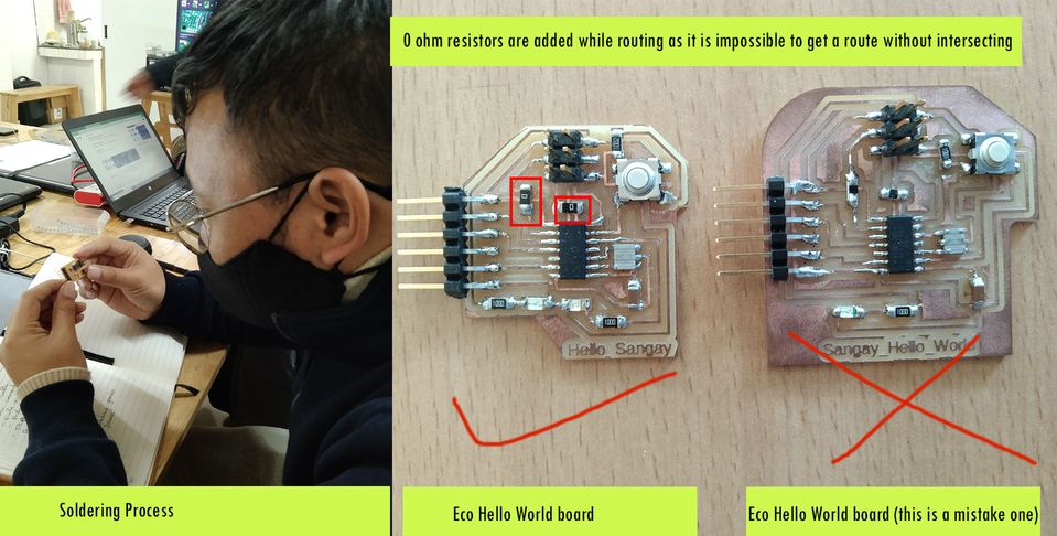
The board design is done as so as to create a minimal wastage of the lab inventory, especially the PCB board.
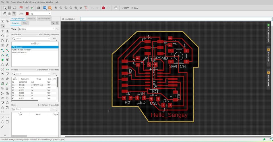
I also made a mistake in the first attempt to make the board. Due to so many intersections I have deleted the GREEN LED. Therefore, I have to print it again and soler the board.
The following video shows the summary of week 5 assignments
Testing of Eco_Hello World Board
I want to test my eco_hello world board to blink my LED.
Downloads
Download the files from here