
Electronics Production
My Workplan for the Week
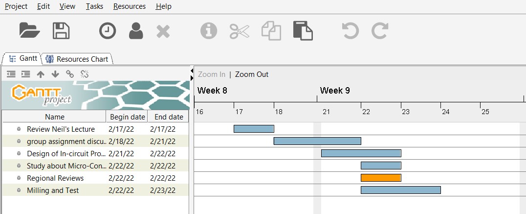
Group Assignment for Week 4
Group Assignment:
characterize the design rules for your in-house PCB production process
extra credit: send a PCB out to a board house
The group work that our group has done can be seen here
Individual Assignment:
1. make an in-circuit programmer that includes a microcontroller:
2. extra credit: customize the design
3. mill and stuff the PCB
4. test it to verify that it works
5. extra credit: try other PCB processes
1. Making an in-circuit Programmer
Owing to the availability of micro-controllers such as Attiny45 and ATtiny44, I decided to make my FabISP using Attiny45 microcontroller. I referred Brian to mill and solder my FabtinyISP.
The Fabrication Process
1. Downloaded the files of traces and Outlines design by Brian.
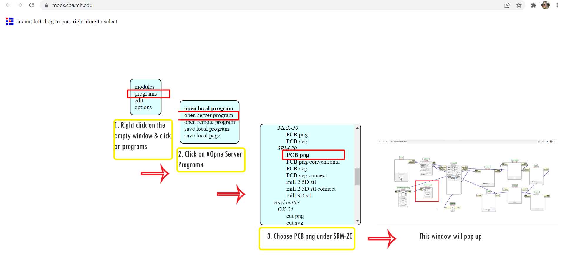
2. Prepared the rml files using mods community version here or the MIT mods version here. We used MIT mods version
3. Follow the following steps in the image:
 4. The windows above, delete the "WebSocket Device" as highlighted below and follow the steps to save the rml file.
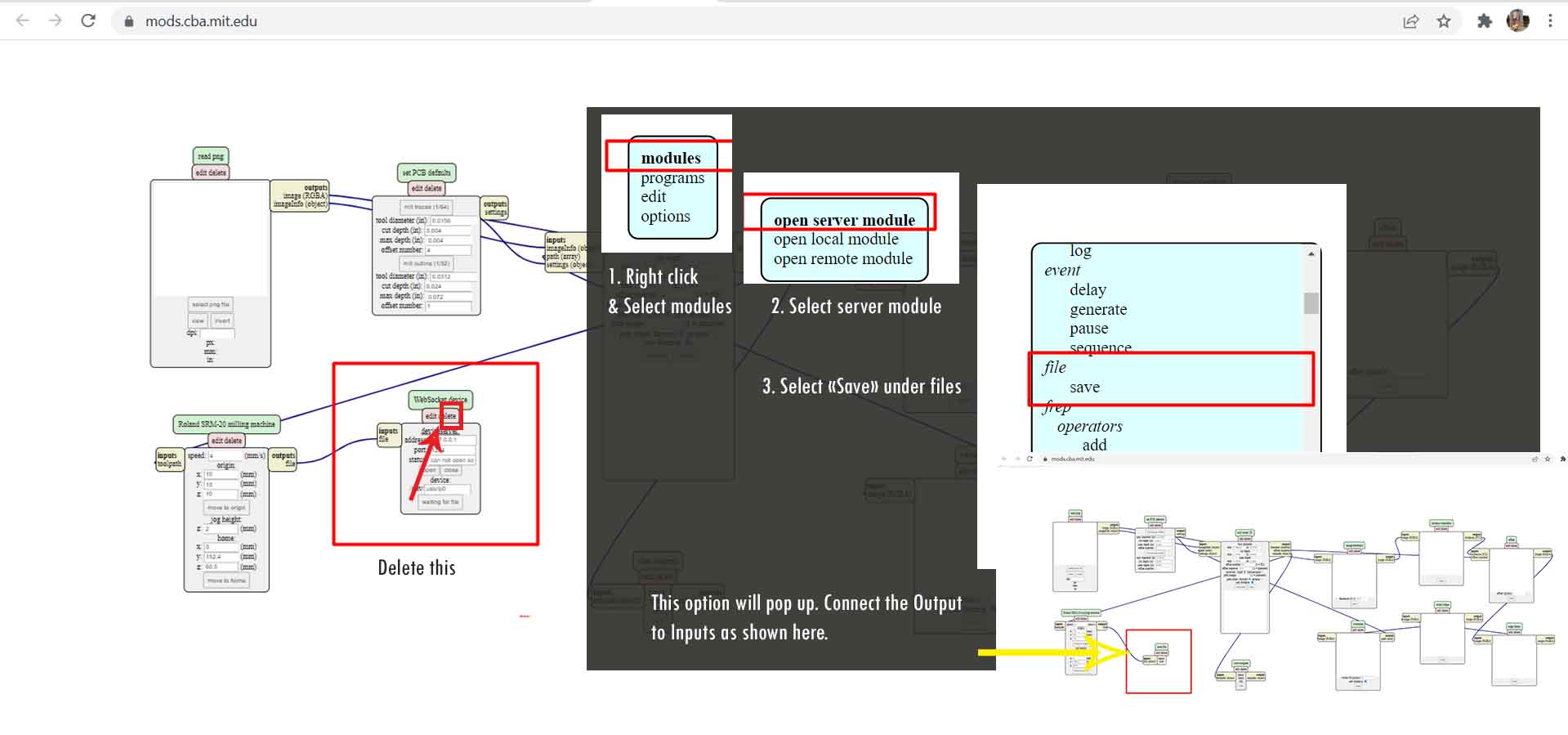 5. After that follow the following steps:
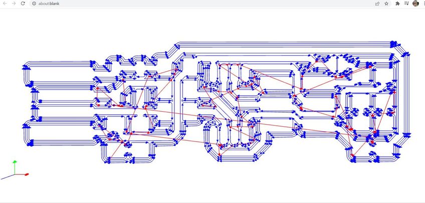
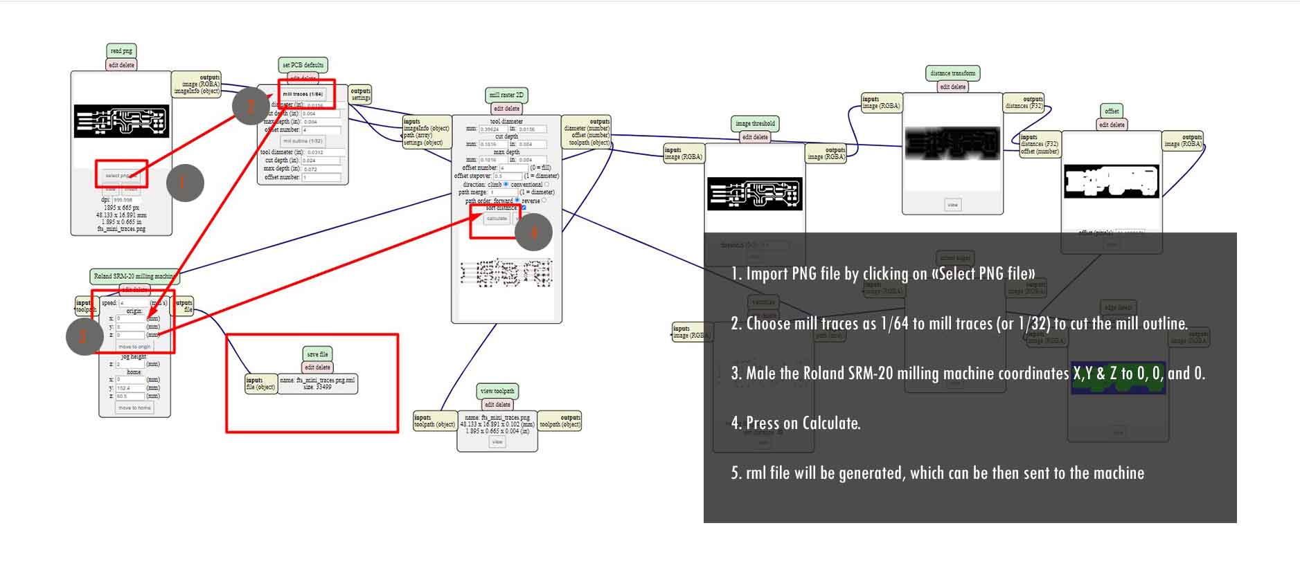 The following is the tool path generated for milling purpose.
 6. The rml file generated is then sent to "Vpanel for SRM-20", a software which is used to set zeros and print the PCB board.
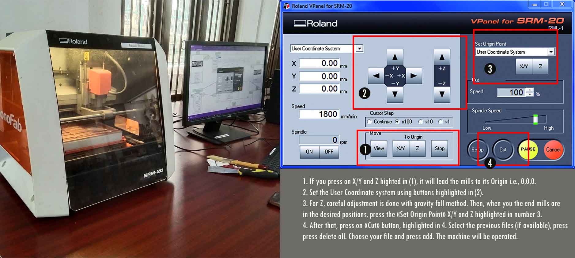
Procedures to fabricate using Vpanel for SRM-20.
1. Close the front door of the SRM-20
2. Press the power button "on" which is located on the top of SRM-20
3. Start the Vpanel from the desktop. Follow the steps in the following image.
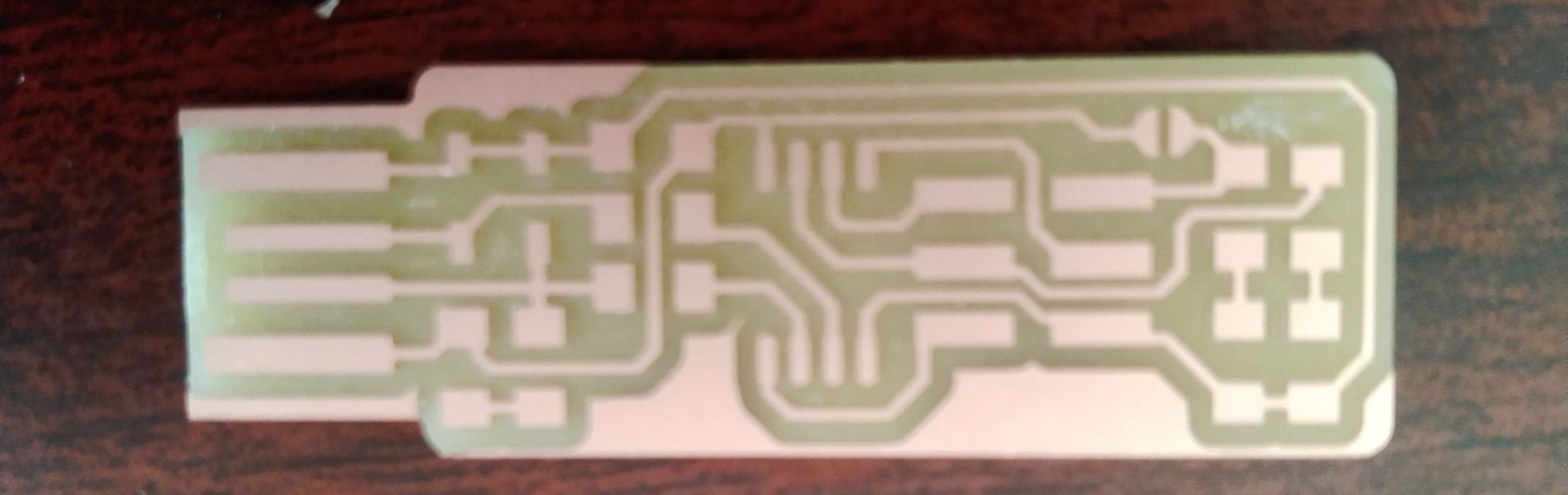
The fabricated board is as seen below:
The Soldering Process
Mr. Take, my fab instructor briefed us on basic soldering practices. Before soldering any components, making a list of components and
making it ready is important as shown below:
As shown to the right, the components required to solder are:
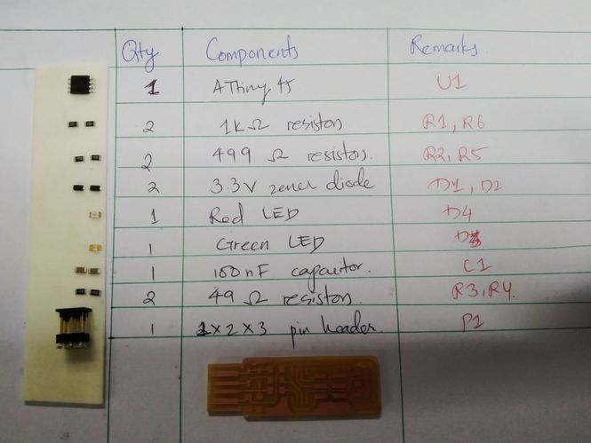 1x ATtiny45 or ATtiny85
2x 1kΩ resistors
2x 499Ω resistors
2x 49Ω resistors
2x 3.3v zener diodes
1x red LED
1x green LED
1x 100nF capacitor
1x 2x3 pin header
I started soldering. As per the instructions of Mr. Take, before soldering any components, I placed an paste of solders on one of the edges. Then I placed the
components and soldered it one by one. It was a tiring one.
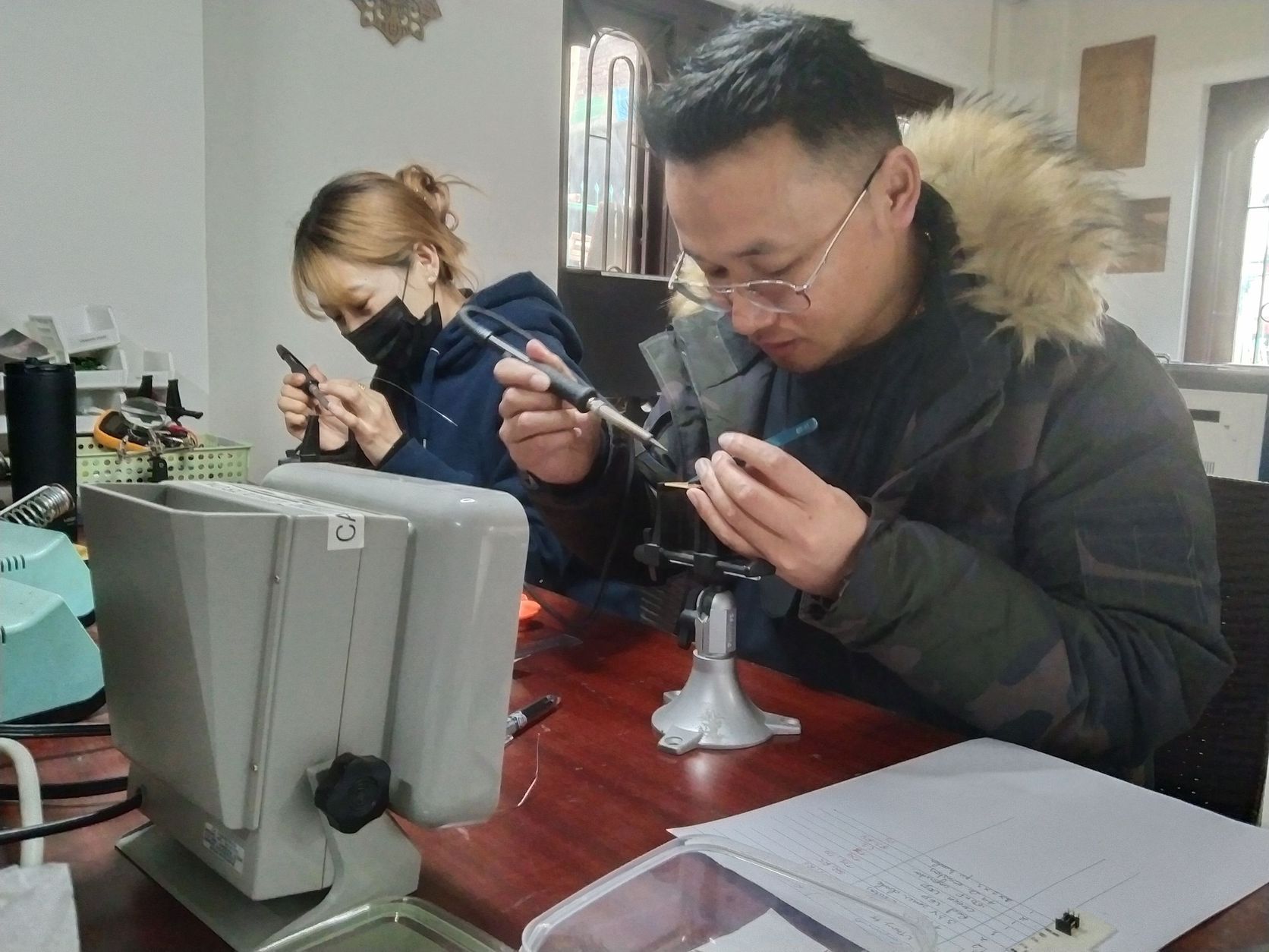
Picture below: Me soldering my fabISP with Sonam Deki
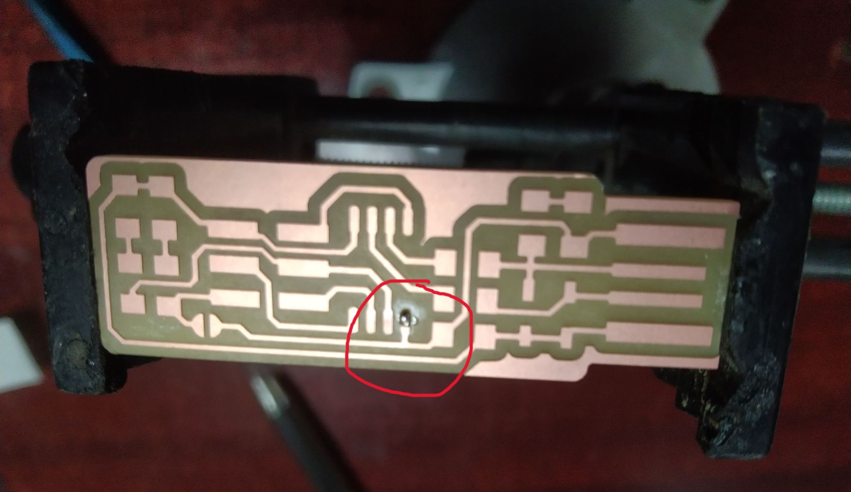
Aftering soldering, I tried to remove the extra coppers on my board to make it more clean, however, I accidentally removed a of my trace. As I was about to dump my board, feeling frsutrated, my instructor asked me to maintain it with copper wires available in the lab. Therefore, I did some make up with the wires and soldered it.
The soldered PCB after fixing is shown below:
2. Programming FabISP
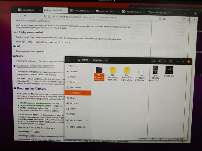
A detail of Programming the ISP is given by Brian. It was mentioned that programming the board fabISP is quite compliacted in windows, however, linux is highly recommended. Therefore, I used the PC in my lab which has a installed Linux to program my board.
Following steps are followed:
1. Download the firmware source code and extract the
zip file.
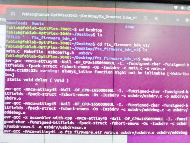
2. Open terminal and run cd to view the directories.
3. Run make. A file called fts_firmware.hex. is generated.
4. I opened a makefile in text editor Notepad and changed the the that says:
PROGRAMMER ?= usbtiny
to:
PROGRAMMER ?= atmelice_isp
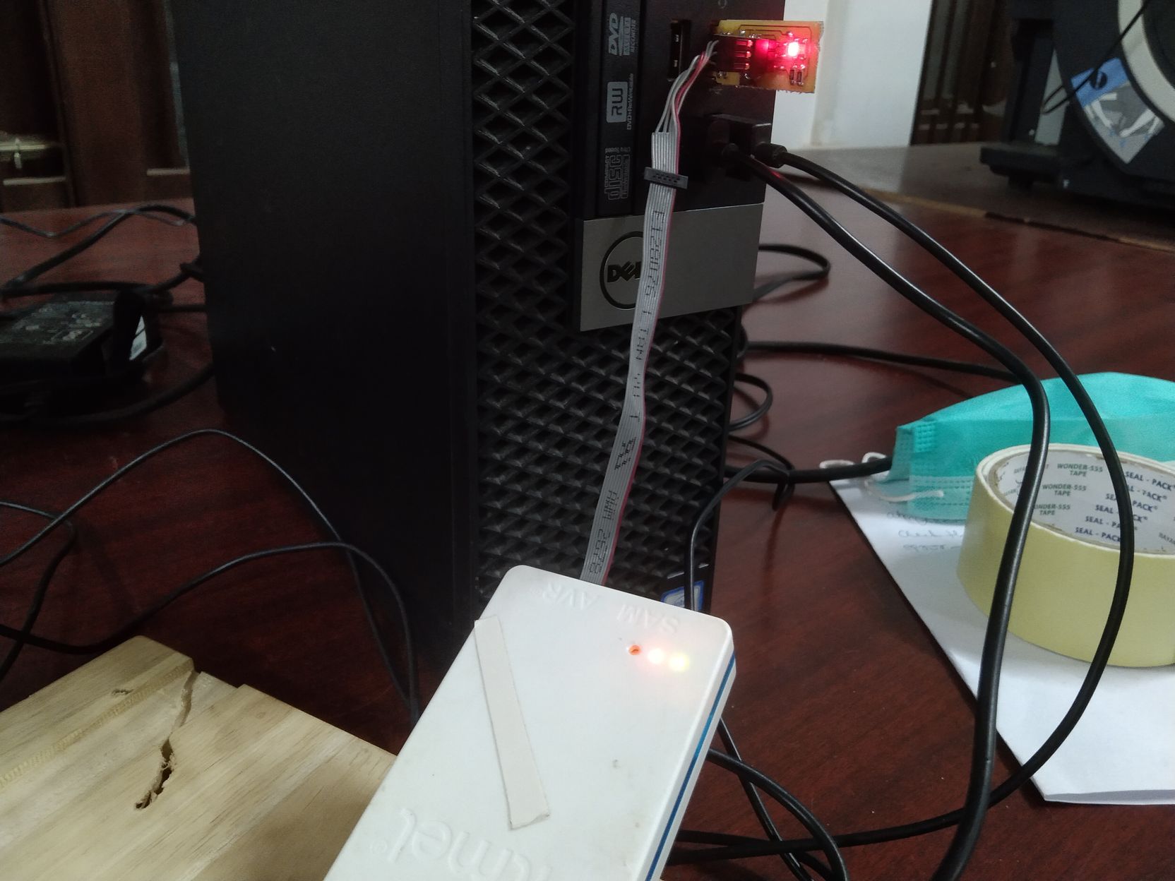
5. I plugged the board into a USB port. A red light was glowing. It means my circuits are correct.
6. I connected the programmer to my board through ISP header.
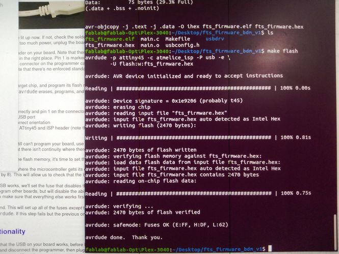
 7. Run make flash. It was successful. No errors were detected.
 8. If there are no erros, Run make fuses command. This will set up all of the fuses except the one that disables the reset pin.
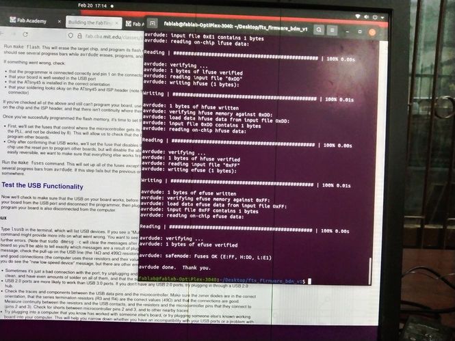 9. After that it was recommended that we check the USB functionality before blowing up the fuse that will enable it as a programmer. Therefore,
I unplugged my board and programmer.
9. After that it was recommended that we check the USB functionality before blowing up the fuse that will enable it as a programmer. Therefore,
I unplugged my board and programmer.
10. I plugged back my ISP and ran lsusb command in the terminal. "Multiple Vendors USBtiny" is displayed. My programmer is finally ready.
11. Finally, I blew up the fuses and my programmer is ready! Hurray!!!
The details of processes can be viewed in the following video.
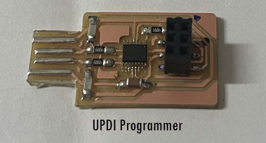
UPDI FT230XS Programmmer
After the return of our Guru Suhas, I wanted to try out new boards and new programmers. Therefore, he instructed me to explore UDPI programmer which requires only 3 pins to program. Therefore, I made programmer using Programmer UPDI FT230XS. I referred Programmer UPDI FT230XS in the git repository. The main advantage of using this programmer is that it need not be programmed to program other boards unlike fabISP we made and it requires only 3 pins i.e., VCC, GND and UPDI. I milled the board using MIT mods and SRM-20 milling machine.
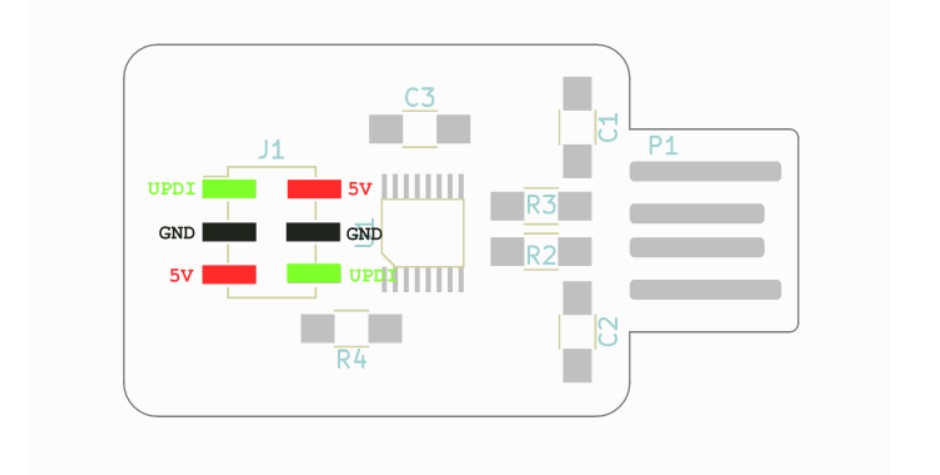
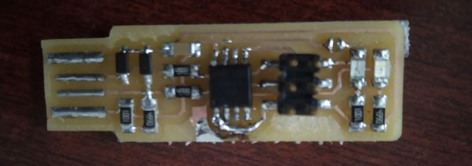
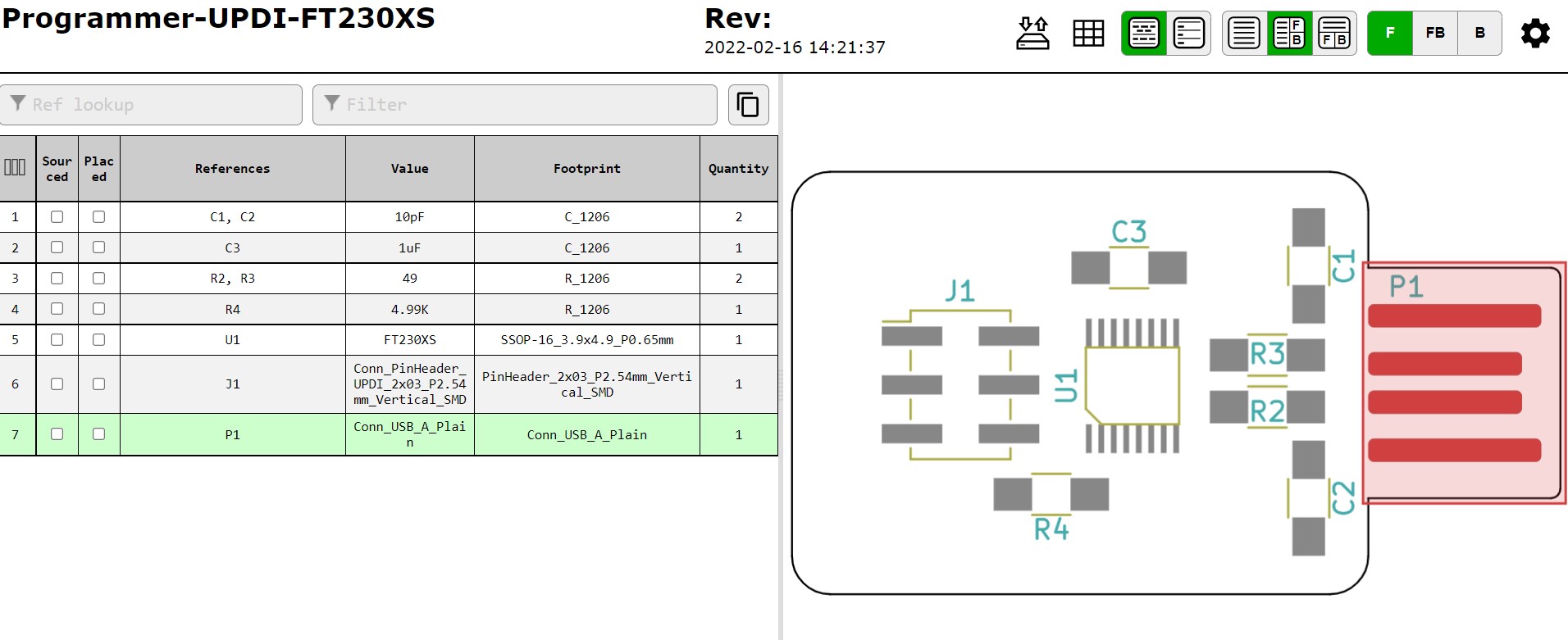
Download fabrication files from here. While soldering, the component details can be seen here. The details of the components is also shown below:
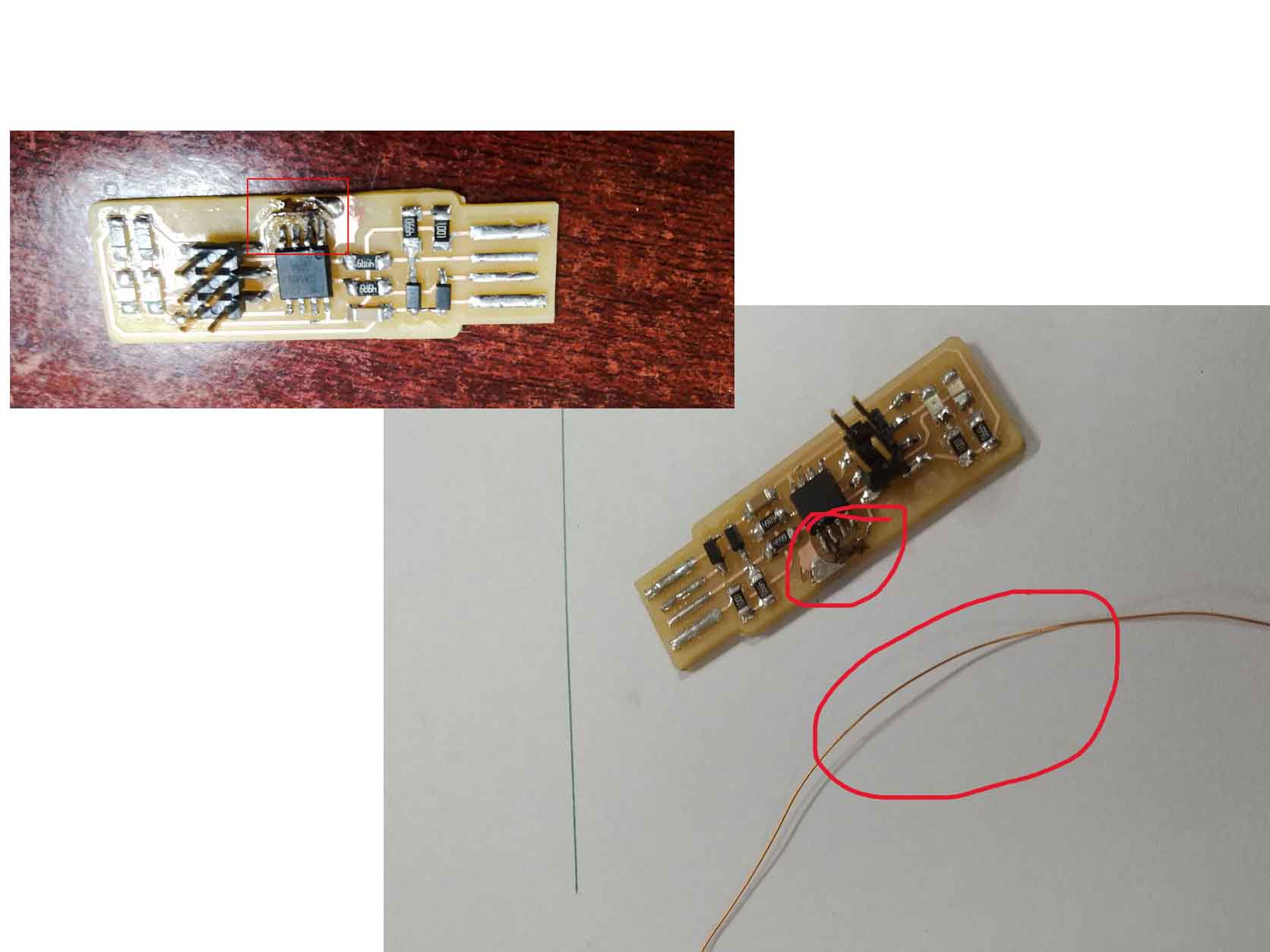
The soldered UPDI Programmer can be seen below:
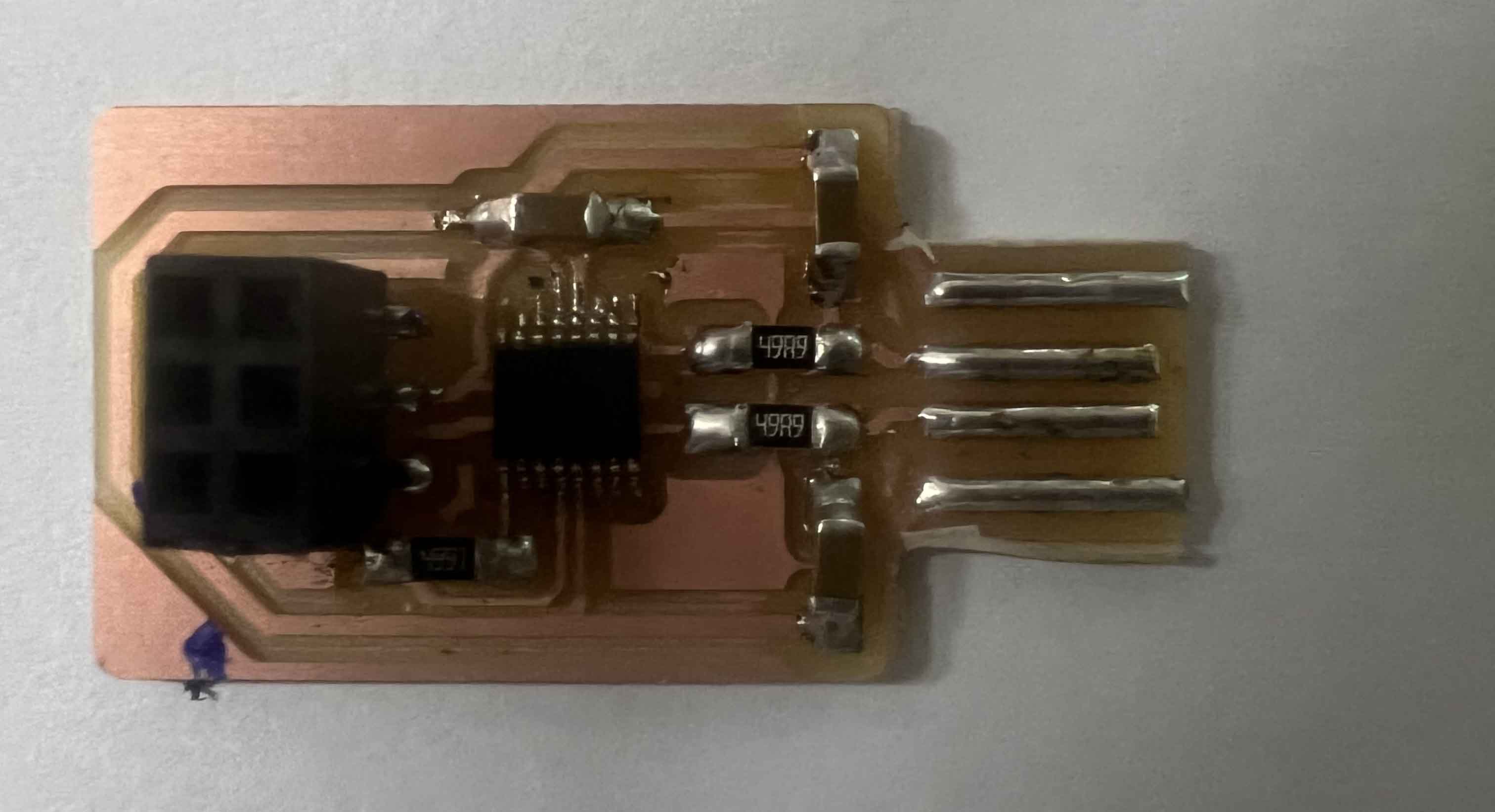
When I insert the programmer into my PC, my PC was not able to read it. I checked again and found out that I have soldered 10 uF capacitors instead of 10pF capacitors in place of C1 and C2. Therefore, I removed it and resoldered the components. Now my programmer is ready to be used.
To use UPDI Progammer, we need to install drivers. I downloaded the drivers from
d2xx-drivers for windows 64.
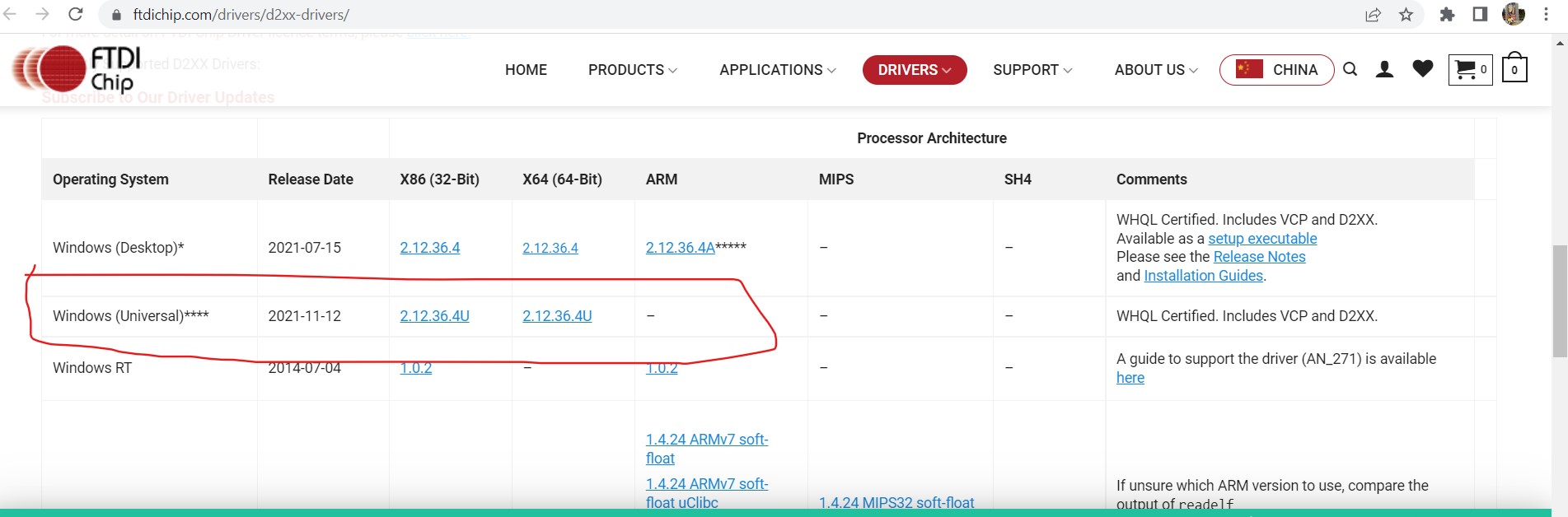
Download the files required. I downloaded 2.12.364u as I have windows 64bit OS. Use the following steps to isntall:
1. Extract the files.
2. Go to Device Manager and checkUniversal Serial Bus controllers. A new unknown device will be shown.
3. Right-click on it and update the drivers.
4. Choose your file locations and update.
Now You device will be readable and will be shown as USB Serial Convertor