
Computer Controlled Cutting
Group Assignment
You an see the group assignment here here
Understanding Parametic Design
With the use of Fusion360, I am trying to understand how parametric design works. In my earlier assignment, I designed a
computer fan with the parametric modeling. Parametric design means giving user defined parameters to the models. This helps us to modify the models
without actually changing it but just by changing the parameter dimensions.
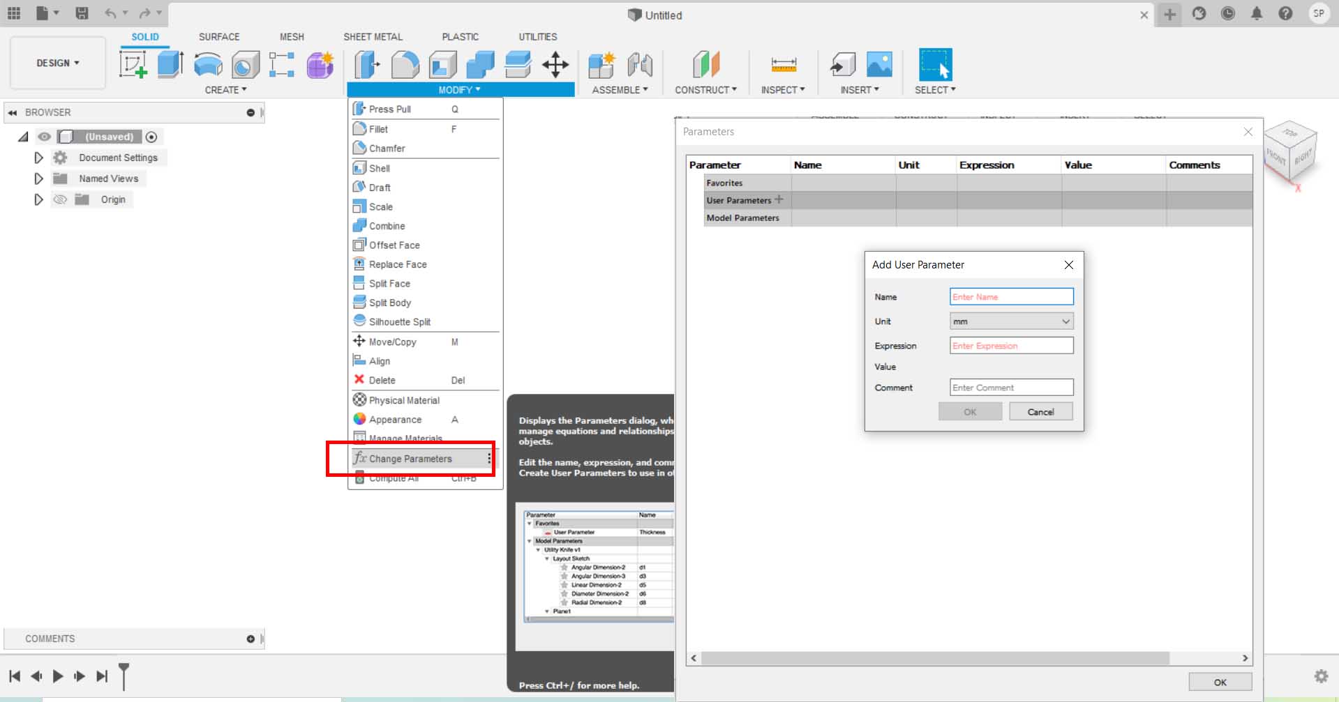
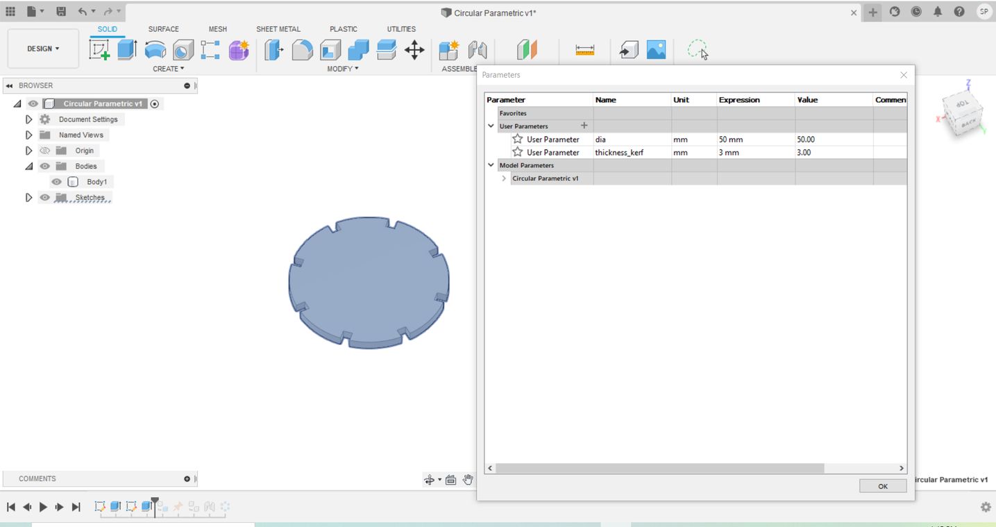
Parametic Design
I designed a circular disk with my own defined parameters. I just needed 2 parameters to design it ash shown below.
The after trying out the patterns, I can create a shape like this.The origial file can be viewed here
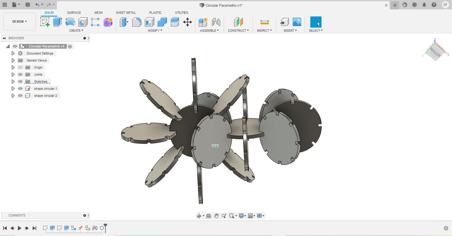
I also tried with some other shapes as well
View the files below:
Download the source file here
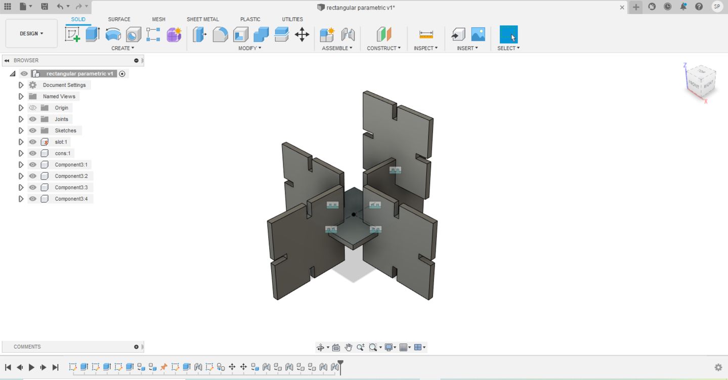
I like to make something cool. May be your definition of cool and mine could be different. I mean I would like to try to make something organic press-fit construction kit. To do that, I did refer the pictures from from this website.
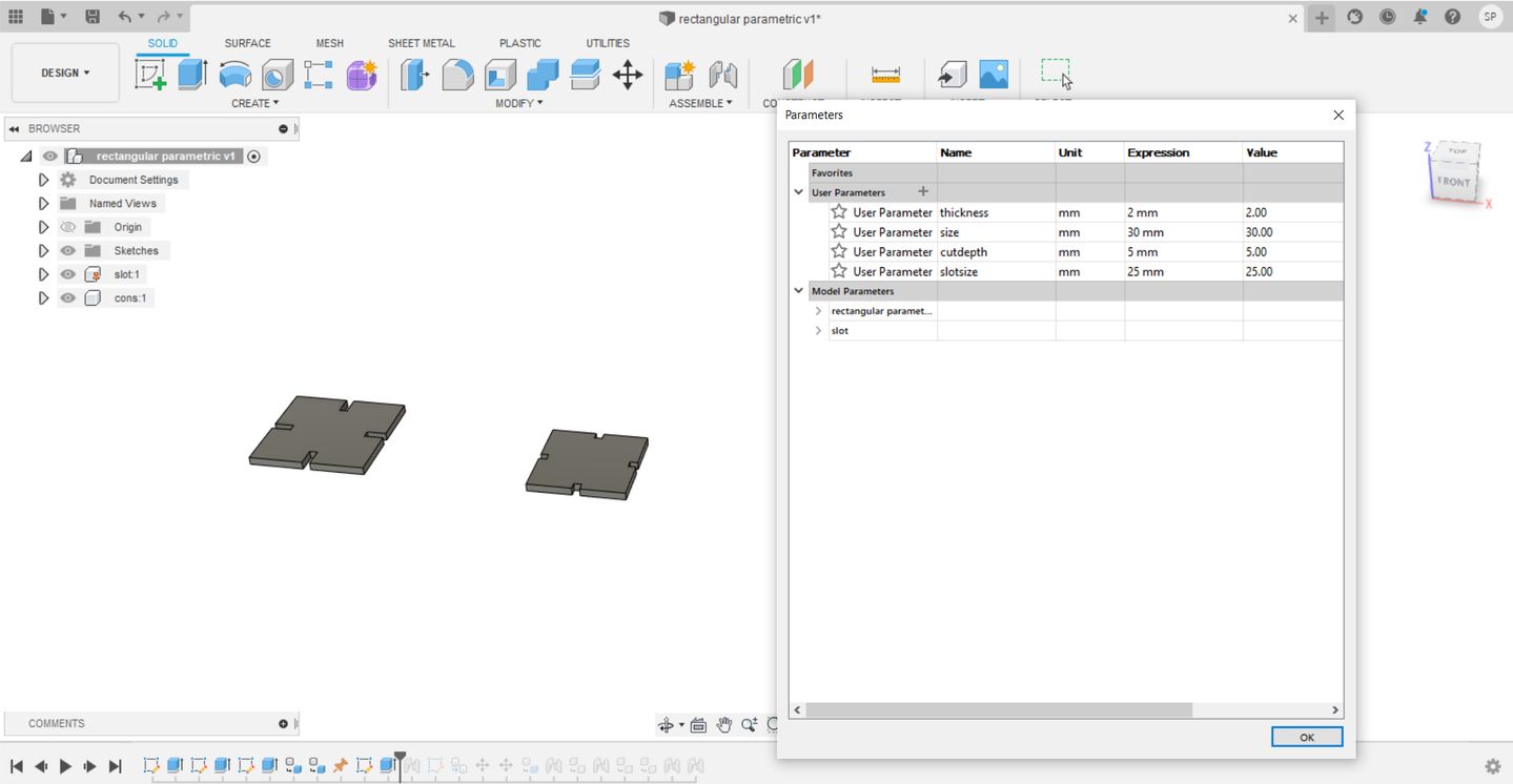
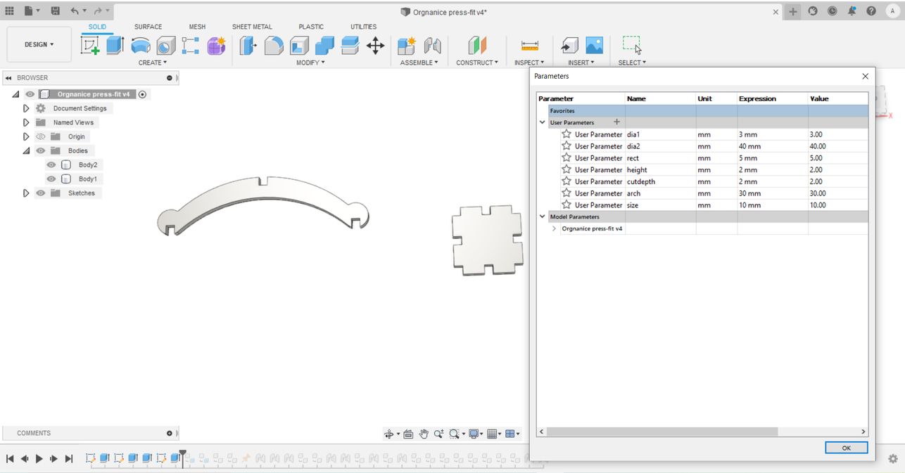
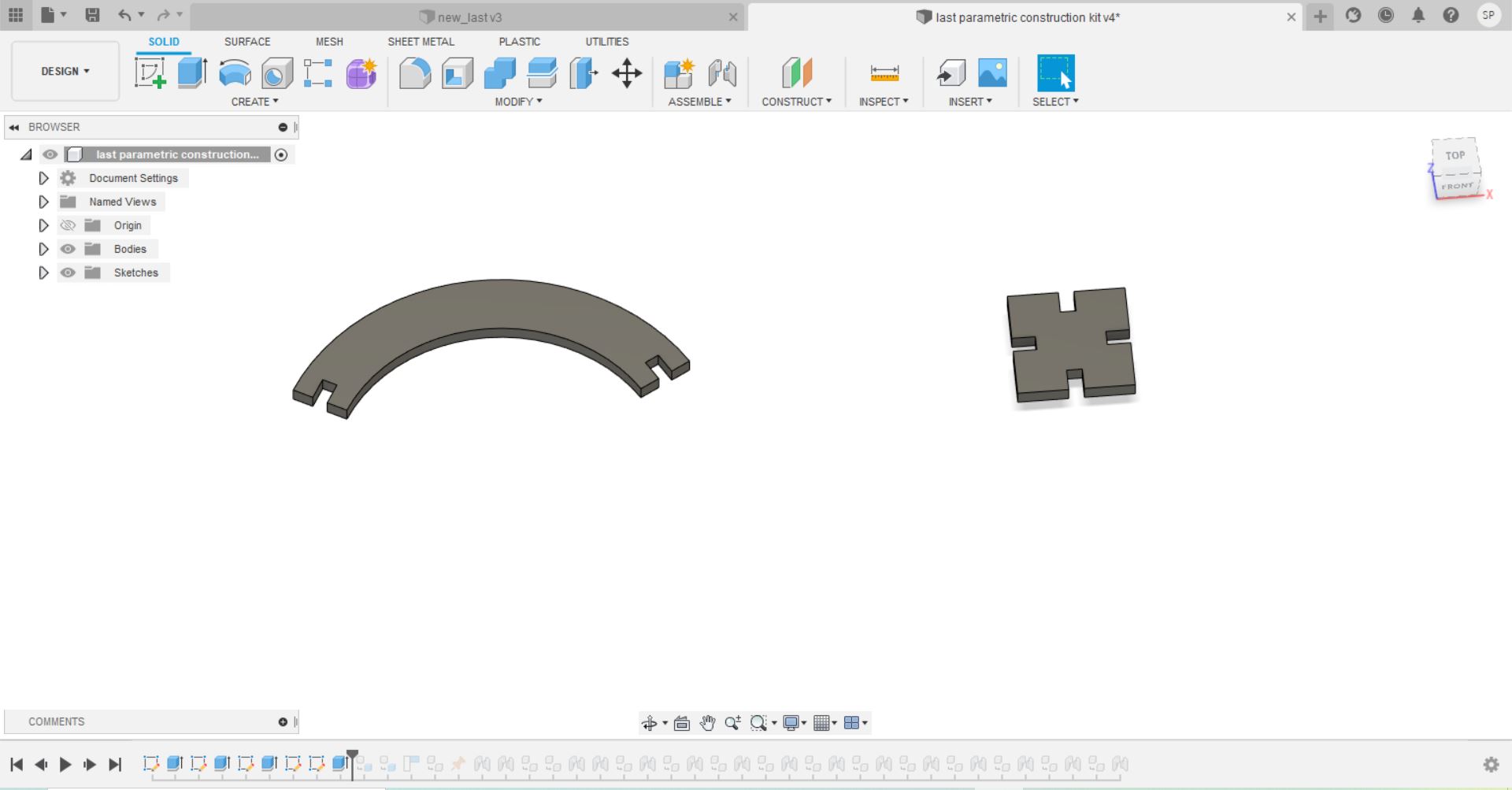
I designed a combination of curves as and a binder as shown below:
I want to try making multiple construction techniques as shown below:
Download the source file here
Laser Cutting
In order to cut my shapes in lasser cutter, I need check the thickness of my cardboard. It was 4mm thick. So, I changed my height parameters (my
intended cut depth) to 4mm. After that I created a .dxf as shown:
 1. Trace back the history to where you have created the shapes.
2. Then, CREATE SKETCH.
3. Click on "Create" drop down. Choose "Project/Include". Then choose "Project".
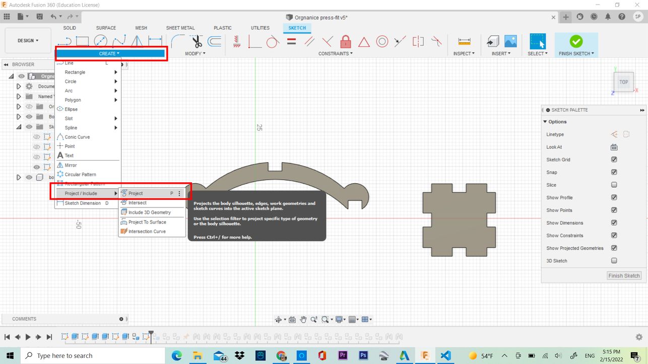 4. Choose the profiles and Click on "Finish Sketch".
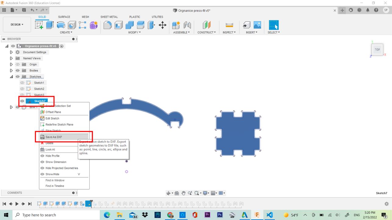
5. New sketch will be created with a red lock synbol. Hide the bodies and Components. Right Click on it and choose "Save as DXF"
.
 After reaching home from lab, I reflected back and I really didn't like design. I have also undermined the thickness of the cardboard which and when I
change the parameters, the curvature is not rally good. Therefore, I changed my model for my laser cutting activity.
After reaching home from lab, I reflected back and I really didn't like design. I have also undermined the thickness of the cardboard which and when I
change the parameters, the curvature is not rally good. Therefore, I changed my model for my laser cutting activity.
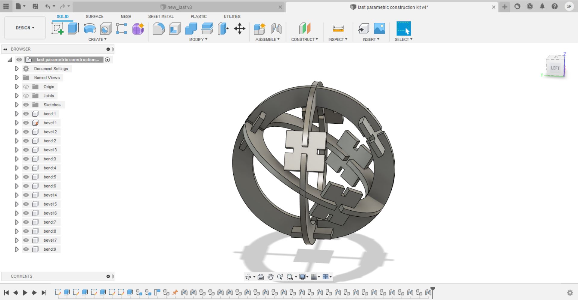
I tried to analyze the fits by joints comments. I am utterly disappointed that it doesnot work out the way I imagined. The fits intersect in
undesired places. I failed once again as shown below:
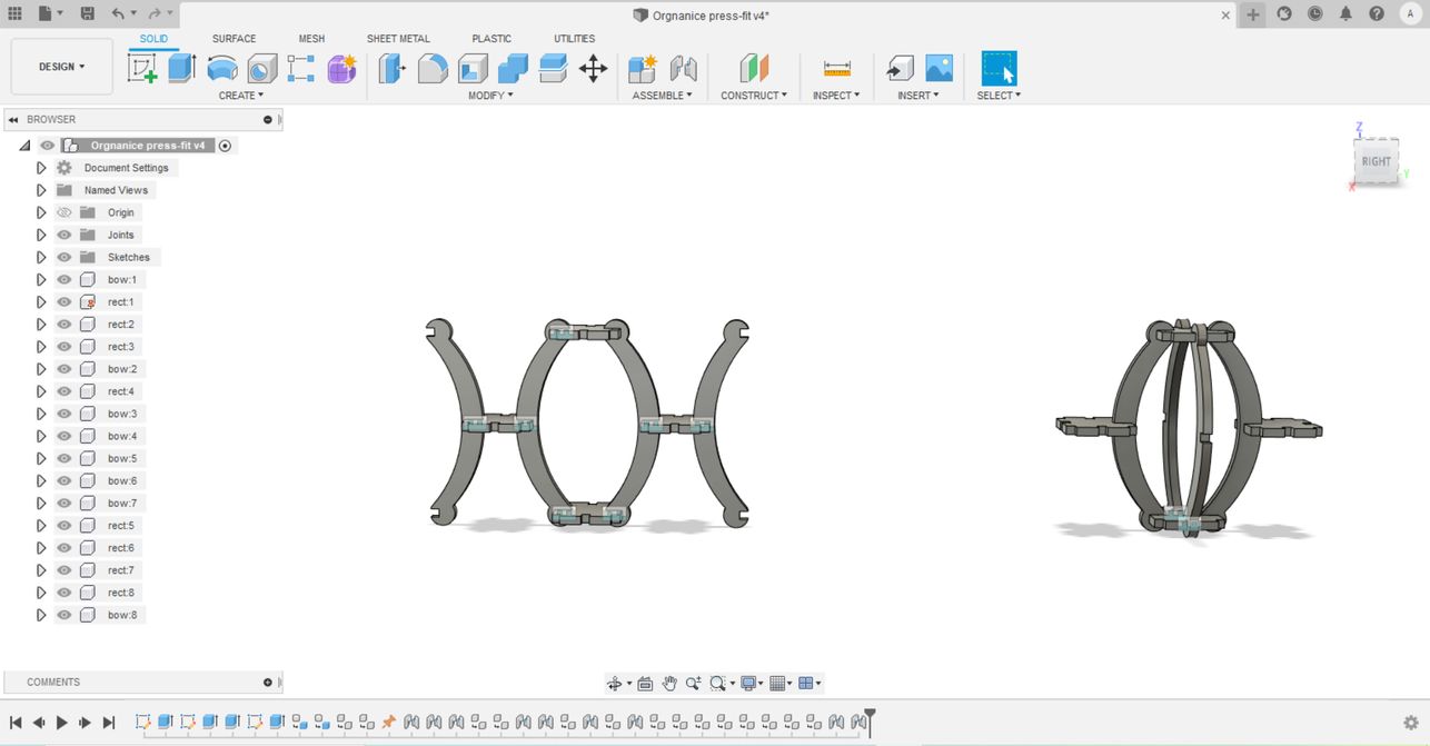
Therefore, I tried once again to model it as shown below. This time, I used the concept of circle with the help of a construction lines. I made Therefore
basics shape to design the kits this time.
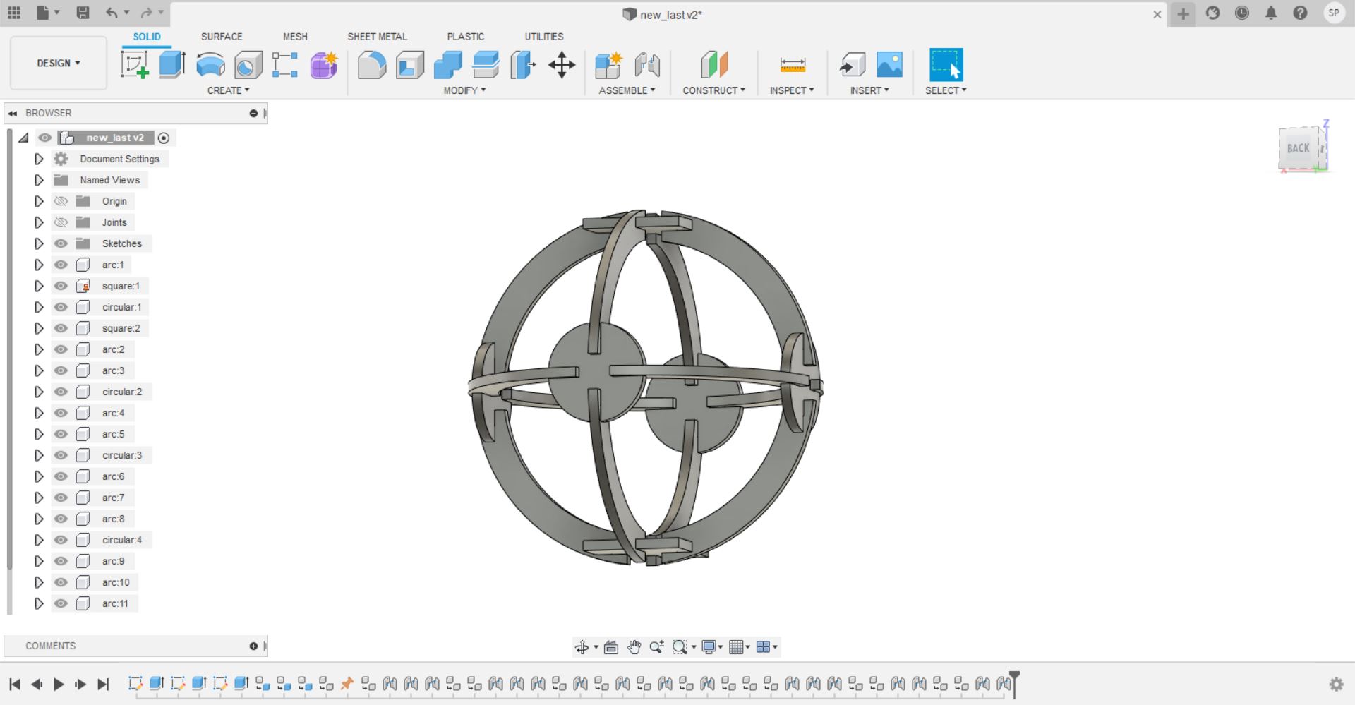
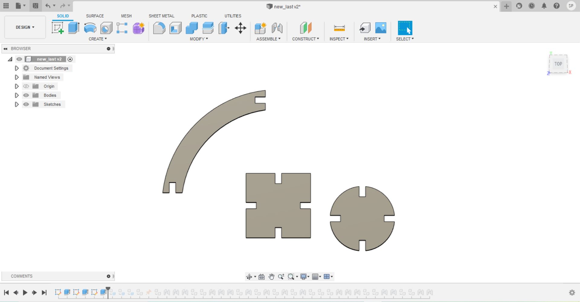 It comes out something like that when I try to analyze using the joints command. The most important parameter I considered is the thickness of
of the cardboard which was 5mm wen I measured it.
It comes out something like that when I try to analyze using the joints command. The most important parameter I considered is the thickness of
of the cardboard which was 5mm wen I measured it.
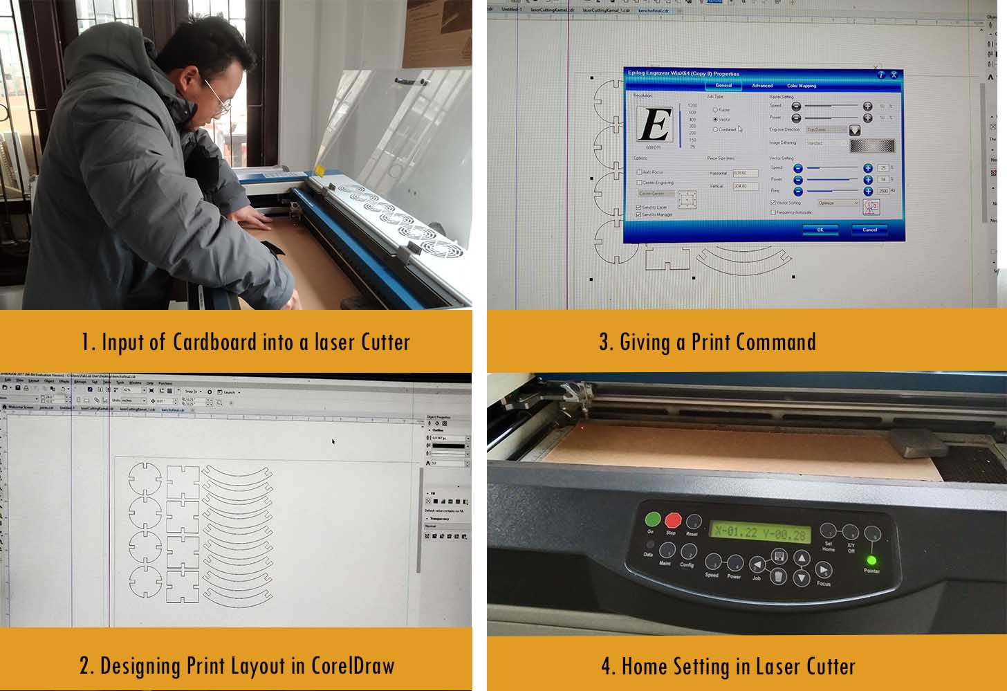
I proceeded to use the lasser cutting machine. I our node, as mentioned in the group assignment, we have Epilog Laser.
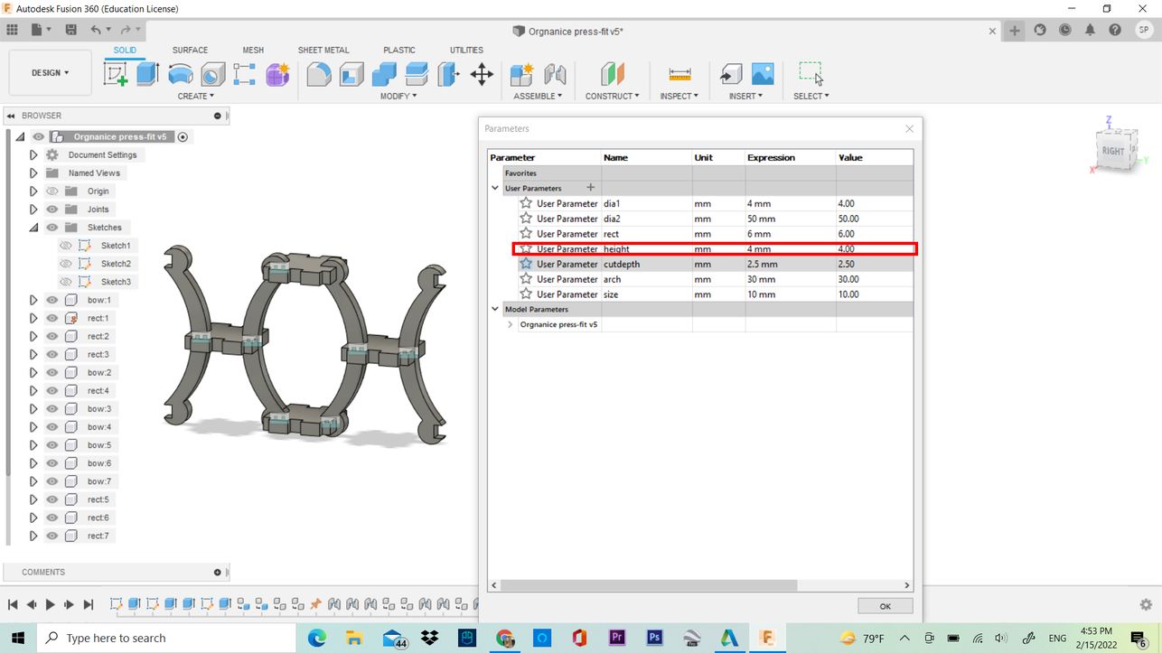
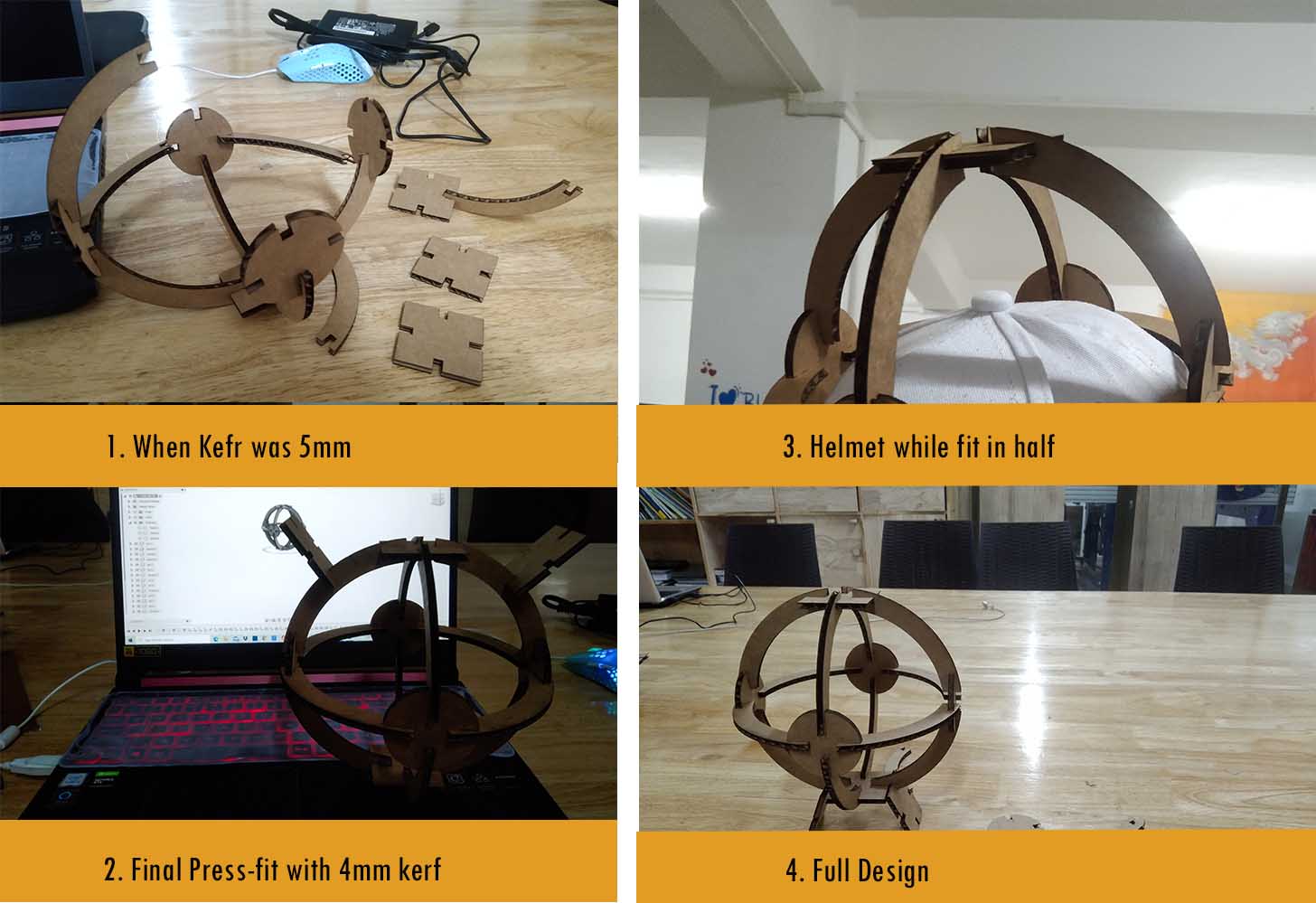
I was once again disappointed as I made a mistake in measuring the thickness as 5mm. It was actually 4mm when I measured again. Therefore, I
cut again and the results are good this time with 4mm thickness.
You can also download my model here
Note on Lasser Cutter Setting:
1. After the machine is put on, remember to put the exhaust fan on.
2. Before giving the PRINT command from the computer, place the material inside the workspace. (Check the nozzles)
3. Press "X/Y Off" button to set a new home/origin.
4. Adjust the nozzle and focus the beam on the desired location and press s"Set Home, then press "Go".
5. Give "PRINT" command.
6. Press "Go" on the machine.
Caution: Check on fire casualties.
Speed and Power Setting
From the group assignments, we determined the suitable power and speed to effeciently cut the board.
The following image shows my result.
Vinyl Cutter
According to Wikipedia, "A vinyl cutter is an entry level machine for making signs." It can print the computer designed Vector Files of
Patterns and Letters. Vector files can be produced by Inkscape which I have practiced in the second week of my fabacademy.
I designed the following patterns in Inkscape. First, I downloaded a cats outline image from
pinterest.
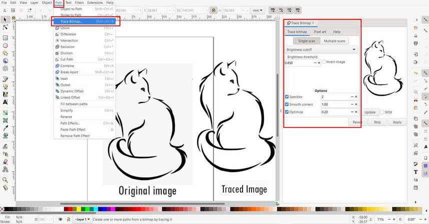
After that, I imported the image into my file, resized it and then I traced the image as trace bitmpa. Following steps can be followed:
1. Select the imported image
2. Go to PATH menu.
3. Click on TRACE BITMAP or press Ctrl+Alt+B.
4. Check settings and apply.
My final vinyl cutter printing is intended as below:
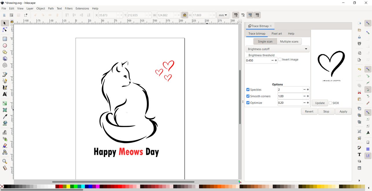
Download the Inskcape file here
I used my design to print using Vinyl cutter. The files must be saved in .svg format. The software that is used to give command to
Vinyl Cutter is EasyCut Studio. The following image shows my work.
Vinyl Cutter Settings.
My lab has a Roland CAMM-1 GS-24 Vinyl Cutter. You can find details about the product here Roland. You can also read the manual here.
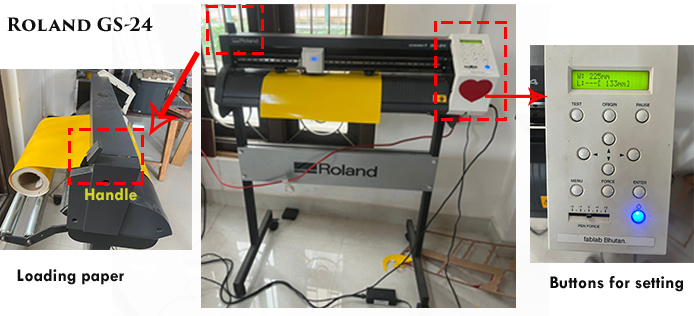
In order to cut the design in Vinyl Cutter, use the following settings.
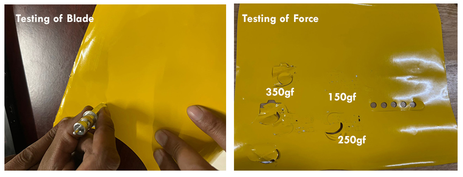
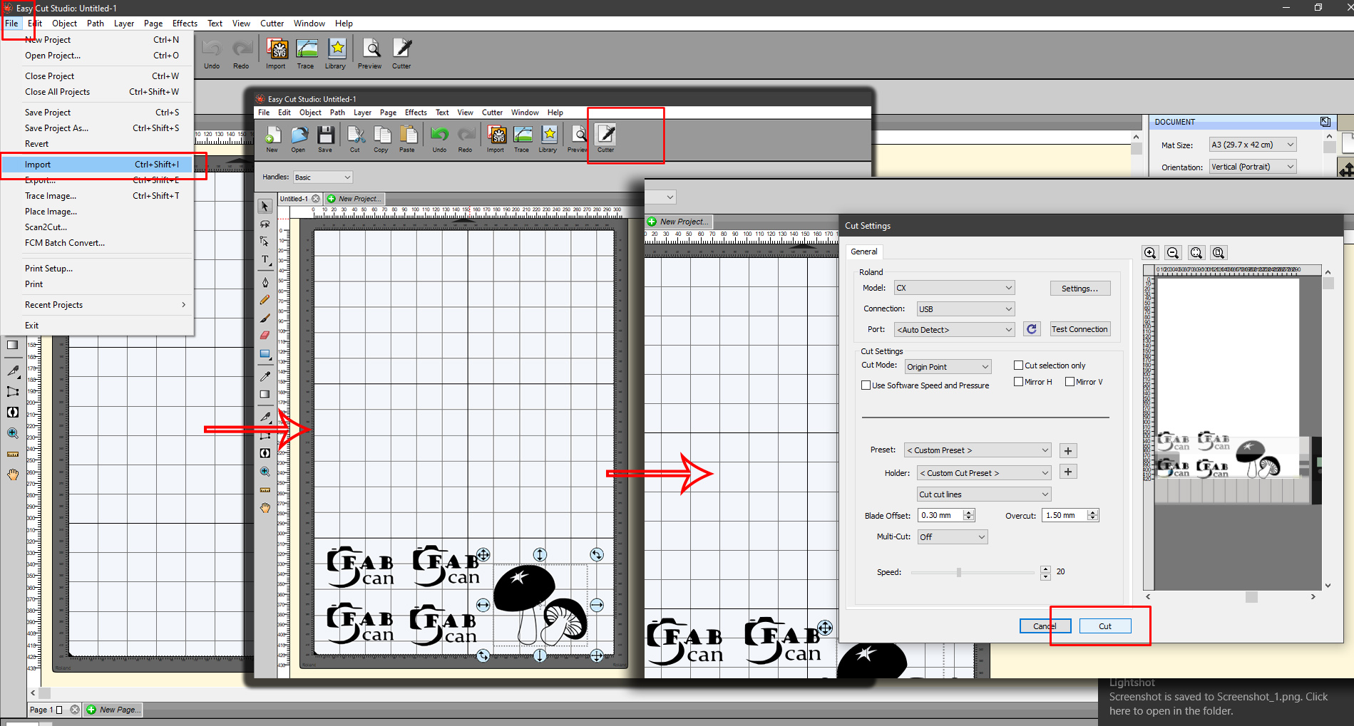
Perform Cutting by clicking on Cut
The final result is as shown below:
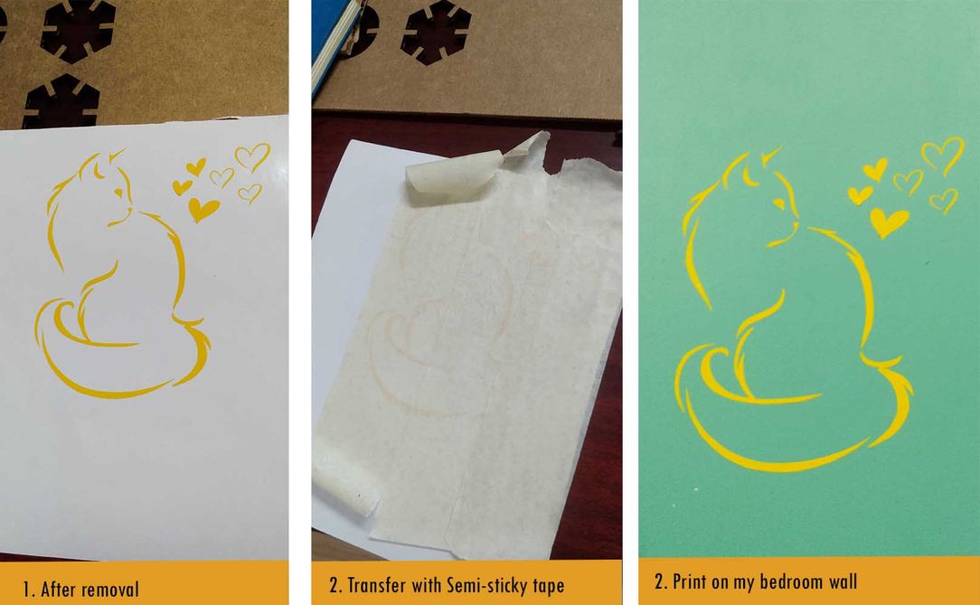
I used the masking tape to transfer the final cuts after removing the unwanted parts.