
Networking & Communications
Group Assignment
Group Assignment:
send a message between two projects
The group work that our group has done can be seen here
Individual Assignment:
design, build, and connect wired or wireless node(s) with network or bus addresses
I have many things to learn this week. The main goal of this weeks assigment is to create a network using my PCB boards using a wired or wireless connection. I want to work with wireless communication devices like bluetooth module, I plan to go with I2C wired protocol. SInce I couldn't understand the lectures, I referred Abhinav Ajith's Page. He has given a clear discription on this assignment with Bluetooth module networking.
Understanding Embedded Communications.
According to Gadgetronicx,
In Embedded systems, communication protocols are the ways to efficiently exchange data between devices.
Communication may be in one direction or in both directions.
Broadly, it can be classified as Synchronous and Asynchronous communication. Different types of communication
are listed below:
1. Parallel: It transfer multiple bits at the same time usually in buses of data
transmitting across 8, 16, or more wires. Data is transferred in huge, crashing waves of 1’s and 0’s.An 8-bit data bus,
controlled by a clock, transmitting a byte every clock pulse. 9 wires are required for the communication purposes.
2. Series: Serial interfaces stream their data one single bit at a time.
These interfaces can operate on as little as one wire and usually never more than four. Example of a serial interface,
transmitting one bit every clock pulse. For communication 2 wires are required
3. Asynchronous: Asynchronous means that data is transferred without support
from an external clock signal. This transmission method is perfect for minimizing the required wires and I/O pins.
4. Synchronous: A synchronous serial interface always pairs its data line(s) with a
clock signal, so all devices on a synchronous serial bus share a common clock.
This makes for a more straightforward, often faster serial transfer, but it also requires at least one extra wire between communicating devices.
Examples of synchronous interfaces include SPI, and I2C.
Communication Protocols
According to EL-Pro_Cus The proper descriptions of digital message formats as well as rules are known communication protocols. The main function of these protocols is to exchange messages from one computer system to another. These protocols cover error detection & correction, signaling, and authentication. They can also explain the semantics, syntax & brings analog & digital communications together. Basically, from my understanding, it is a set of rules that defines the share of information from one device to another. Communication Protocols can be classified as shown below:
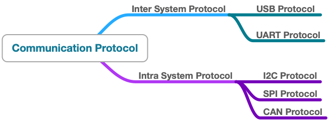
Inter-System Protocol
The inter-system protocol using to communicate the two different devices. Like communication between computer to microcontroller kit. The communication is done through an inter bus system.
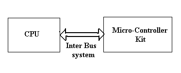
The different categories of intersystem protocol are:
1. UART Protocol
2. USART Protocol
3. USB Protocol
Intra-System Protocol
The site mentions that the Intra system protocol is used to communicate the two devices within the circuit board. While using these intra system protocols, without going to intrasystem protocols we will expand the peripherals of the microcontroller. It is more data secured and economical to use this system.
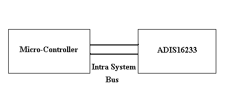
The different categories of intra-system protocol are:
1. I2C Protocol
2. SPI Protocol
What is I2C (Inter-Integrated Circuit) Protocol
I2C combines the SPI and UARTs protocols. This is with I2C, you can connect multiple slaves to a single master and you can have multiple
masters controlling single, or multiple slaves.
This is really useful when you want to have more than one microcontroller
logging data to a single memory card or displaying text to a single LCD.
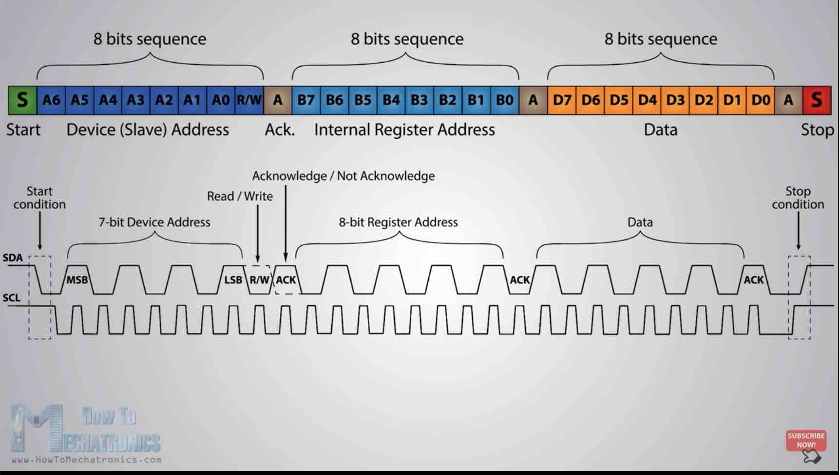
I2C is a serial communication protocol,
so data is transferred bit by bit along a single wire (the SDA line). I2C only uses two wires to transmit data between devices:
SDA (Serial Data) - The line for the master and slave to send and receive data and SCL (Serial Clock)
- The line that carries the clock signal.
I2C is a serial communication protocol and data is transferred bit by bit along a single wire of the SDA line. I2C is synchronous, so the output of bits is synchronized to the sampling of bits by a clock signal shared between the master (which controls the clock signal) and the slave.
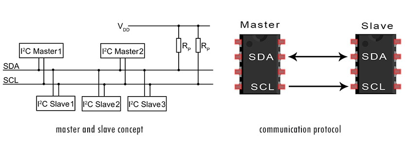
The data signal is transferred in sequences of 8 bits. After a start condition, the first eight bits sequence occurs, which indicates the address of the slave where the data is being sent. After each 8 bit sequence follows a bit called acknowledge. After the first acknowledge bit comes another addressing sequence for the internal registers of the slave device. Next follows the data sequences until the data is completely sent. It ends with the stop condition.
SPI Protocol
According to Electronic hub , Serial Peripheral Interface or SPI is a synchronous serial communication protocol is a protocol that provides full–duplex communication at very high speeds. SPI is a master–slave type protocol that provides a simple and low cost interface between a microcontroller and its peripherals.
One unique benefit of SPI is the fact that data can be transferred without interruption. Any number of bits can be sent or received in a continuous stream.
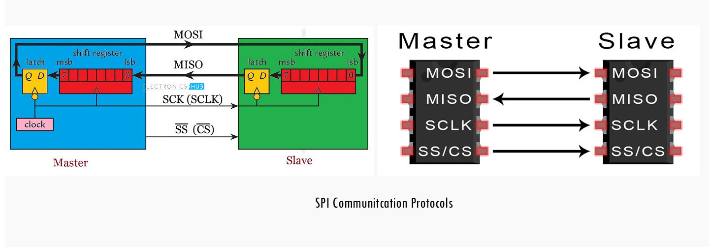
Master–Out:Slave–In or MOSI is the data generated by the Master and received by the Slave. Hence, MOSI pins on both the master and slave are connected together.
Master–In:Slave–Out or MISO is the data generated by Slave and must be transmitted to Master.
Since the clock is generated by the Master, the flow of data is controlled by the master. For every clock cycle, one bit of data is transmitted from master to slave and one bit of data is transmitted from slave to master.
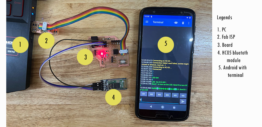
HC05 Bluetooth Module as a Networking Device
I am using the board I have designed for my final project. For this assignment, I learnt about bluetooth HC05 module. This website gives a very good information about the module. The HC-05 is a popular bluetooth module which can add two-way (full-duplex) wireless functionality to your projects.
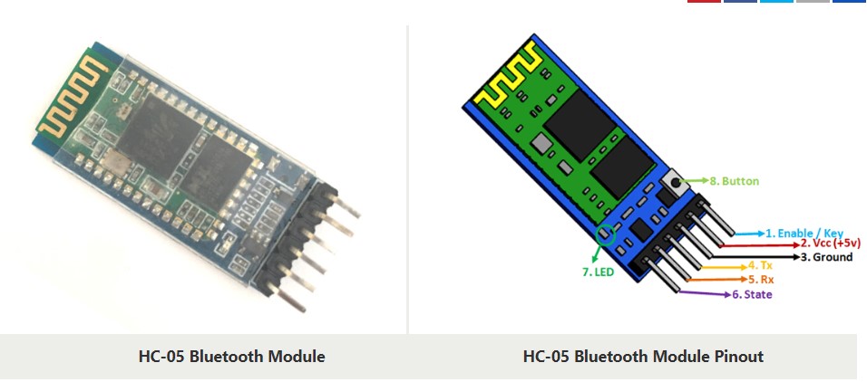
HC-05 Pinout Configuration
|
Pin Number |
Pin Name |
Description |
|
1 |
Enable / Key |
Used to toggle between Data Mode (set low) and AT command mode (set high). By default it is in Data mode |
|
2 |
Vcc |
Powers the module. It must be connected to +5V Supply voltage |
|
3 |
Ground |
Ground pin of module, must be connected to system ground. |
|
4 |
TX – Transmitter |
Transmits Serial Data. Everything received via Bluetooth will be given out by this pin as serial data. |
|
5 |
RX – Receiver |
Receive Serial Data. Every serial data given to this pin will be broadcasted via Bluetooth |
|
6 |
State |
The state pin is connected to on board LED, it can be used as a feedback to check if Bluetooth is working properly. |
|
7 |
LED |
Indicates the status of Module
1. Blink once in 2 sec: Module has entered Command Mode |
|
8 |
Button |
Used to control the Key/Enable pin to toggle between Data and command Mode |
In brief, the following is the working condition for the module.
1. Operating Voltage: 4V to 6V (Typically +5V)
2. Operating Current: 30mA
3. Range: less than 100m
4. Works with Serial communication (USART) and TTL compatible
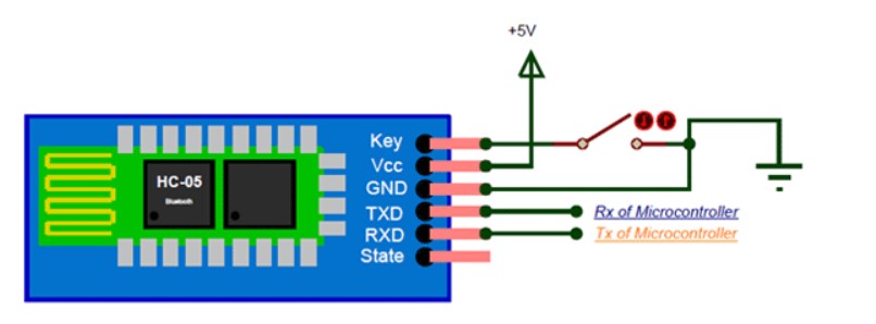
Programming HC05 Bluetooth Module
I want to test the bluetooth module and program it using fabISP and my final project board.
I referred teachmemicro.com to understand how to program
using Arduino to control the LED in my board using the terminal of the phone. I got a very good knowledge on how to make the connections
and test the module.
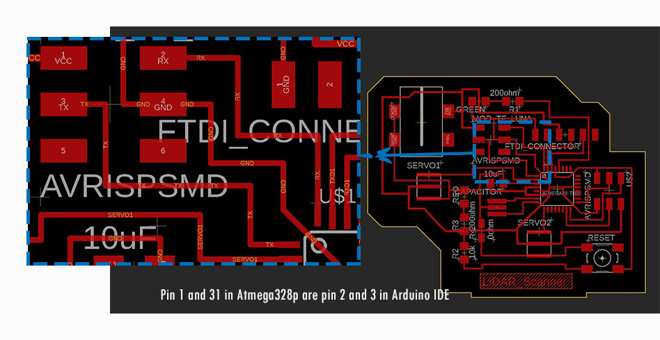
I have designed my project board using Atmega328p microcontroller.
The connections are as shown below:
For bluetooth module, I need Rx and Tx pins which are in pin 1 and 31 in my board. The corresponding pins are 2 and 3 in arduino IDE.
Before programming, select the microcontrollers by:
Go to Tools ---> Boards ---> Atmega controllers ---> Atmega/atmega328p
Choose Atmega238p
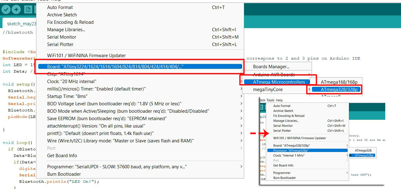
Choose Clock external 20 MHz and Programmer as USBtinyISP.
Load the following codes:
                            //bluetooth hc05 with terminal via serial communications


                            #include <SoftwareSerial.h> //Importing softwareSerial library
                            SoftwareSerial Bluetooth(2,3); // Rx and TX: my pin number 1 and 32 are Rx and Tx which correspons to 2 and 3 pins on Arduino IDE
                            int LED = 19; // the on-board LED
                            int Data; // the data received

                            void setup() {
                              Bluetooth.begin(9600); //bluettooth is set up
                              Serial.begin(9600);
                              Serial.println("Waiting for command...");
                              Bluetooth.println("Send 1 to turn on the LED. Send 0 to turn Off");
                              pinMode(LED,OUTPUT);

                            }

                            void loop() {
                              if (Bluetooth.available()){ //wait for data received
                                Data=Bluetooth.read();
                                if(Data=='1'){
                                  digitalWrite(LED,1);
                                  Serial.println("LED On!");
                                  Bluetooth.println("LED On!");
                                }
                                else if(Data=='0'){
                                   digitalWrite(LED,0);
                                   Serial.println("LED Off!");
                                   Bluetooth.println("LED  On D13 Off ! ");
                                }
                                else{;}
                              }
                            delay(100);
                            }
Note that I have LED on corresponding pin 19 in my board. The result is as shown here: You can see that when I press 1, it commands my LED to turn ON and when I sent zero, it commands my LED to turn off.