
mechanical Design, Machine Design
Assignment:
- design a machine that includes mechanism+actuation+automation+application
- build the mechanical parts and operate it manually
- document the group project and your individual contribution
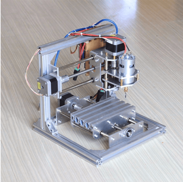
For our group, we designed PCB milling machine and it can be seen here here
Group documentation can be viewd here in Sonam's page. I have also mentioned herewith for my own personal reference in the future
Software Used
Autodesk Fusion 360: Making designs
Aspire: Controlling the Shopbot
DXF to G-code converter: Controlling the machine
Visual Studio: For Documentation
Idea Conception and Planning
The idea came from the problem when milling our PCB on the current PCB milling machine.
The bed level on the current Roland- SRM20 machine that we are using had become uneven.
Due to this we faced a number of problem when milling our PCB for output week.
\This also caused for the loss of a number of copper plate. Thus, we thought why not try to create a PCB
milling machine for this week's machine making week.
Once we all agreed on the idea, the next step was to explore on how to build the machine. Since we do not
readily get the electronic components in our country, we had to ensure that all the electronics we required were
available in the lab. For this we had to dismantle a couple of previously made machines.
We gathered all the electronics we required and then started with the work.
Our group had 7 members, thus we divided the tasks for efficiency.
Two people were allocated for designing the components, 3 for electronics and 2 for documenting the entire process.
For the assembly and testing the machine, we all worked together. We referenced our work as shown below:
Design of Parts
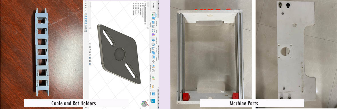
Initially we planned to 3-D print majority of the components but we realsized that the 3-D printer available at out lab was quite small and had the capicity to print only models with maximum of 180mm dimensions. Hence, we cut the bed for the milling machine on the CNC and the body frames using circular saw. For the machine body, we used Alumnium frames and polymer slabs which were cut using circular saw. For the bed, we used wood and cut it using CNC. However, for smaller components such as the cable holders and rod holder we 3D printed them.
Electronics
For the machine controller, we used Arduino Mega as the microcontroller. Arduino Mega Motor Shield was used to connect the motor driver to the microcontroller. We used 3 moter drivers to control the X,Y and Z axis

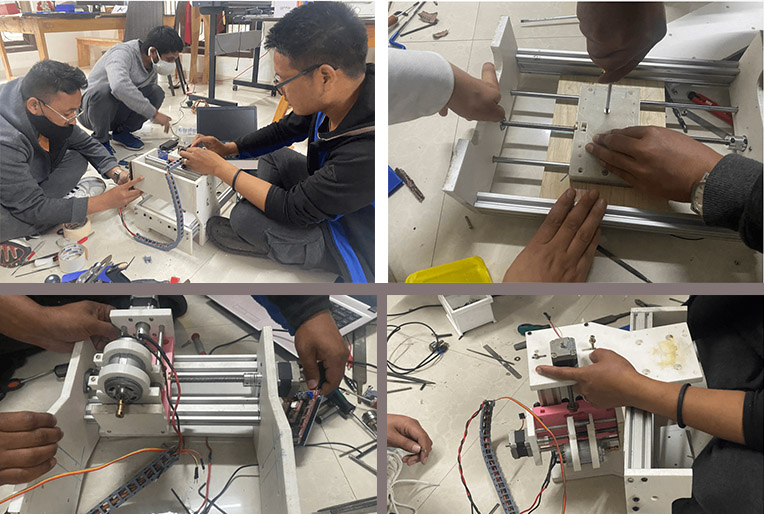
Machine Assembly
Pictorial representation of machine assembly can be seen below:
Machine Control
For controlling the machine we used G-Code. We downloaded an software called dxf2gcode which converts 2D dxf drawings to CNC machine compatible G-Code.

Testing of Prototype
Once the machine was assembled, we tested the machine. There were 3 major testing we carried out;
XY-axis test
Z-axis test
Bed allignment test
We tested the XY-axis, once the bed was assemnled. We found that the supporting rods were not alligned with the slot bearings, thus we used filers to recitfy that. Next, we tested the Z-axis and bed-allignment and made the necessary changes to recify those issues.
Final Working
Final working is documented in our machine design work homepage and can be referred here.