
Week 13
- Category: Networking and Communications
- Sessions Date:
- Assignment:
- Group Assignment
Sending a message between two projects- Individual Assignment
Connected ESP2 to Wifi
Week Assignment
Communication ProtocolsThere are formal description/specifications of the formats of messages and rules. These are needed in order to exchange the data messages in or between the systems of computers. There are extremely when it comes to telecommunication systems and other related systems. These create certain consistently and universally accepted standards for sending and receiving messages.
- Authentication
- Detection of Errors
- Signalling
- Correctness
Asynchronous and Synchronous Protocol
Synchronous Transmission
Synchronous data transmission is just a technique of data transfer where a continuous stream of data signals is supplemented with timing signals (produced through an electronic clock) to guarantee that the transmitter and receiver are in sync (synchronized). The data is transferred in fixed-time interval chunks (called packets or frames)
When huge volumes of data must be transported swiftly from one point to another, synchronous transmission mechanisms are utilized. The synchronous connection's speed is achieved by transmitting data in huge chunks rather than individual characters.
Transmission that is synchronous uses clock signals integrated into each component to synchronize transmission rates both at receiving and sending ends of the transmission. After that, a continuous stream of data is transferred between both the two nodes.
The following are some features of synchronous communication:
- There have been no gaps in the transmission of characters.
- Modems or even other devices at every end of the link provide timing.
- The data is preceded by special syn characters.
- The syn characters are utilized for timing reasons between data blocks.
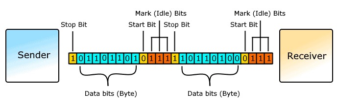
Asynchronous transmission, on the other hand, works in bursts and requires a start bit before every data character and a stop bit at the conclusion to indicate the receiver where it begins and finishes. The word asynchronous refers to the process of encoding transmitted data with start and stop bits that identify the start and the end of each letter.
The following is a list of characteristics specific to asynchronous communication:
- Each character is preceded by a start bit and followed by one or more stop bits.
- Gaps or spaces between characters may exist.
Wired and Wireless Network
Wired Network: As we all know, the term "wired" relates to any physical media comprised of cables. Copper wire, twisted pair cables, and fiber cable are all possibilities.Hardware must be used to link two communicating devices in wired communication. This medium will be used by the two devices to transmit and receive information. The need for additional intermediary devices like amplifiers, repeaters, and routers will depend on how close between the two communicating devices are. Due to the fact that wireless communication is more susceptible to environmental disturbances, wired communication is more dependable.
Wireless Network: "Wireless" refers to media that is not wired and is composed of electromagnetic waves (EM Waves) and infrared waves. All wireless gadgets will have antennas or sensors. Wireless gadgets include cell phones, wireless sensors, Remote controls, satellite disc receivers, and computers with WLAN cards. A wireless network communicates using radiofrequency waves instead of cables.When using the air as a communication conduit between two devices, wireless communication is possible. The environment and the weather have an impact on these communication techniques. The kind of communication protocol and standards in use also affect the communication's range. Short-range, confined-area communication technologies like WiFi and Bluetooth are available.
- SPI SPI is an abbreviation for serial peripheral interface. Motorola created one of the serial communication protocols. SPI protocol is also known as a 4-wire protocol. It necessitates the use of four wires: MOSI, MISO, SS, and SCLK. To communicate between the masters and slave devices, the SPI protocol is employed. The clock is initially configured by the master using a frequency.
- I2C Protocol Once the addresses match, communication between the master and the slave device begins, with data being transmitted and received. The transmitter delivers 8-bit data, while the receiver responds with a 1-bit acknowledgement. Whenever the conversation is over, the master triggers the stop condition. Philips Semiconductors invented the I2C bus. Its initial objective was to give a simple means of connecting the CPU to peripheral chips. In embedded systems, peripherals are frequently attached to the microcontroller via memory-mapped devices. I2C just takes two wires to connect all peripherals to the microprocessor. These active wires, known as SDA and SCL, are bidirectional. SDA is a serial data line, and SCA is a serial clock line.
- USART USART is an acronym that stands for universal synchronous and asynchronous transmitter and receiver. It is a two-wire serial communication protocol. The data cable signal lines are denoted by the letters Rx and TX. This protocol is being used to send and receive data byte by byte, accompanied with clock pulses. It is a full-duplex protocol, which means it transmits and receives data at multiple board rates at the same time. This protocol is used by many devices to connect with the microcontroller. Ex:-Telecommunications. In USART, data is sent via data packets, which typically include 8 data bits, 2 start bits, and 1 parity bit for error-correction. Data in USART will be sent as data frames or data packets. A start bit precedes the data bits in a data frame, which are subsequently followed by the parity and stop bits. The majority of microcontrollers offer options for configuring the data frame's structure and bit count. This protocol is used for serial communication via the serial port between the Arduino and PC via USB.
- USB USB is an abbreviation for universal serial bus. It is once again a two-wire serial communication protocol. The data cable signal channels are denoted by the letters D+ and D-. This protocol is used to exchange data with system peripherals. The USB protocol is used to serially send and receive data between the host and peripheral devices. USB communication necessitates the use of driver software that is dependent on the system's operation. USB devices may transport data over the bus without the host computer's intervention. Nowadays, most devices communicate with the USB protocol utilizing this manner. A computer, for example, may use USB to interact with an ARM controller.
- VCC: For power supply
- GND: To close the circuit
- D+: Data Transfer differential line
- D-:Data Recieve Differential Line
- Ethernet Ethernet is the most widely used networking technology for connecting LANs and WANs. With the rise of IoT, this protocol has become critical in Embedded systems. This data transmission has been revised several times over the years to improve its connection and speed. To allow Ethernet connectivity, Ethernet controller chips such as the WZ1500 are typically utilized in conjunction with standard microcontrollers. However, certain high-end microcontrollers, such as the STM32, will have some level of Ethernet protocol functionality. To transmit and receive data inside a network, such microcontrollers employ the MII or RMII protocol.
- RS-485 Protocol:
- TX+
- TX-
- RX+
- RX-
The master then pulls the chip choose button to select the specific slave device for communication. That particular gadget is chosen, and communication between both the master and that particular slave begins. The master only chooses one slave at a time. It is a communication protocol that operates in full duplex mode. In the case of bit transferring, 8-bit words are not limited.
For a number of examples in our tasks, we used the SPI protocol. The same protocol can be used for programming the Attiny board with Fab ISP. Through same procedure, we also program our board utilizing Arduino as ISP.
Depending on how it operates, the I2C protocol provides various data speeds. Data transfer rates of 100 kbit/s in normal mode and 400 kbit/s in full speed mode are both possible. I2C protocol is used by the LCD to receive and show data from a microcontroller. Each device in the I2C protocol has a unique address. When a master wants to send data to a slave, it uses the SDA pin to convey the address of the slave device that the message is meant for. Only the slave with the provided address will take this incoming data, which is followed by a Data frame.
USB protocol uses the pins below to function:
Data packets are used for every data transfer in a USB communication. A data packet typically consists of three parts: a token packet that contains information about the data type and device address. The actual data to be sent is then included in a datapacket, which is followed by an EOP signaling the end of the datapacket.
RS-485 is yet another protocol popular for connecting microcontrollers with external peripherals. This protocol comes in very handy when the data need to be transmitted for over hundreds of meters. Similar to Ethernet protocol most microcontrollers uses external chips like MAX485 to use this protocol. Using this protocol several devices can use the same interface and perform data exchange. More about RS-485 protocol here. These are the pins involved in RS-485 protocol.
A typical data frame of RS-485 comprises of start bits, receiver address, data bits and stop bits to indicate the end of transmission.
Wireless Connection
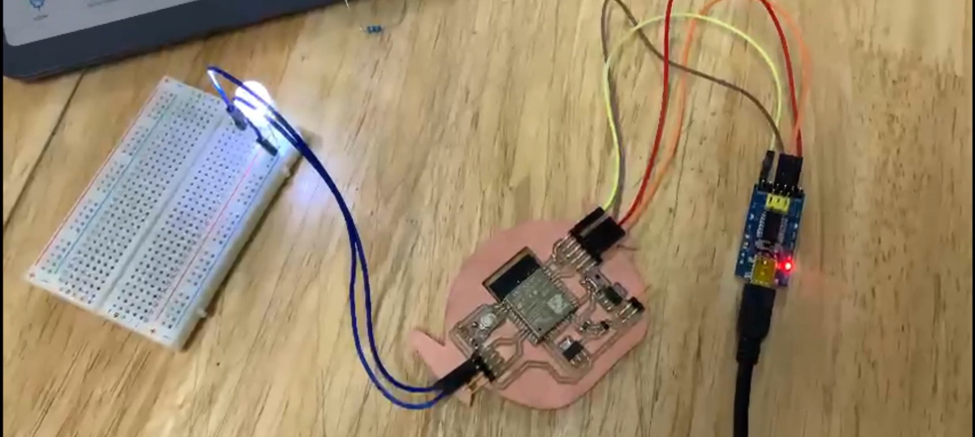
For this week am going to try wireless connection and see if I can control LED from the wifi. I am using the same board as that of the Output Week.
Since I was using ESP-32 as a microcontroller, I didnt have to make another board. Also esp library was already there in my Arduino Ide. After making my connections, I proceed for the coding.
Programming
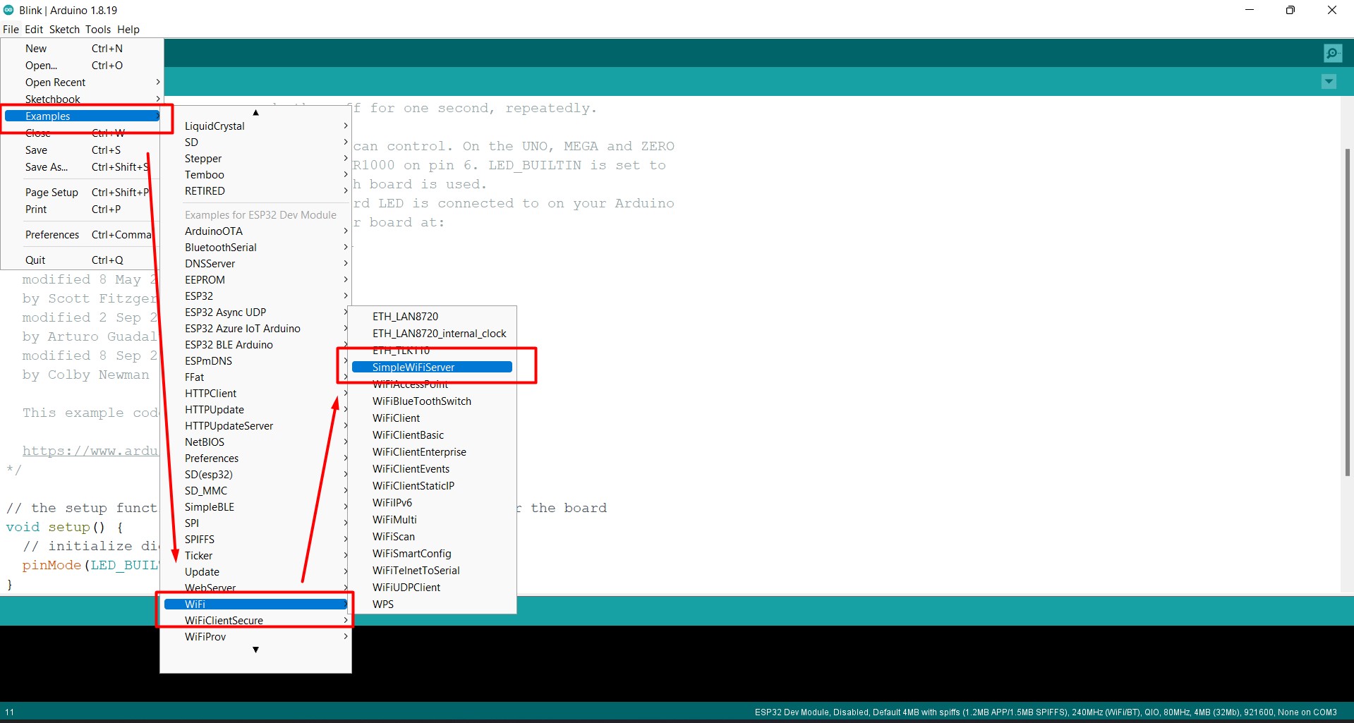
- Following are the steps taken while programming
- go to files >> examples >> wifi >> SimpleWifiServer
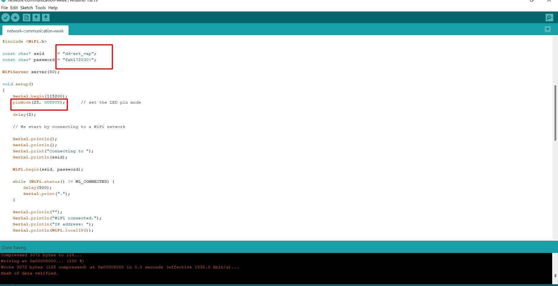
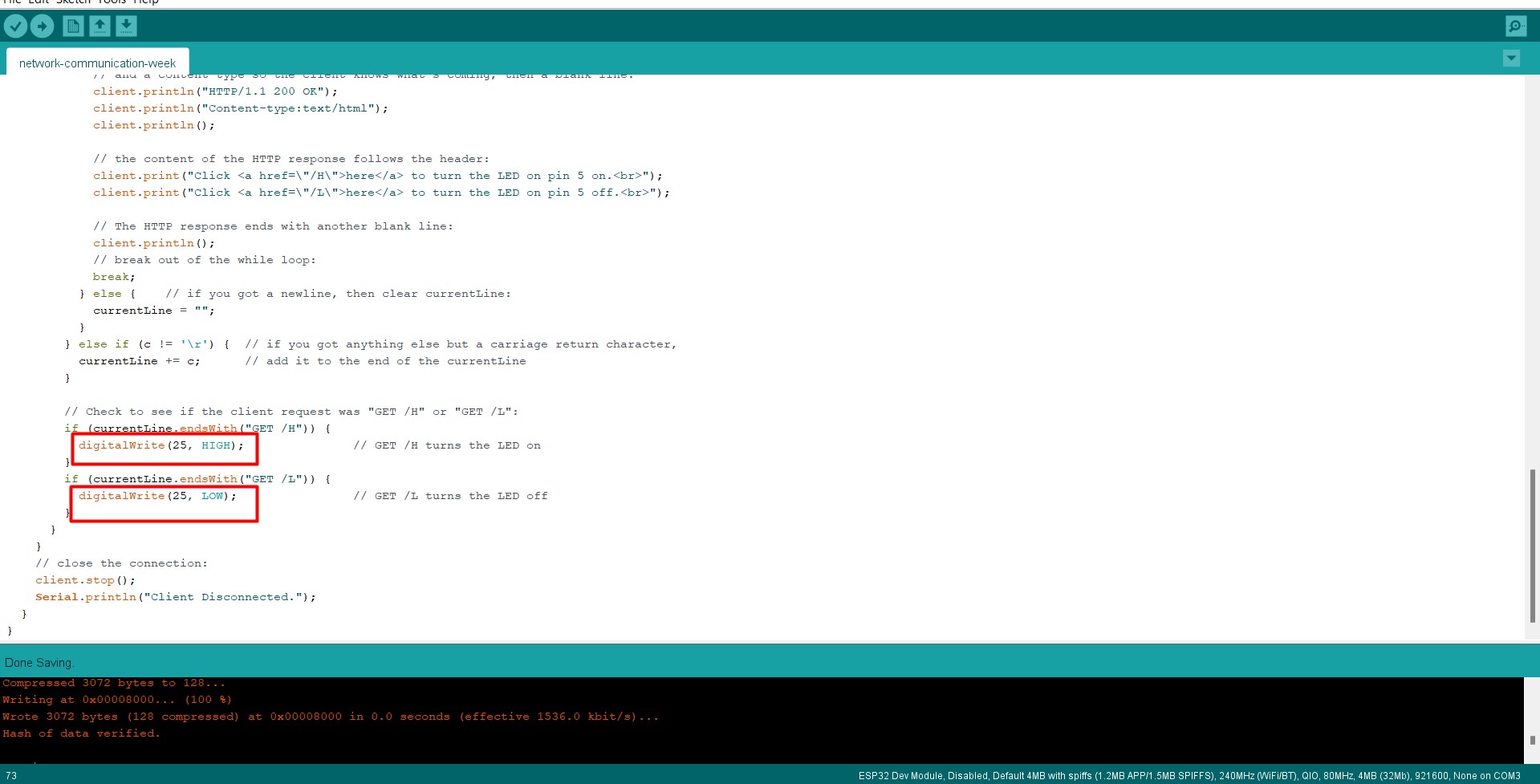
- Then I made the changes in the coding. I put labs wifi and its password. And changed the pinMode to 25.
- After that I cinserted the pinmode 25 in the following codes
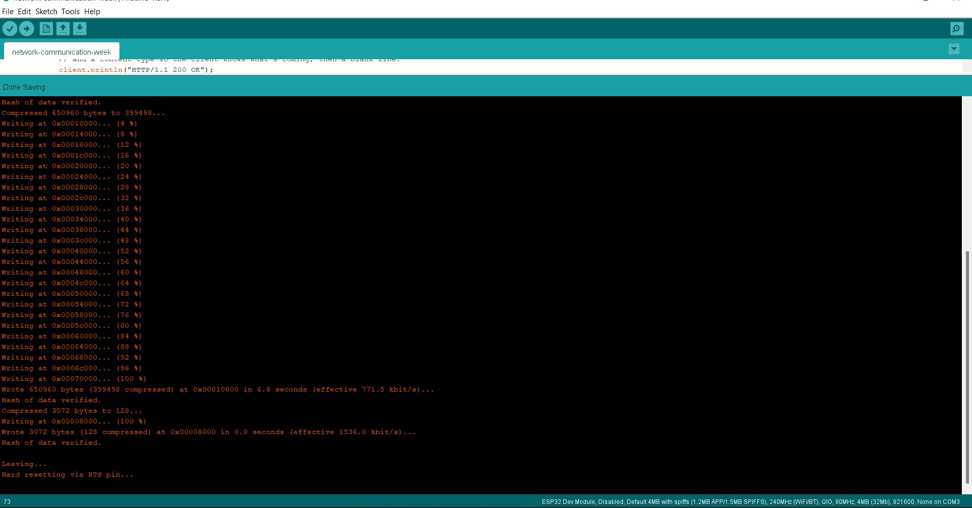
- Then I compiled the codes
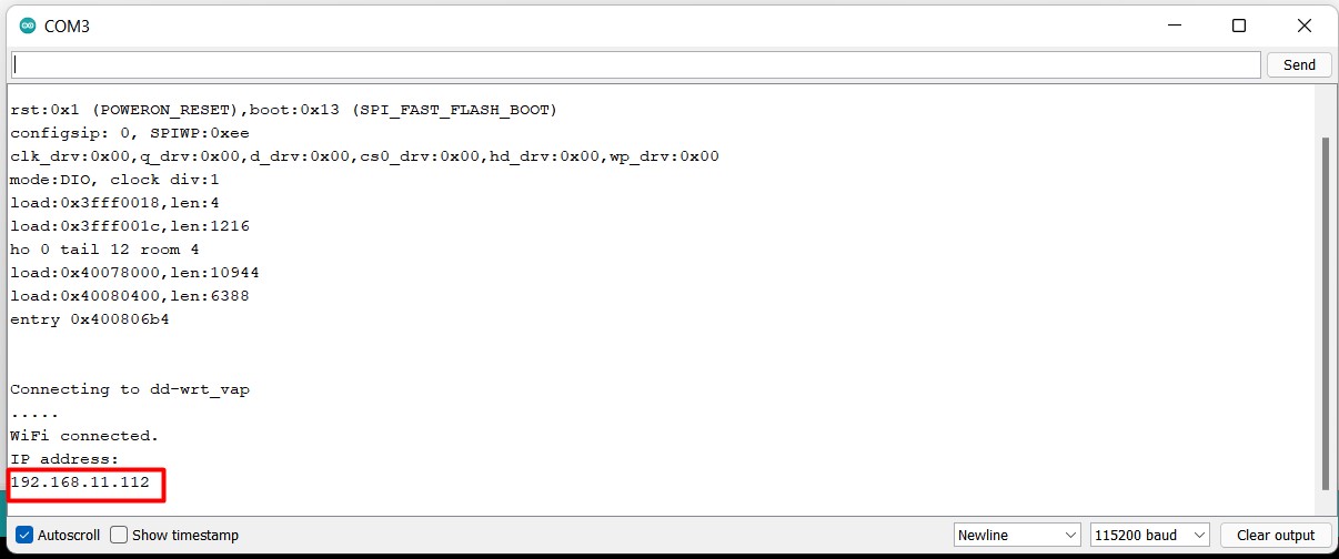
- Then go to the serial monitor and copy the IP Address
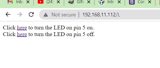
- After copying the IP Address, paste the IP address in a server and search. The option below will pop up. This is where you can control your LED through the wifi.
Hero Shot
Group Assignment
Click here for the group assignment.