
Week 10
- CategoryOutput Devices
- Sessions Date:
- Assignment:
- Group Assignment
- measure the power consumption of an output device
- Individual Assignment
- add an output device to a microcontroller board you've designed, and program it to do something
What is Output device?
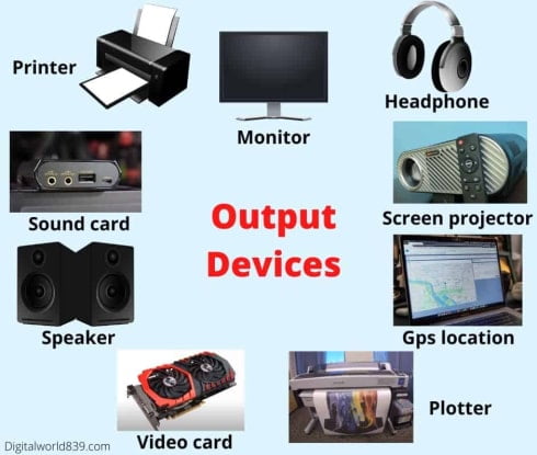
An output device is any hardware device used to send data from a computer to another device or user. Usually, most output peripherals are meant for human use, so they receive the processed data from the computer and transform it in the form of audio, video, or physical reproductions. output-device
Some of the examples of the output devices are LEDs,LCDs, speakers, earphones and etc...
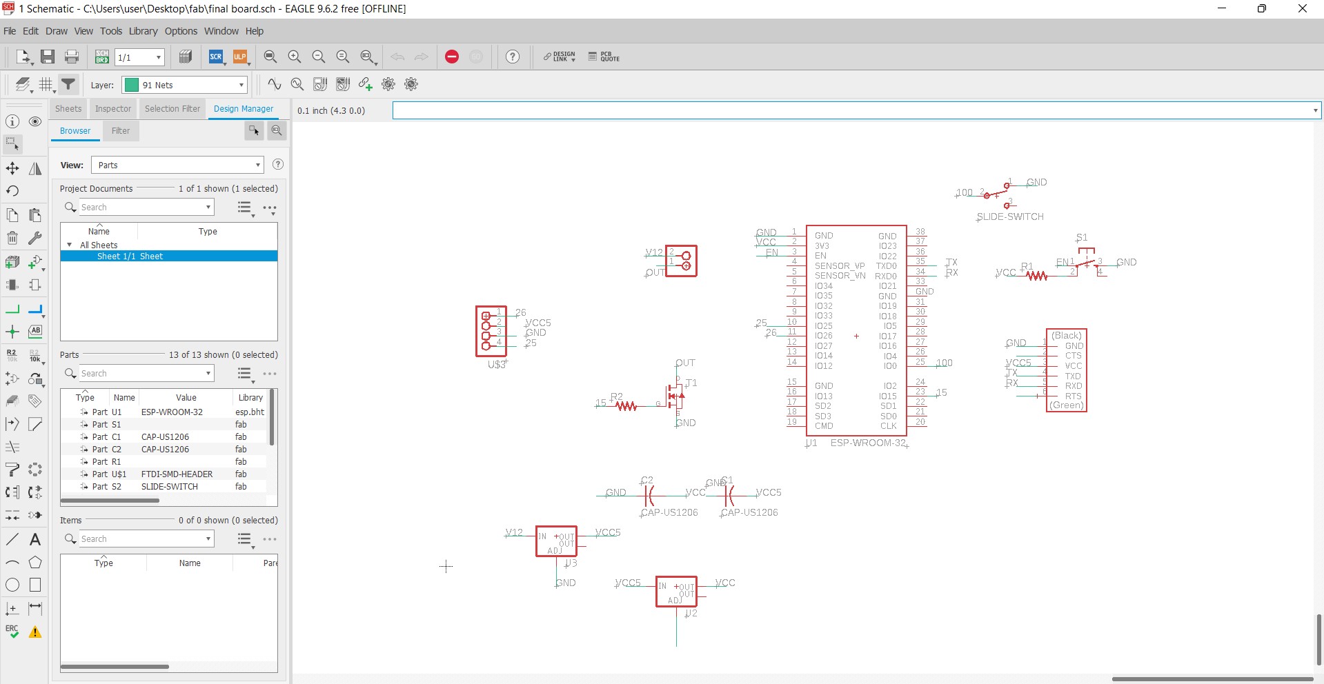
Schemetic Design
First Try
So for my output week,I am using an esp32 and mosfet to switch on and off LED which can later be used for my final project.I have also included a mosfet for switching my output device.For my Final project, I am going to make a wearable electronic ladies scarf, integrated with LEDS. So I need a board to program my LEDs.
- Components used
- ESP-32
- Tact Switch
- Regulator 5V
- Regulator 3.3V
- Mosfet N-channel 30V
- Resistor 10k Ohm
- Resistor 10.0 Ohm
- Slider switch 12V
- Capacitor 10uf x2
- 6 header pin
- 4 header pin
- 2 header pin
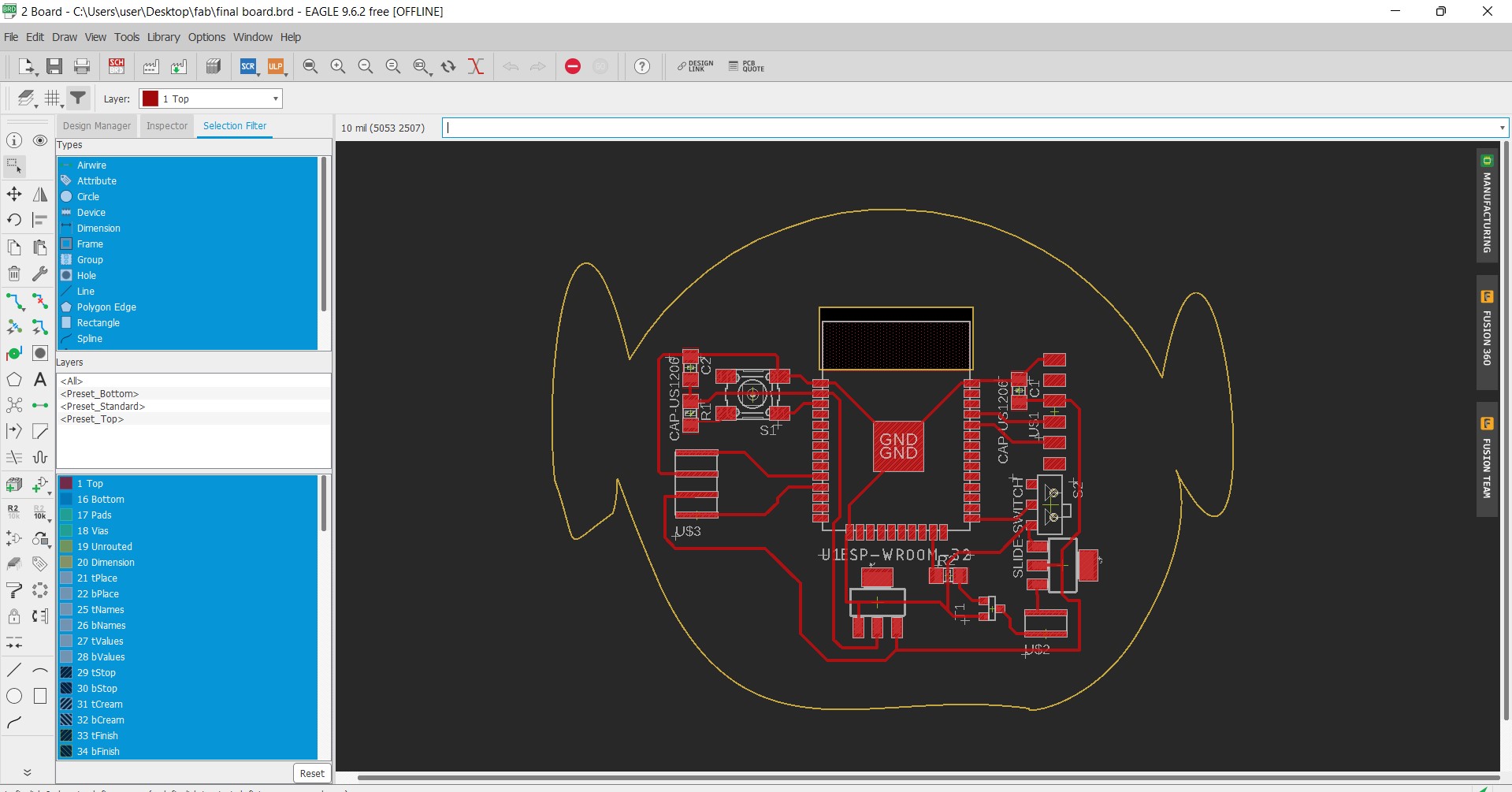
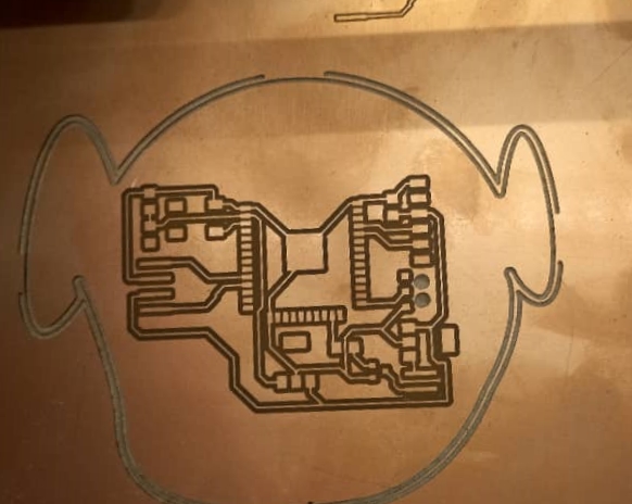
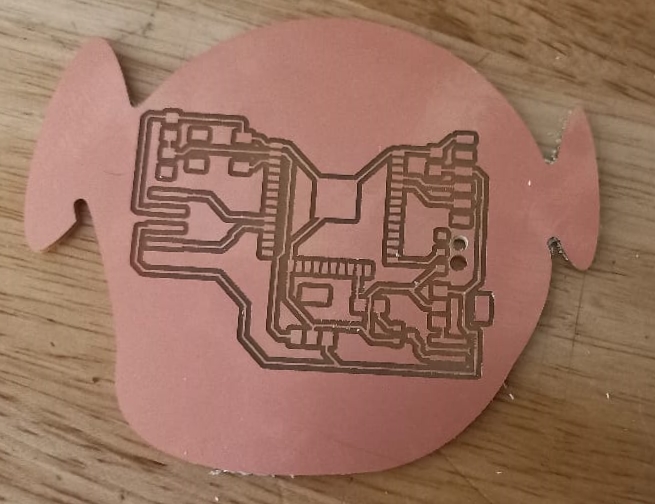
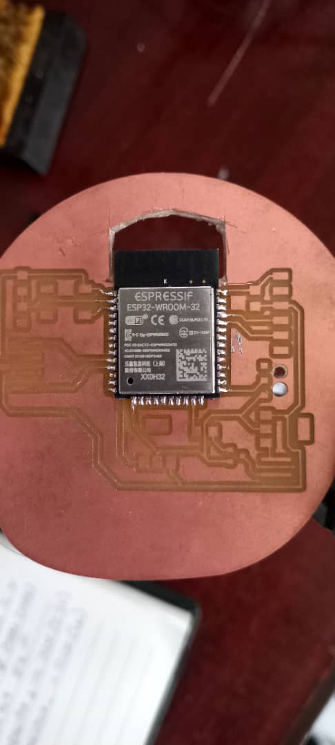
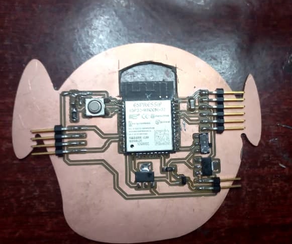
So after designing my board I mill it.
Soldering the components
The board came out well but now I have a problem. I forgot to keep hole for my ESP-32 antena.So I had to cut it mannually. And after that I soldered the components. I feel I have improved alot in soldering after all the practices.
Error Error Error
WHile soldering, I accidentally took the copper out from board. After enquiring my gurus and friends, they showed me ways to fix the board. With a help of soldering gun, I striped off the jumper wire and soldered it to the board and connected it. It worked!!!
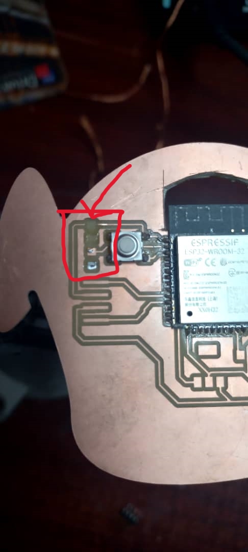
Below is an image of the process in fixing it.
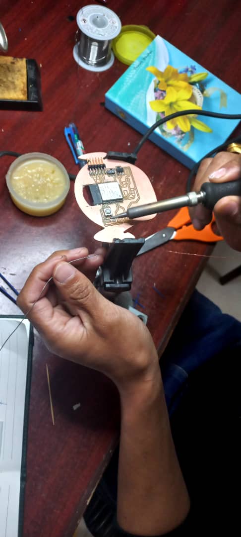
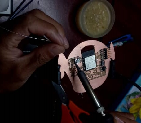
Soldered board
Another Error
While checking my board, it wasnt working. After checking the schemetic board, I have mistaken the foot print in both the regulators.I tried to fix the foot paths using wire as suggested by my friend but it was too complicated. So I decided to mill another board.
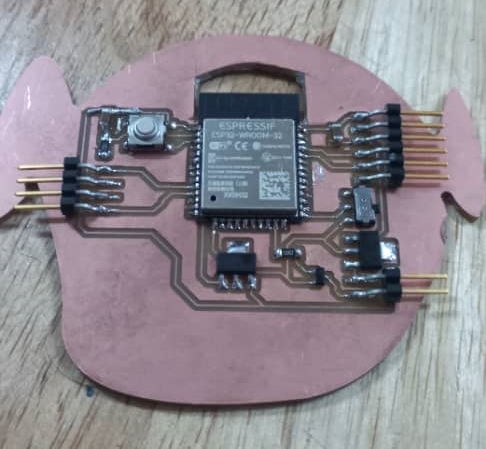
Second attempt
I changed the foot prints for my regualtors and this time I also kept hole for my ESP-32 antena.
And then I milled my board. Getting better using the PCB milling now. After milling the board I solderd my board and it went very well.
Testing and Programming the board
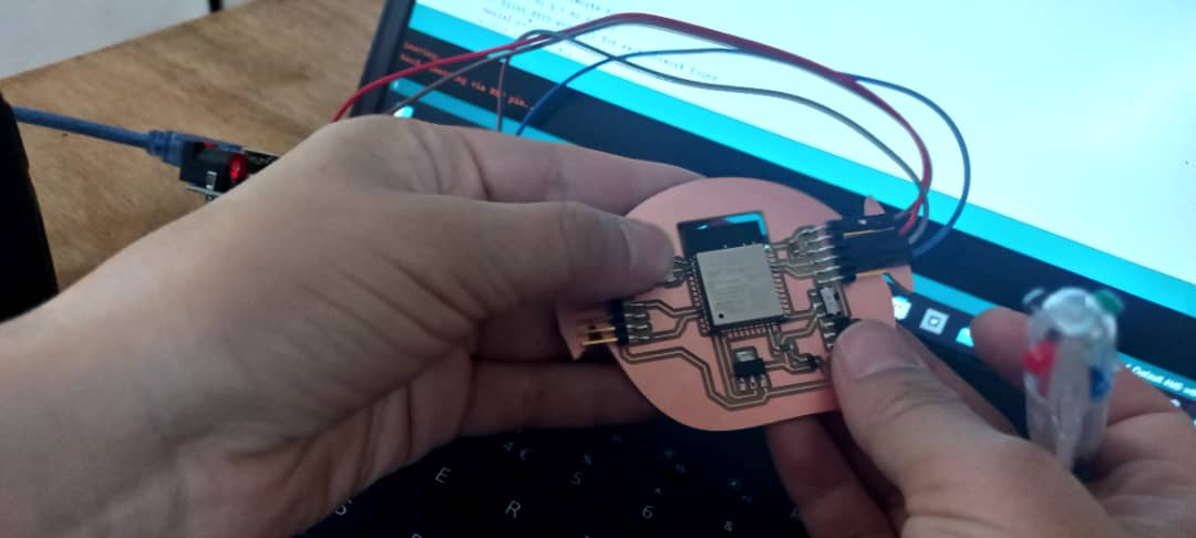
The next step after soldering the board is to program my board.I used Arduino as FDTI to program my ESP-32 board. I connected the ESP-32 to the arduino to check if its working and it worked!!!
After my board was functioning, I had to install the ESP-32 library.
- Steps followed
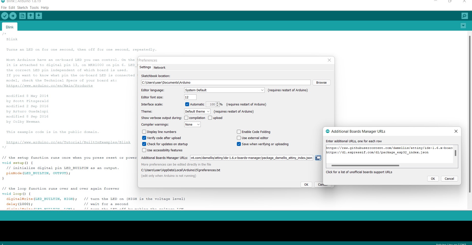
- go to file
- then to preferences
- And then on the "Additional Board Managers URL" paste "https://dl.espressif.com/dl/package_esp32_index.json"
- Since it had another link already present in the text box, I separate it using comma and keeping in new line
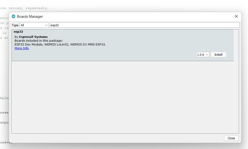
- Once its done, we have to go under tools and then to board manager where you can find the library.
- And then install it.
- Since I am using arduino as FDTI to program my ESP-32 board, I have to make arduino as
FDTI by either
- Shotting the EN and GND of the arduino
- Removing the IC of the arduino
- Loading the blank program to the arduino.
So I decided to load the blank program to the arduino and following is the code I used.
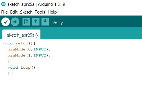
This is simple arduino code that makes RX and TX pin of the arduino as output pin. Load this code to arduino that you are going to use as FTDI.
Then I connected ESP-32 board to power supply and connect RX and TX pin of arduino with RXD 0 and TXD 0 pins of ESP32.
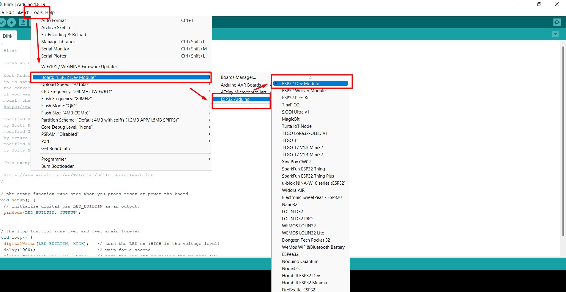
- Steps followed
- Go to tools
- Select Boards
- Then from Board manager select ESP32 Arduino
- ESP32 Dev Module
Then I changed the port to COM6 and then I comipiled.
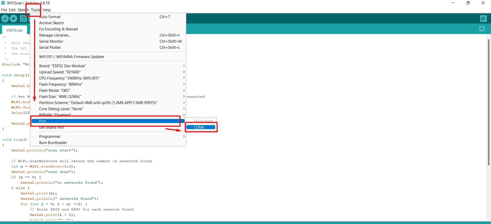
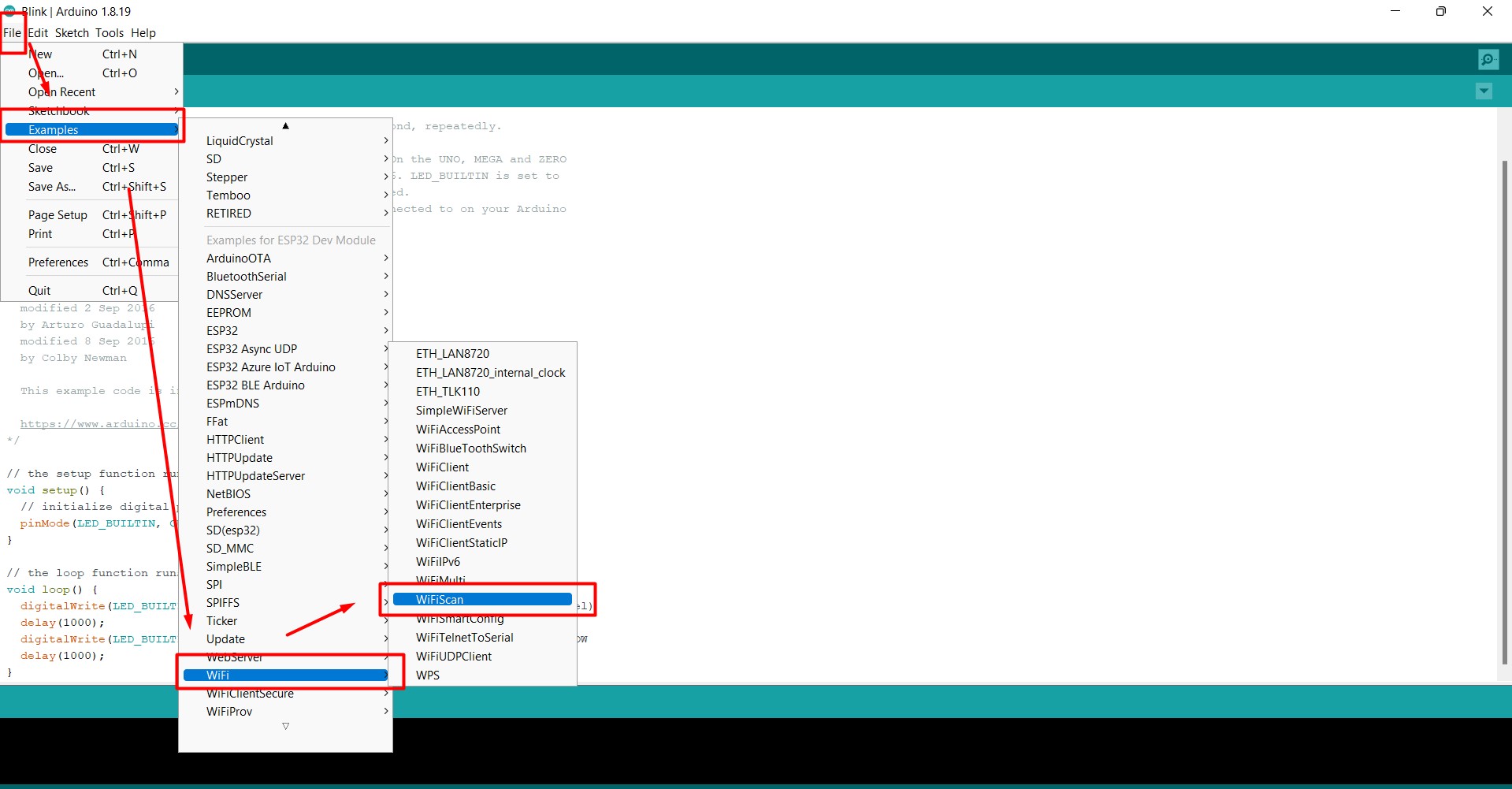
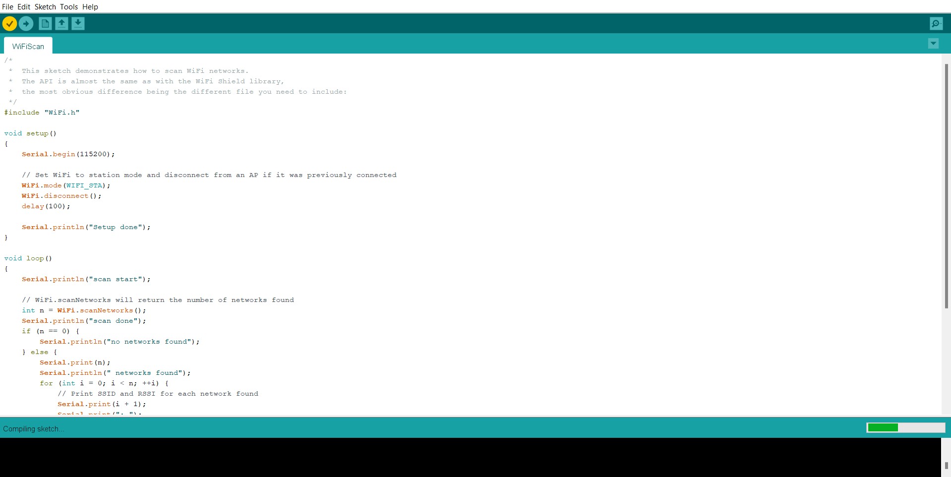
Then I went to Examples and then to wifi and WifiScan
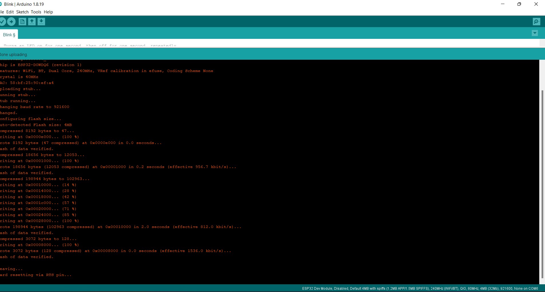
Press reset button on the board and then upload.
Go to the serial monitor-push the slide switch and back and press reset button
And then change the baudrate to -115200
Checking the Output
- I used the following components
- LED
- Resistor (100 Ohm)
- Bread board
- jumper wire
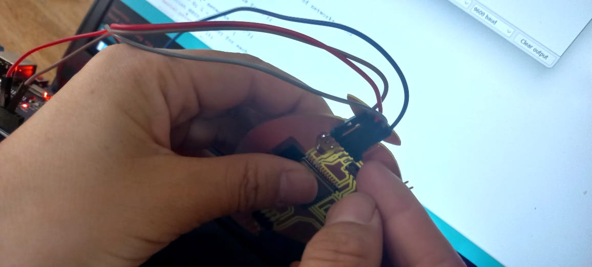
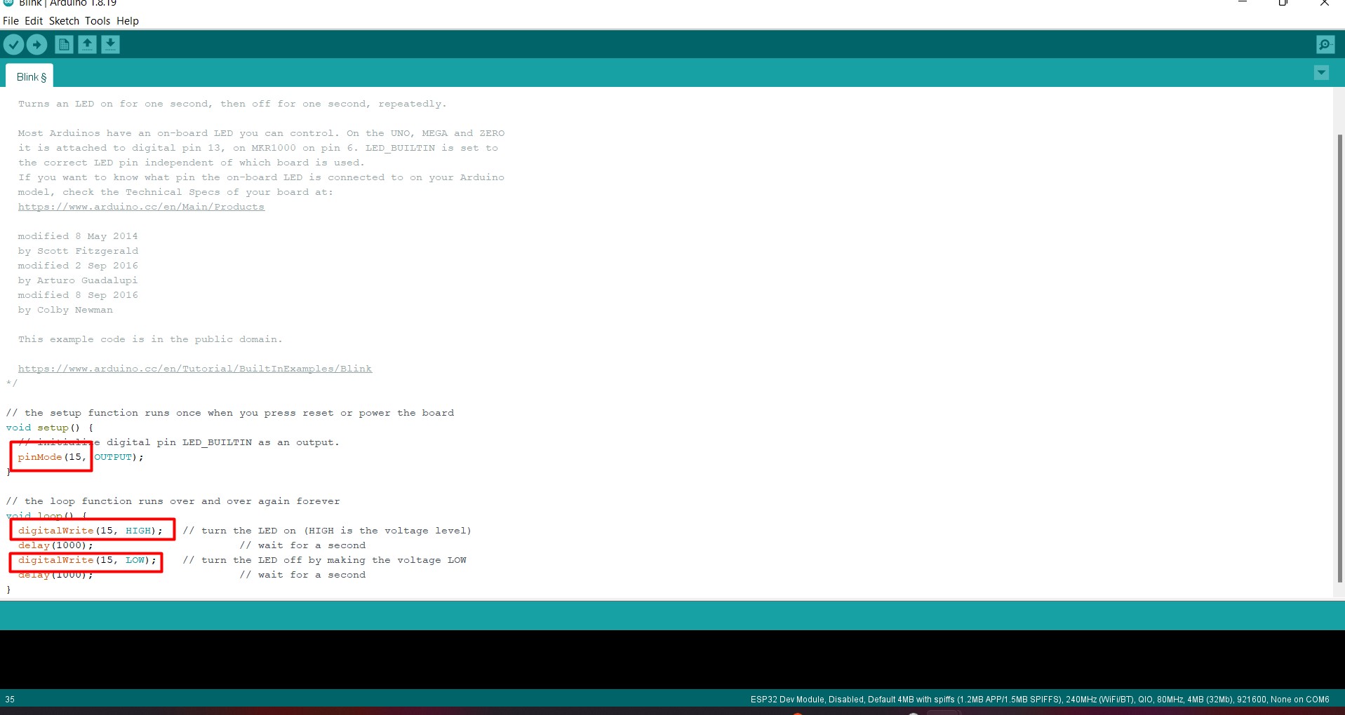
After that I load the blink code and changed the bluetin pin to 15 and uploaded.And it worked!!!
Hero-Shot
MOSFET
What is MOSFET?
MOSFET stands for Metal Oxide Silicon Field Effect Transistor or Metal Oxide Semiconductor Field Effect Transistor.
It is used for switching or amplifying signals. The ability to change conductivity with the amount of applied voltage can be used for amplifying or switching electronic signals. MOSFETs are now even more common than BJTs (bipolar junction transistors) in digital and analog circuits.
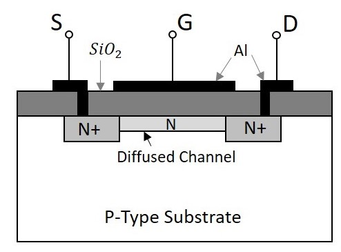
The following shows the construction of a MOSFET
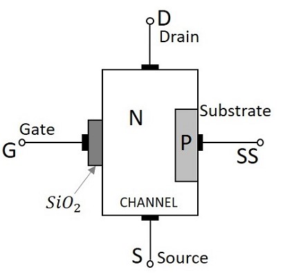
MOSFET Device Structure
- It has four-terminal
- Souce (S)
- drain (D)
- gate Terminal (G)
- body (B) terminals.
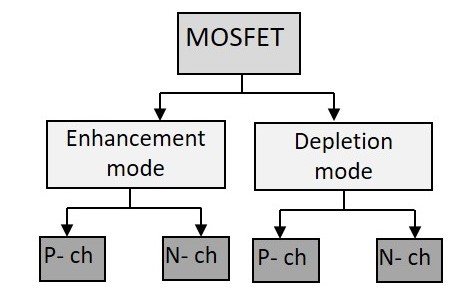
Classification of MOSFETs
The MOSFETs are categorized as shown in the following figure based on the building materials utilized and the type of operation.
For my final project I used the N channel MOSFET tok switch on and off my LED. Below is a diagram showing construction of a N Channel MOSFET.
LED Stripes
I am using LED stripes for my final project as one of the most important electronic component. It has been integrated with MOSFET to turn it ON and OFF. Following is an image of the LED I will be using. It requires a 5V power supply which will be supllied through a power bank.

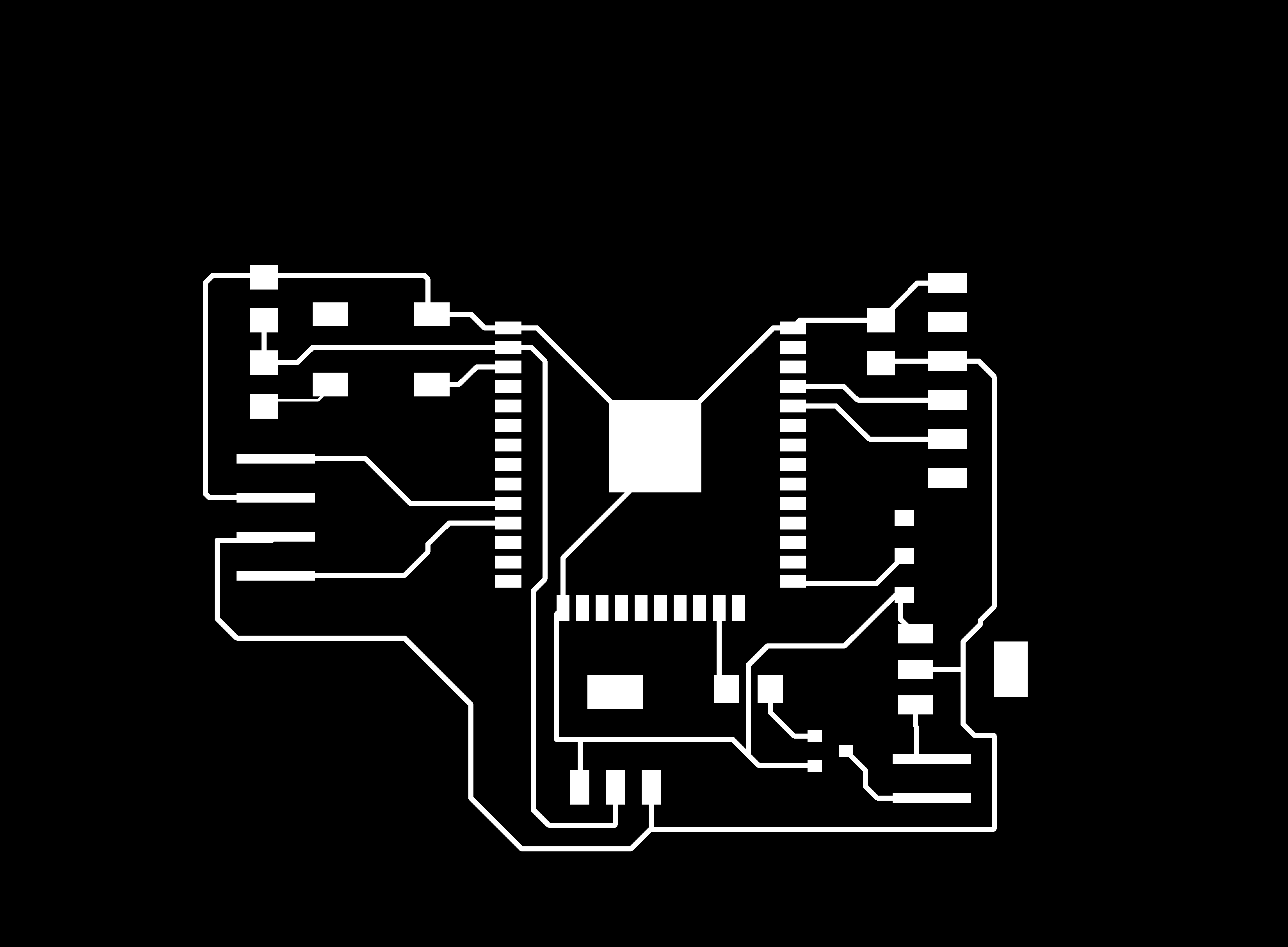
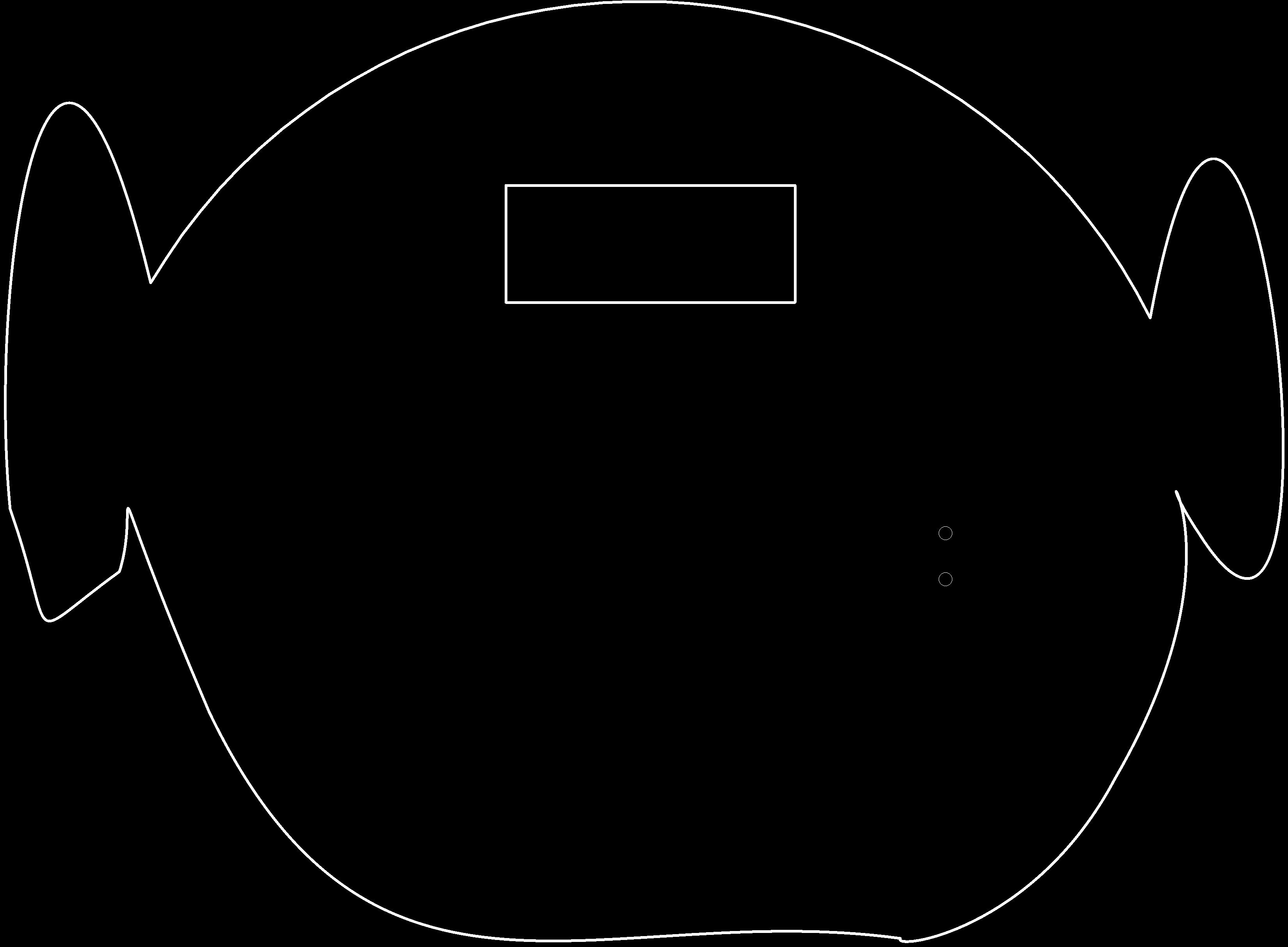
Files
Board tracesOutline traces 1
Board diagram in eagle