COMPUTER CONTROLLED CUTTING
CCC is the automated control of machining tools (such as drills, lathes, mills)
and 3D printers by means of a computer. A CNC machine processes a piece of
material (metal, plastic, wood, ceramic, or composite) to meet specifications
by following a coded programmed instruction and without a manual operator
directly controlling the machining operation.
CHECK LIST
Group assignment
- Characterize your lasercutter's focus, power, speed, rate, kerf, and joint clearance.
Individual assignments
- Link to the group assignment page
- Explain how I parametrically designed my files
- Document how I made my press-fit kit
- Document how I made my vinyl cutting
- Include original design files
- Include your hero shots
LASER CUTTING
Time to try new stuff.
LASER TECHNOLOGY
Laser cutting is a technology that uses a laser to slice materials.
It works by directing the output of a high-power laser through optics
The focused laser beam is directed at the material, which then either
melts, burns, vaporizes away, or is blown away by a jet of gas,
leaving an edge with a high-quality surface finish.
The following video shows how laser works.
UNDERSTANDING THE KERF
The laser burns away a portion of material when it cuts through,
this is known as the laser kerf and ranges from 0.08mm – 1mm
depending on the material type, properties and thickness and other
conditional factors like the focal length of the lens, pressure of
compressed air.
The following link shows in a detailed way how the laser works and
the considerations to take into account for the kerf.
How CO2 Laser Cutters work
This is a very usefull link which shows how much you will need to
account for the kerf within the drawing by adding or subtracting
the kerf width from your component dimensions on the most commonly
cut materials and thicknesses.
Understanding the kerf
UNDERSTANDING JOINT CLEARANCE
Joint clearance is the tolerance which two pieces have between one another
GROUP ASSIGNMENT - PREPARING THE LASER CUTTER
Before cutting the pieces, as a group assigment we had to set the parameters
on the lasser cutter:
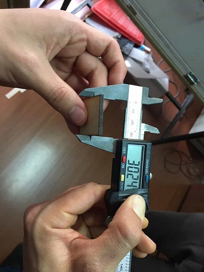
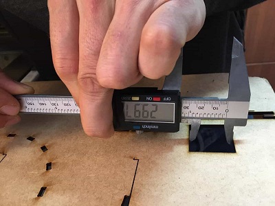
- We started measuring the material, for this exercise was a 3mm mdf
- Drew a square and cut it
- Measure the piece and the empty space to know the difference between both
- This gave us an idea of the kerf, for the firs try we left the kerf in 0.20mm
- With this on mind we modified our files and made the test
FIRST TRY
material: 3mm mdf
min power (%):68
max power (%):68
speed (mm/s):7
result: kerf 0.20mm, too loose, try a different kerf
SECOND TRY
material: 3mm mdf
min power (%):68
max power (%):68
speed (mm/s):7
result: kerf 0.27mm, pieces fit perfect
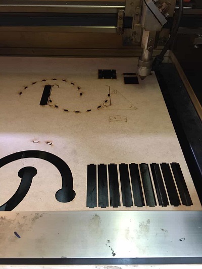
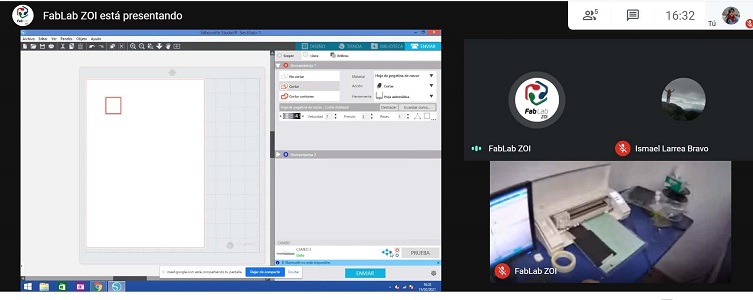
Once we had the kerf for this material we started cutting out pieces,
when they were ready we put all of them together. This was the result:
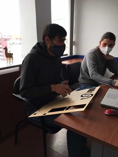
Camilo, Ismael and I worked on this on the lab and Jeffery worked remotely.
Fortunately the lab has a camera located in the laser room and all of us could
see what the other was doing in the meeting room and also in our computer screens
while connected to google meets.
PARAMETRIC DESIGN
Parametric design is a process based on algorithmic thinking that enables
the expression of parameters and rules that, together, define, encode and
clarify the relationship between design intent and design response.
Is a paradigm in design where the relationship between elements is used
to manipulate and inform the design of complex geometries and structures.
The term parametric originates from mathematics (parametric equation) and
refers to the use of certain parameters or variables that can be edited
to manipulate or alter the end result of an equation or system. While
today the term is used in reference to computational design systems,
there are precedents for these modern systems in the works of architects
such as Antoni Gaudí, who used analog models to explore design space.
PREPARING THE FILE
For this task the pieces to be cut with laser technology must be parametric.
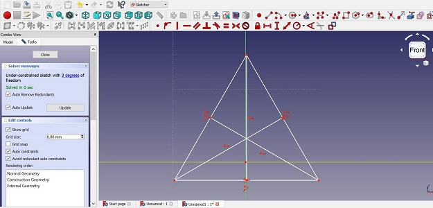
This week I decided to try freecad again as it offers easy parameterization
options. However, it was not an easy task, I am still learning to use the
program.
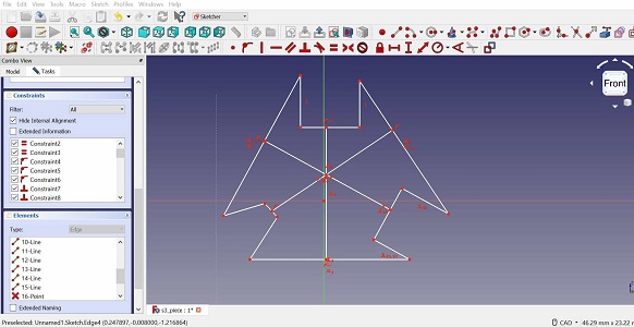
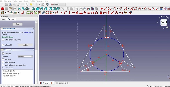
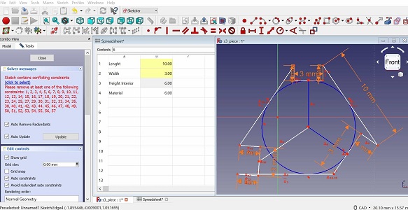
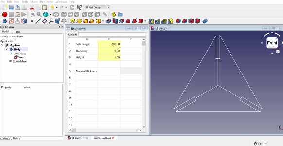
First I drew the piece for my exercise, not so complicated till this point.
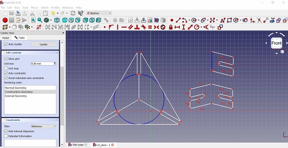
Then, I tried to parametrize it adding data, it seemed to work but not in all
sides of the piece as I expected. Added a new piece to the design, and still had
the same troubles.
I didn't get the expected result but I won't give up and continue trying with freeCAD in further exercises.
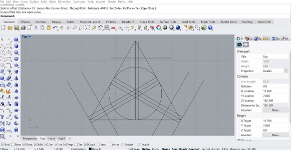
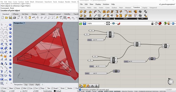
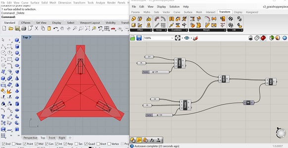
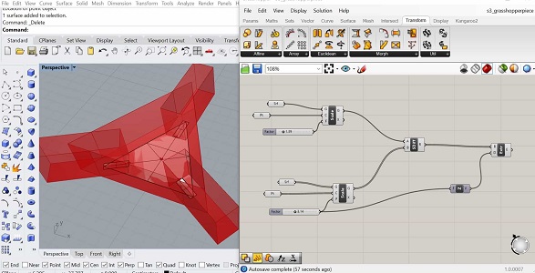
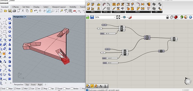
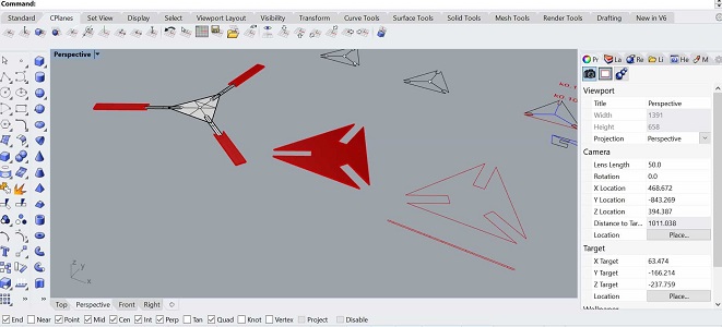
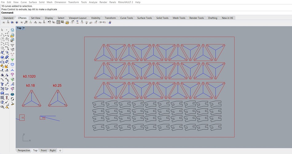
So, I ratter made my design in Rhino and grasshopper which I know a bit better.
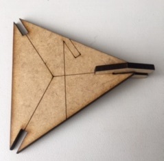
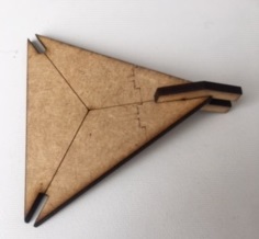
Drew the same shape and added three parameters that can be modified:
size of the triangle, widht of the vertex slice and width of the material
which are both linked, one will affect the other. Then extruded and subtracted.
Once baked I can delet the unneeded pieces and turn in to 2D for the laser cut.
FILES
FreeCAD file.
Rhino file.
Grasshopper file.
Rhino and Grasshopper files with some updates.
SETTING THE LASER CUTTER
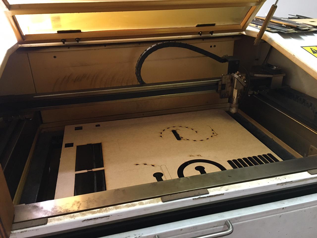
For this exercise we used a laser machined "made in Ecuador and hacked by ZOI"
as my instructur said. It works for a 60x40cm format.
With my design ready and modified I had to do another test because
we changed the material to a 4mm plywood. This was the result, parameters
and comments can be found in table below:
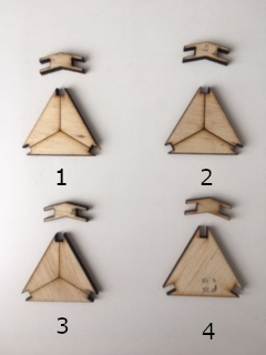
| TRY |
MIN POWER (%) |
MAX POWER (%) |
SPEED (mm/s) |
PARAMETERS USED TO ENGRAVE |
COMMENTS |
| 1 |
65 |
65 |
6 |
Min:20 Max:20 Speed:70 |
It is burning the piece and the tips are chipped
Lines aren't clear enough |
| 2 |
55 |
55 |
6 |
Min:30 Max:30 Speed:70 |
Borders are comming up black and burned.Still chipping the tips.
Lines too dark, the wood looks burned |
| 3 |
45 |
45 |
6 |
Min:25 Max:25 Speed:70 |
Looking better but still black borders.
Perfect color and depht of lines engraved |
| 4 |
35 |
35 |
15 |
Min: Max: Speed:No engraving |
This is the result expected, not burning the drew lines,
clean cut, not chipped tips.
|
WORKFLOW FOR THE LASER
For this exercise and the following parameters I used a 1.5mm cardboard.
- Turn on the machine, make sure the chiller and air pump are on too.
- Make sure there is no residue from previous cuts on the machine, which could cause fire or an accident
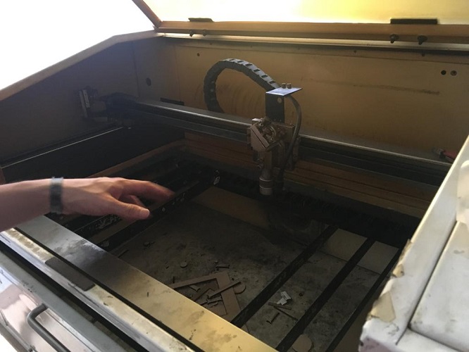
- Load the material in the work area, add some tape to secure it if needed
- Focus the laser on the material, use the 'focus meter' (a laser-cut piece that has the right dimensions 22x22mm) to set the correct hight above the material surface
- Move the lens to the desired starting position and set the origin
- Level the laser cut using a piece on top of the material and adjusting the top of the laser nozzle.
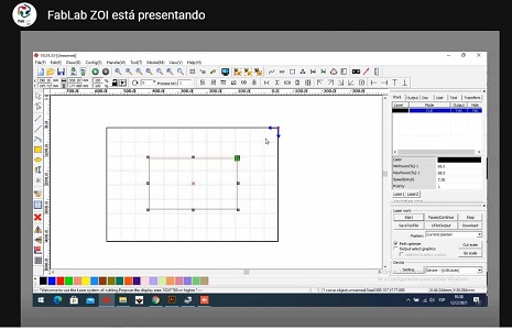
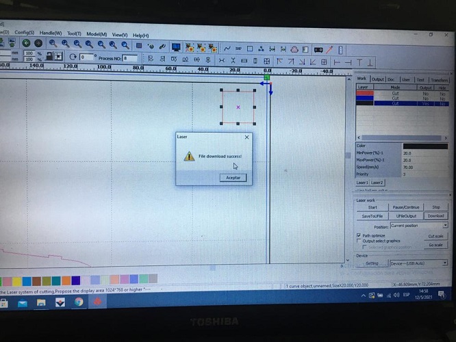
- The software used for the laser is RD Works
- File >import > .dxf file
- The green square on the corner show the origin for the laser
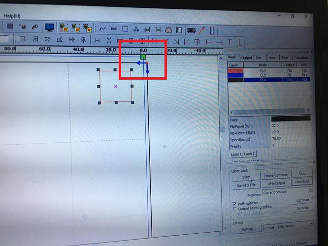
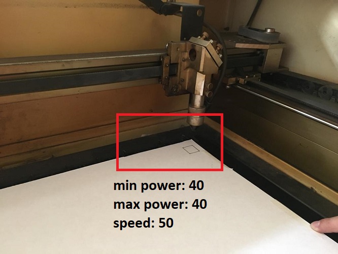
- To make sure about the power and speed are the right ones for the work, and the material, it is recommended to draw an small square and try the parameters
- This square size is 20x20 mm
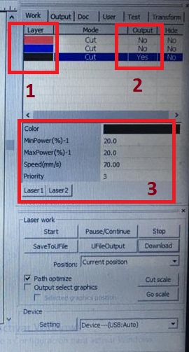
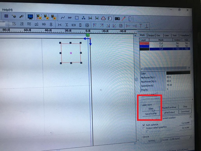
- Make sure of 3 important factors:
- The color of the layer, according to this you can set different parameters to cut or engrave. You can also change the order of this layers in the order you want the machine to work, for example firs engraving, second cutting (on priority).
- The output shows if you want to cut it or not.
- Set the parameters: min and max power, speed, and priority (the order of the layers)
- For this exercise, I tried:
- Min power:20
- Max power:20
- Speed:70
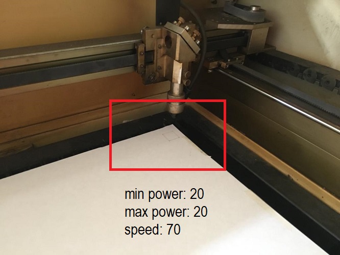
The result wasn't the one expected, the laser wasn't cutting, so I tryed this parameters:
- Min power:40
- Max power:40
- Speed:50
- Once the parameters are ready you can click on start to send the square to the laser
- You can also, pause or stop during the cut if needed.
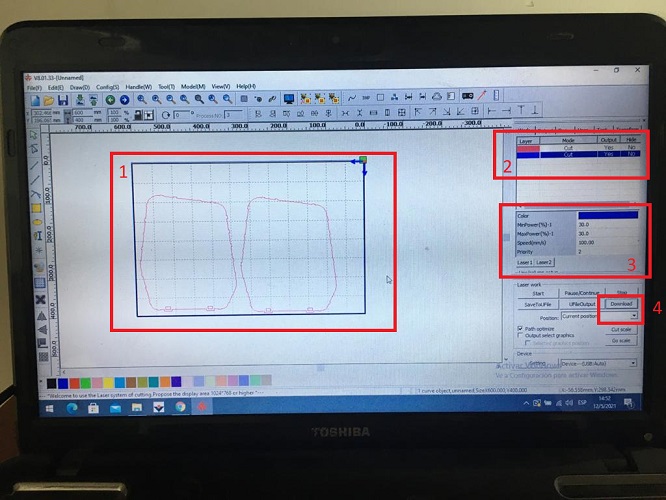
- Once the test is done, follow the next steps:
- Make sure all the drawing is inside the limits
- Make sure the layer (color and order), output (yes or no, depending on what you need) and order is right
- Make sure the parameters are correct, min power, max power and speed
- Press download to send the file from the computer to the laser machine
- Write down a name for the file
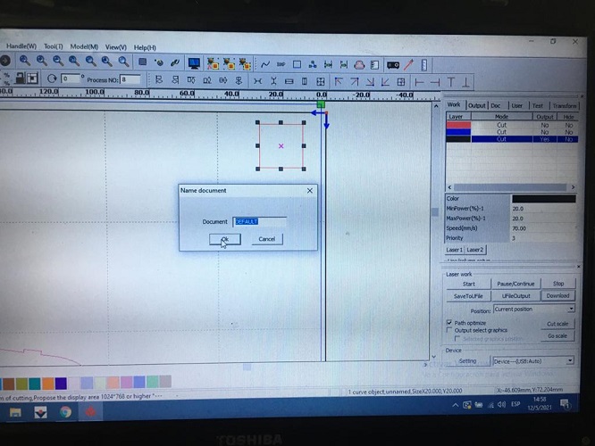
- When it is ready this message will come up
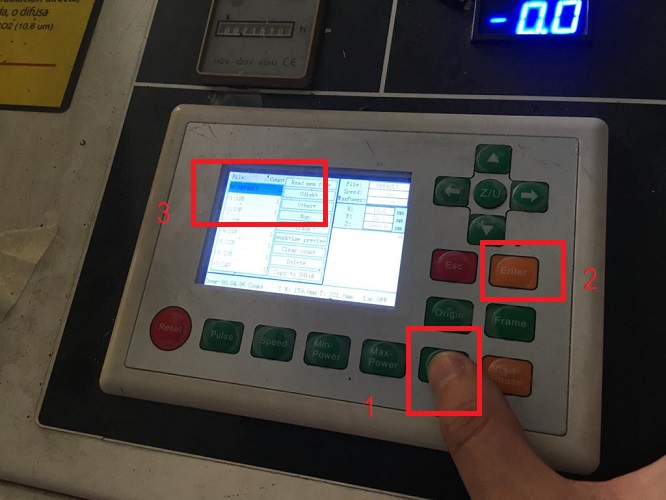
- On the machine, follow the next steps
- File
- Enter
- Look up for the file saved > Enter
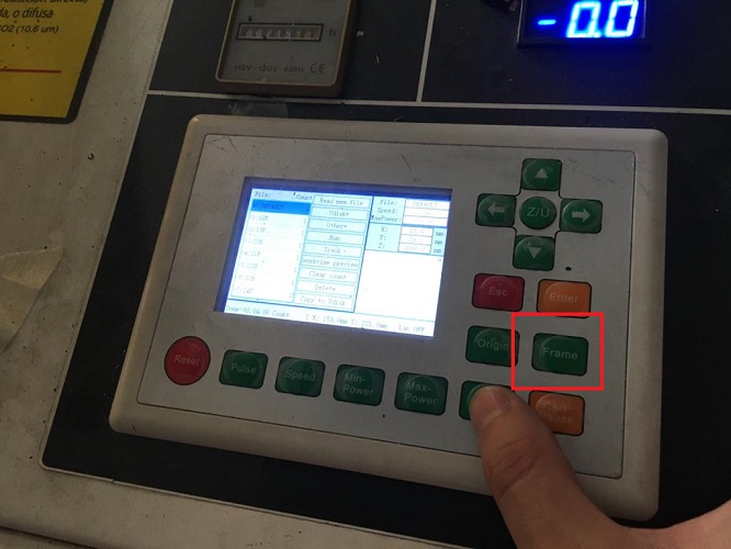
- Press frame to check that the file is within limits of the machine. In case it isn't a message will come up and the frame test wont execute.
In this case you should first check the file limits, or check the origin set on the machine.
To set the origin on the machine, you can move with the arrows and press origin.
- Start (this same button can be used to pause
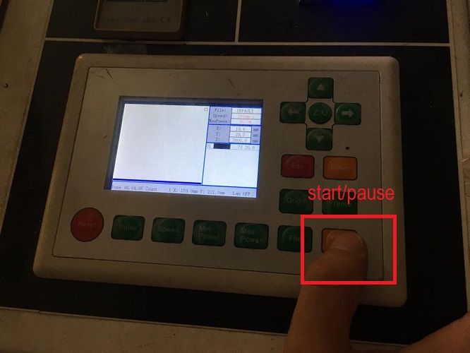
- Remove your pieces from the machine. In case the pieces felt
on the base of the machine, open the front lid and take them out.
MATERIALS AND PARAMETERS TESTED
| MATERIAL |
THICKNESS |
MIN POWER (%) |
MAX POWER (%) |
SPEED (mm/s) |
COMMENTS |
| plywood |
plywood |
35 |
35 |
15 |
CUT |
| plywood |
4mm |
25 |
25 |
70 |
ENGRAVE |
| cardboard |
1.5mm |
40 |
40 |
40 |
CUT |
| cardboard |
1.5mm |
25 |
25 |
70 |
ENGRAVE |
| mdf |
4mm |
75 |
75 |
8 |
CUT |
NESTING
To make the most out of the material I made a random nesting by hand, trying to place the pieces as close as possible without compromissing the pieces.
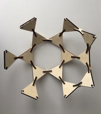
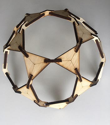
FINAL RESULT - MY CONSTRUCTION KIT
The task looks for a design which is parametric, more than a finger joint
box and that you can assemble in multiple ways. I choose triangles as they
allow many posibilities. Here some of the things I tried:
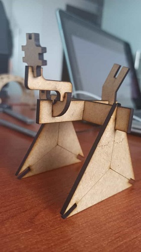
Started with something logic and ordered (need some extra pieces, when I
designed it I wasn't thinking about an specific result so I didn't quantify
the pieces, but with this result I now know what I can achieve).
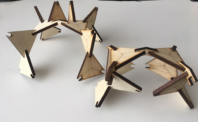
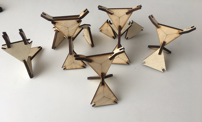
Then I tried mixing pieces and assembles, the result was really interesting,
I had a lot of fun putting together my pieces.As result here you can look at some cows and robots.
Vinyl cut
Preparig the files
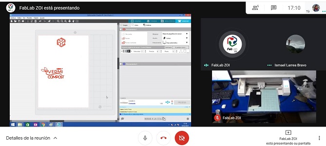
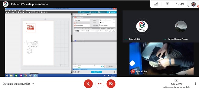
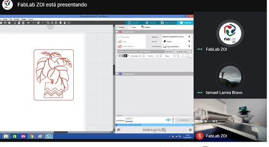
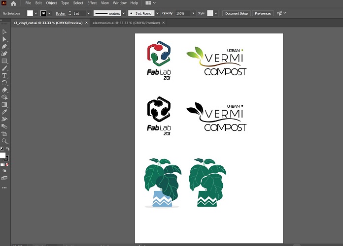
It is important to have a vector drawing for this activity, to do that I used illustrator. I started redrawing our labs logo from a picture I downloaded
from the internet, used image trace to generate the contour but the resolution of the image was pretty bad so I better draw it myself using the pen tool.
I also desing the logo I want to use for my final project, to do this I also used the pen tool for the leaves, added some colour in gradient.
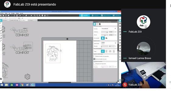
And finally edited a vector shape, in this case a plant wich I also plan to use for my final project.
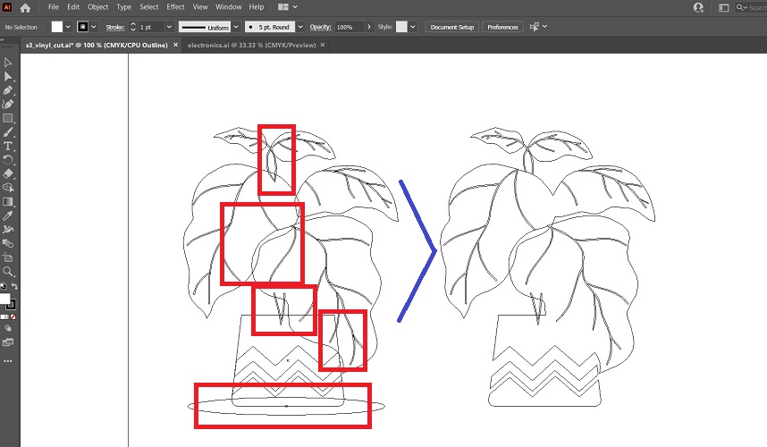
To use the vinyl cutter it is necesary to have a plain color for the contour, make sure there are no lines on top of eachother.
We cut our pieces remotly with the lab, sent our files in .dxf format and
Camilo helped us setting the material on the machine and remove unwanted material.
The first try was a logo I designed for my final project, but the lines where too thin,
so it became a nightmare for Camilo.
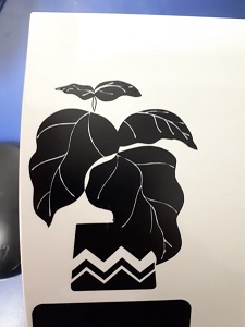
I sent another file which I modified from a
previously downloaded vector of a plant. This one turned out as expected.
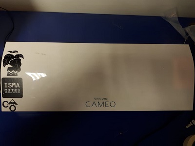
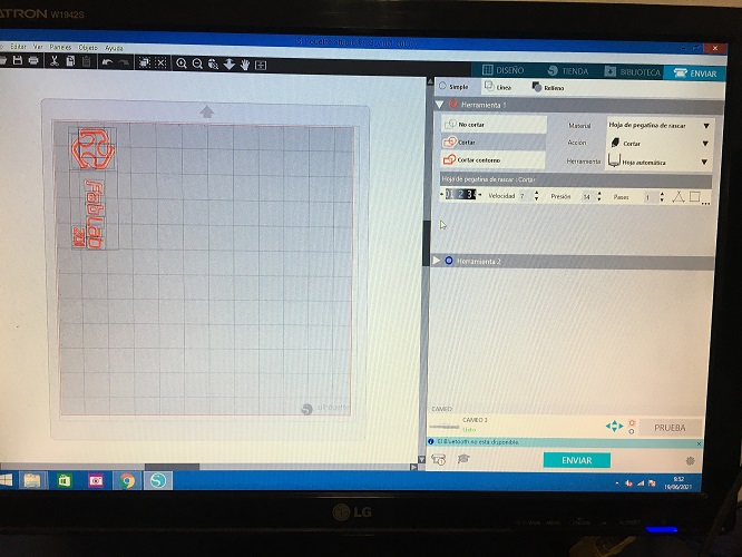
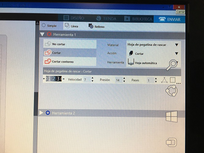
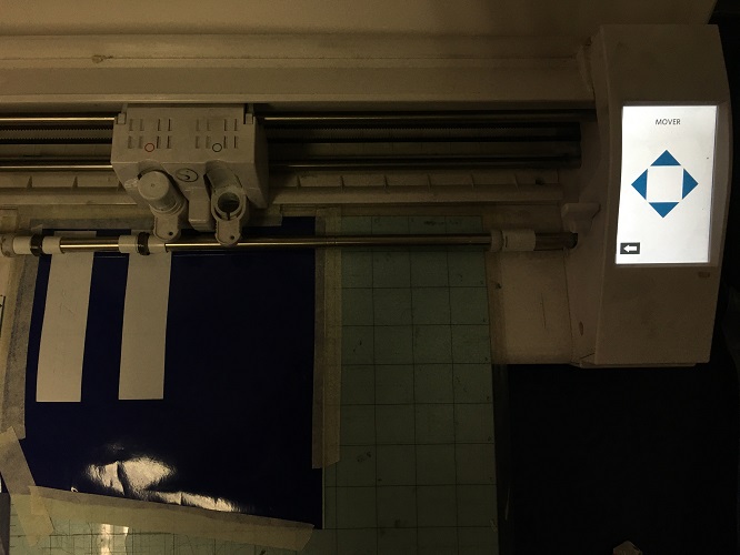
The machine we used is a Cameo, with the following configuration:
cuchilla (blade): #3
velocidad (speed): 6
presion (pressure):3
pases (passes):1
FILES
Illustrator file.
CAMEO WORKFLOW
Vinyl cut is pretty simple, this are the steps to follow:
- You need your file in .dxf
- Open the program, go ti File> open> and select file
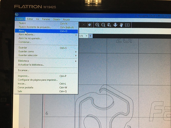
- Place the drawing in the origin and set the parameters
- In the cutter, press "Cargar" (load) to set the material.
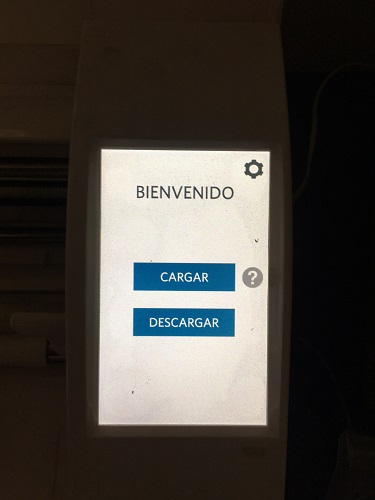
- You can move with the arrows to set the origin in the machine (in this case this is necessary to do since I am going to use just one side of the vinyl sheet, the other one has been used already)
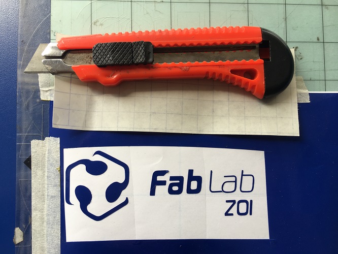
- Send the file. Press remove in the cameo and take out your vinyl sheet. Remove the unneeded parts using a knife
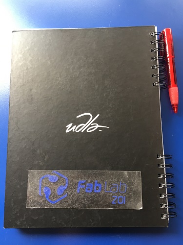
- To transfer the vynil you have to place a transparent kind of vinyl on top, it is actually called transfer, and remove your design.
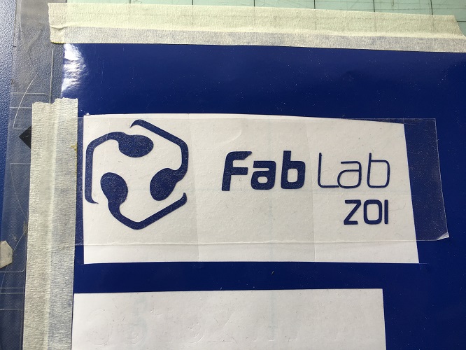
- Paste it where you need it and remove the transfer sheet.
FINAL THOUGHTS ABOUT THIS WEEK
Testing and learning about this technology has opened up endless possibilities
for my designs. One of the main reasons why I took the Fab Academy was to
explore new alternatives for furniture design and construction, I
am happy with the path that I am going through.
Just to remember, now I'm using this site for image compression, found it easy to use.
Optimizilla
I'm also having trouble uploading my design files because they are too heavy.
All the infomration needed for git large file storage is avaliable in these links:
Download Git Large File Storage
Git Hub Docs
Step by step in youtube
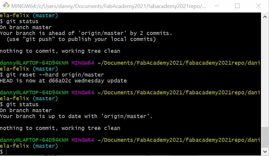
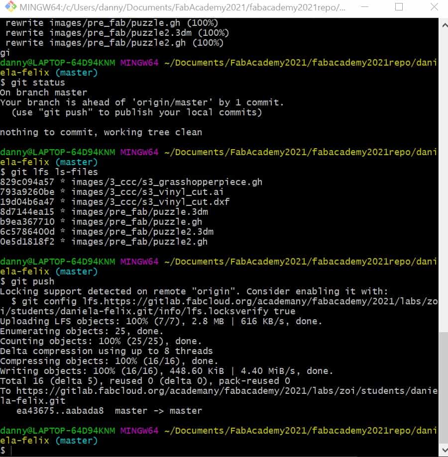
Im crossing my fingers, hope it works today.