INTERFACE AND APPLICATION PROGRAMMING
When you use an application on your mobile phone, the application connects to the Internet and sends data to a server.
The server then retrieves that data, interprets it, performs the necessary actions and sends it back to your phone.
The application then interprets that data and presents you with the information you wanted in a readable way.
GROUP ASSIGNMENT
Find out the details of our common work al ZOI
Here.
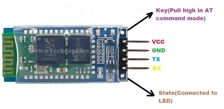
BLUETOOTH HC-06
This bluetooth is a "secondary" device that has serial communication and power pins. Here you can find the data sheet for further information.
Also it is important to be aware of the pins out:
- VCC: connect to 3.3V of the microcontroller
- GND: connect to ground
- TXD: connect to RXD pin of the microcontroller to transmit serial data (wireless signals received by the bluetooth module are converted by module and transmitted out serially on this pin)
- RXD: connect to TXD pin of the microcontroller. The bluetooth module receives the data from this pin and then transmits it wirelessley
HC-06 Data sheet.
SETTING UP THE HC-06
Before using this module it is necessary to set it up. We used arduino IDE to do this. This are the steps to follow:
- Open Arduino IDE and the serial monitor
- *Make sure at the bottom of the screen you have: - no line ending, -9600bauds,
- Write down AT+PIN (to set a password)
- Example: 1234
- Write down AT+BAUD (to determine the speed of communication over a data channel)
- Example: 9600 (which is the most common and it is also found in the data sheet
- Write down AT+NAME (to assign a name you can found as bluetooth device(
- Example: ZOIFABLAB (max 20 characters with no special characters)
Then, follow the next steps:
- Connect the arduino and upload the code without connecting the bluetooth
- Disconnect the arduino y connect:
- ARDUINO - BLUETOOTH
- 0 - TX bluetooth
- 1 - RX bluetooth
- GNG - GND
- VCC - VCC
- Connect the Arduino and wait for a couple of minutes for the configuration to ulpoad
- Disconnect the Arduino to let the name and password to refresh
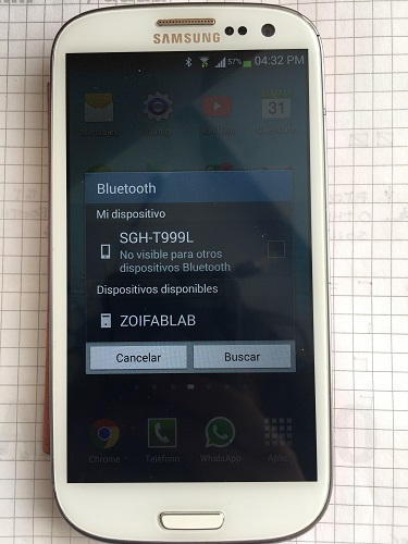
- Verify that the name has changed, checking on the phone for bluetooth avaliable networks
You can find the code for Arduino to configure the HC-06 Here.
*BAUD:In telecommunication and electronics, baud (/bɔːd/; symbol: Bd) is a common unit of measurement of symbol rate, which is one of the components that determine the speed of communication over a data channel.
UPLOAD THE CODE TO THE BOARD
I have a RBG led planned on my board, so I could connect the bluetooth module to it. To do this is necesarry to know the pins im going to use first
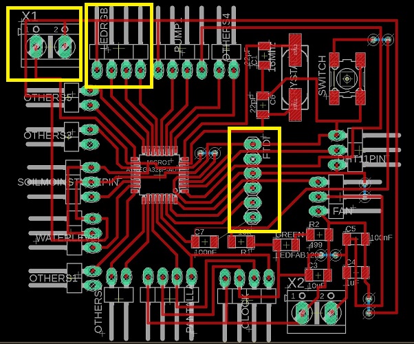
- BOARD TO RGB LED
- Pin 13 = D9 (red)
- Pin 14 = D10 (greeen)
- Pin 15 = D11 (blue)
- Pin 16 = GND
- PROGRAMMER TO FTDI ON BOARD
- GND - GND
- No connection on second pin
- VCC - VCC
- RX - TX
- TX - RX
- RST - RST
- Upload the code. You can use the example provided by the App inventor community avaliable on this
link
or the one we modified according to what we needed for the app, avaliable here:
#define PinR  11
#define PinG  10
#define PinB  9
char caracter;

void setup() {
    Serial.begin(9600);
    pinMode(PinR, OUTPUT);
    pinMode(PinG, OUTPUT);
    pinMode(PinB, OUTPUT);
    analogWrite(PinR, 0);
    analogWrite(PinG, 255);
    digitalWrite(PinB, LOW);
}

void loop() {
    if (Serial.available()) {
    caracter = Serial.read();

    if (caracter == 'a')
    { analogWrite(PinR, 255);
        analogWrite(PinG, 255);
        digitalWrite(PinB, HIGH);
    }
    if (caracter == 'b')
    { analogWrite(PinR, 0);
        analogWrite(PinG, 255);
        digitalWrite(PinB, HIGH);
    }
    if (caracter == 'c')
    { analogWrite(PinR, 255);
        analogWrite(PinG, 0);
        digitalWrite(PinB, HIGH);
    }
    if (caracter == 'd')
    { analogWrite(PinR, 0);
        analogWrite(PinG, 0);
        digitalWrite(PinB, LOW);
    }
    }
}
You can download the Arduino File
Here
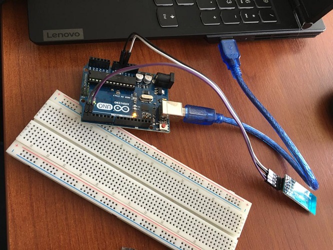
Here you can see a picture of this first connection.
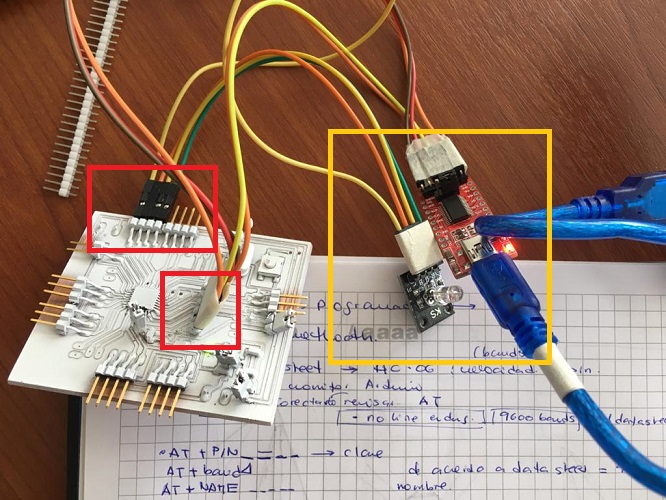
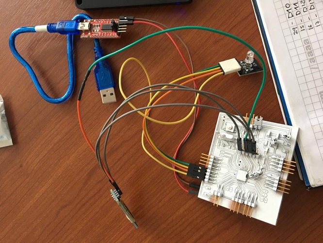
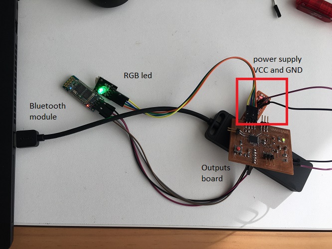
CONNECT THE BLUETOOTH MODULE TO THE BOARD
Using the FTDI pins connect the bluetooth module:
- GND - GND
- No connection on second pin
- VCC - VCC
- RX - TX
- TX - RX
- RST - RST
APP INVENTOR
Go to APP INVENTOR
and click on create apps. Create an account and access to the platform. Follow the next steps:
- Projects > Import project (.aia) from my computer
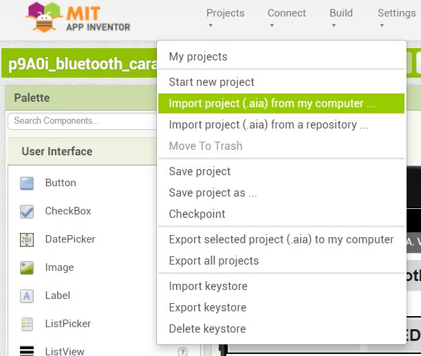
- Load the .aia file avaliable on the next link "On - off LEDS"
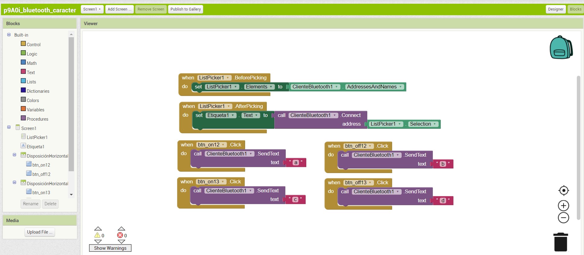
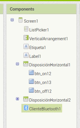
- Here you will find four blocks previously configured:
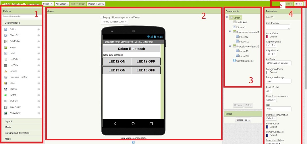
- Pallet: where you can find many options for your interface
- Viewer: shows a preview
- Components: shows the components selected and active in the app
- Properties: allows to change the configuration of the components
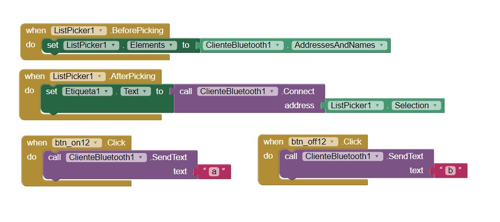
- Blocks: opens the code to run this app. You can go back to design by clicking on design located on the top right side of the window
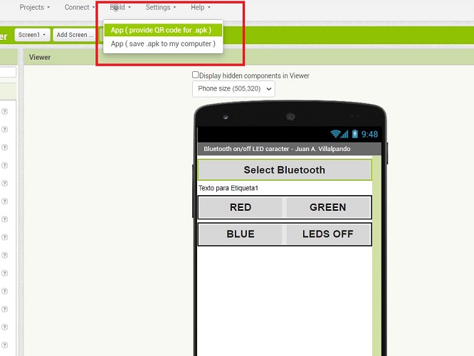
- Now that everything is set, go to build> App > provide QR code.
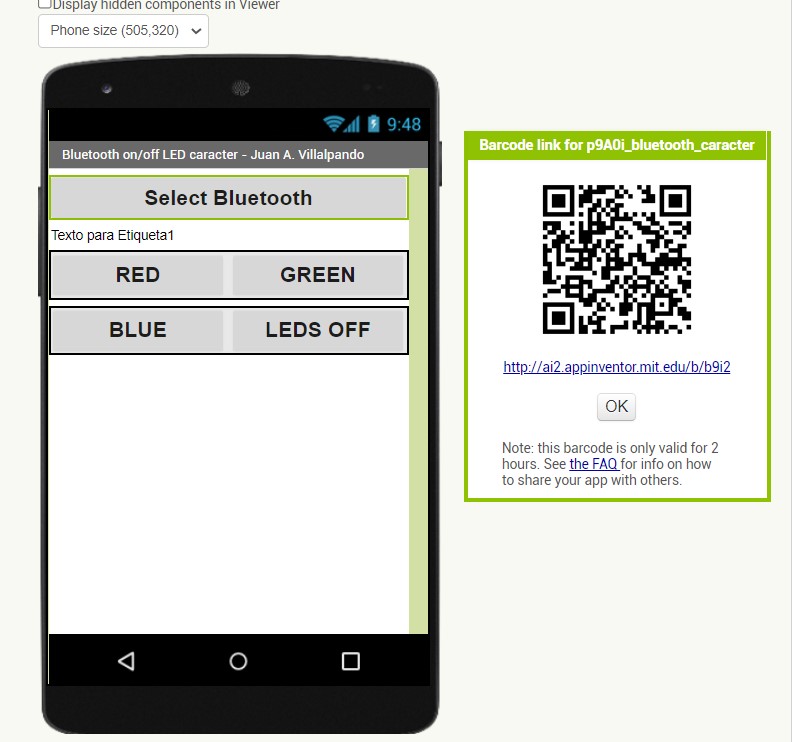
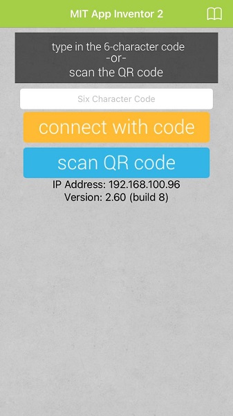
- Open the MIT APP INVENTOR on you cell phone
The following video the result 😊
File
Here you can download the .apk file of this app to try it yourself.
Also, the Arduino file
Trying another app on my own
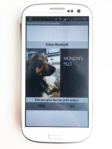
Based on the previous exercise and looking to generate a useful application for the day to day, I have designed a reminder about my pet's pills.
Monchis is a 6-year-old dog with hypothyroidism who takes pills every day. Sometimes I feed her and other times Alvaro, my boyfriend. But we are constantly
asking each other if she has already taken her pills or not. With this indicator we can let the other know the status of Monchis.
The idea is that if she has already eaten and we gave her her pills, we put YES in the application and the Led will turn green, if we didn't have time or there are no pills,
we should put NO and the led will turn red.
In the outputs week I tried a simple program to turn on the RGB led, which worked as a guide for this exercise. Also, based on the programming of the
previous exercise this week, I integrated two characters: a and b to associate them with the LEDs in the application.
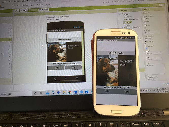
In App inventor I integrated some new elements to change the user interface of this application. I integrated text, changed colors, added a photo of Monchis and this was the result.
In APP Inventor I used three blocks: the first to place the bluetooth label, the cover image that creates it in Photoshop, a label that is not visible and that determines
true or false for the bluetooth status, the text for the pills questions. The second, with the YES and NO buttons that are associated with the LEDs. Third the bluetooth.
For the blocks I used character a and b to be recognized trough the bluetooth, after picking it on the list. If the user picks "a" this means NO and the red led will turn on.
If the user picks "b" this means YES and the green led will turn on.
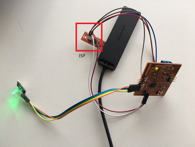
Next step is to programm the board to control the led. In this case I used my outputs board and my ISP programmer and Arduino IDE. To upload the code I used MOSI, SCK, RST, MISO, VCC, GND. Later, to connect the bluetooth
module I had to disconnect the ISP and connect it trough the FTDI. To power the board I still used my programmer but just to VCC and GND.
To try the app follow the next steps:
- Select bluetooth. In this case ZOIFABLAB
- The password is 9876
- Scann the QRT code provided by App inventor
- Download the app
- This cell phone required a security permission to install outside of Google Play apps
- Run the app
This is the final result:
TROUBLESHOOTING
This seemed like an easy exercise, but I found some problems to solve that appeared with the first tests in the app.
- The first time I tried the app, the image was elongated, so I decided to change its proportion in the application (although it looks distorted, when viewing it on the cell phone it is correct)
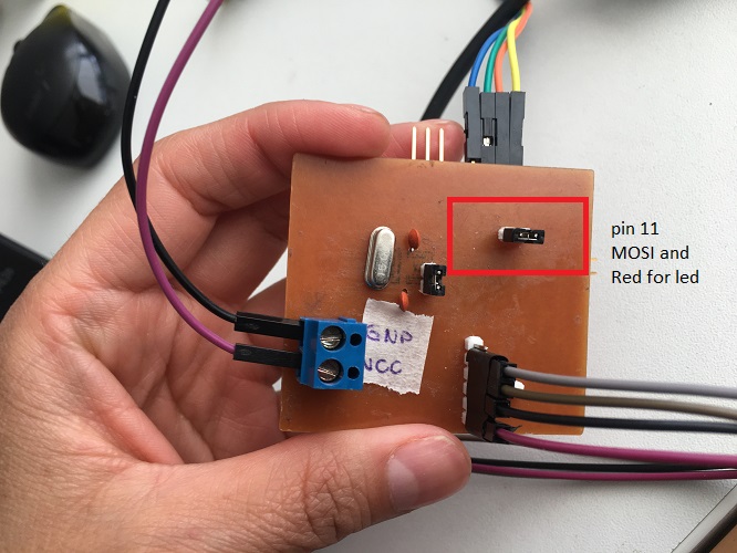
- The led uses the same chip as MISO (pin 11), so in the design of the board I used a jumper. At the beginning, the LED only showed green even though all
the wires were already connected. I was forgetting to connect the bridge, once I did it showed other colors (not the red I was expecting, but at
least other colors). I had to change the programming.
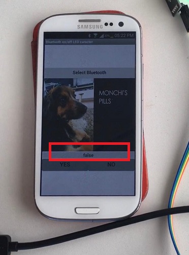
- When starting the application the text of "Did you give her her pills today?" It appeared well, but when selecting the bluetooth it disappeared and it
only showed true or false depending on the connection. For this I added a new block in the App only with the initial question and the
bluetooth connection block was left non visible.
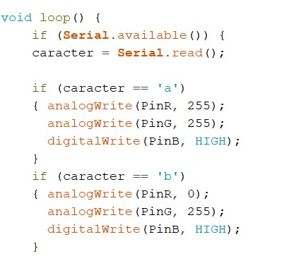
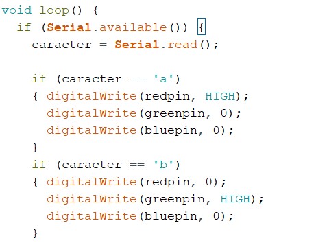
- In the code these are the values I had at the begining and the ones I tryed. I changed the variables names, changed them all to digital write and changed the values (had the combined with numbers and HIGH and LOW).
Once again, lots of colors but no red and green plain.
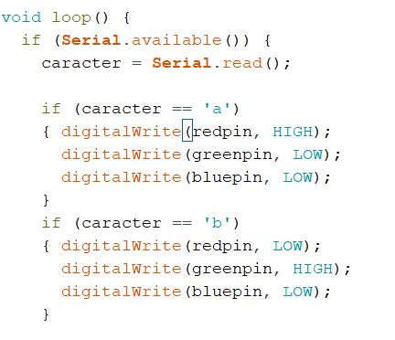
- Change the code again, now just to HIGH and LOW.Now it works.
files
Arduino file
.apk file
comments
Even though I have a hard time programming, I enjoy this activity, it is a bit tedious to connect and reconnect with each attempt, but the result is
interesting. I like the process of creating the user interface and giving it interaction possibilities. Little by little I will improve with the
programming, at the moment it is easier to understand an already created code and make small adaptations, create a code from scratch ... we'll see.
SOME TOUGHTS ABOUT THIS WEEK
I found this week very interesting to be able to create an application. On a day-to-day basis it seems to have become so essential and easy to
use an application for almost everything, but I could see that it takes a lot of work to achieve an attractive interface. Little by little I
understand all these processes better, with a very logical mind, which follows step-by-step instructions (something I'm not usually used to).
However, the code generation is still the most complicated part for me. So far, I understand part of the language, but I do not know the commands
necessary to create a new one. For now I will base my work on examples available online, adapt, modify and apply them to my work.