Week
Three
CNC cutting
Group Project
The group project that we set to work on was creating a project that we can use to test various different settings on the laser cutter. Now us being basic sort of folks we felt that we didn't need to come up with something insane to cut out. So we went about in the way we felt was simplest that being we just made a square. Now would I love to show you a photo of these squares? yes I would. Do I have these squares? Yes I do, however I don't have them here with me as I write up this assignment, so I will share a photo of the squares, and the board we cut them out of. However I think that you can visualize this square, it is a square that has a side length of 2 cm cut out of cardboard. Now when we were cutting these out we varied the settings in order to see how that would affect the results of the cuts. So I'll tell you a little about each settings.
Power
Power does what it says on the tin. It controls the power of the laser. We can see that when the power is to low, our material isn't cut through, and when it is too high it leaves burn marks on the material that we are cutting. So to optimize cutting we want it high enough so that it cuts through, but not so high that we have a material covered in ash.
Speed
The speed setting changes how quickly the laser moves about while cutting. We saw that when the speed setting is really high then we end up with a situation where the laser won't cut through. We didn't cut at to slow a speed because I've been told in the past that should the laser be moving too slowly then the trailing fire behind the laser can spark a much larger fire, and then we'd have issues on our hands.
Frequency
Frequency from what I gather is the amount of time that the laser is on when things are being cut. Meaning that should the frequency be set at 50 and the power at 100 then that is the same as the power is at 50. From what we could tell in our testing we didn't see any differences when changing frequency with the exception of if it is too low it won't cut. I don't know if there are any funky situations that can occur and cause really interesting cuts, but I wasn't able to see it.
Kerf
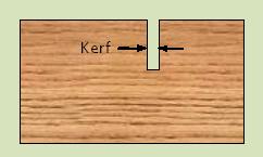
Kerf is the term used to describe the width of the laser. This was the main thing that we needed to use these experiments to figure out. So when we did each cut we measured to see how much it differed from the 2cm we had it set to. We found after our tests that there was about a half milimeter difference, with that being on both sides, we can divide the by two, and see thtat the kerf should be about a quarter of a milimeter.
Focus
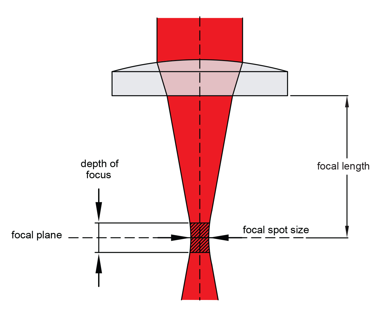
Focus in regards to a laser cutter is making sure that your cutting material is in the right position so that it is in your lasers focal point, and it actually giving the most power, at the smallest point. When we did tests to see how this was going to affect our cuts we had interesting results. Those being that we had almost no change. We did two tests one where the laser is further away from where it ought to be, and another where the material was nearly right next to the laser. In both instances we didn't see a shocking amount of difference. When I talked to a professor about this he said that we had the laser set up with a large depth of focus to make it less likely that the users would mess something up.
Type
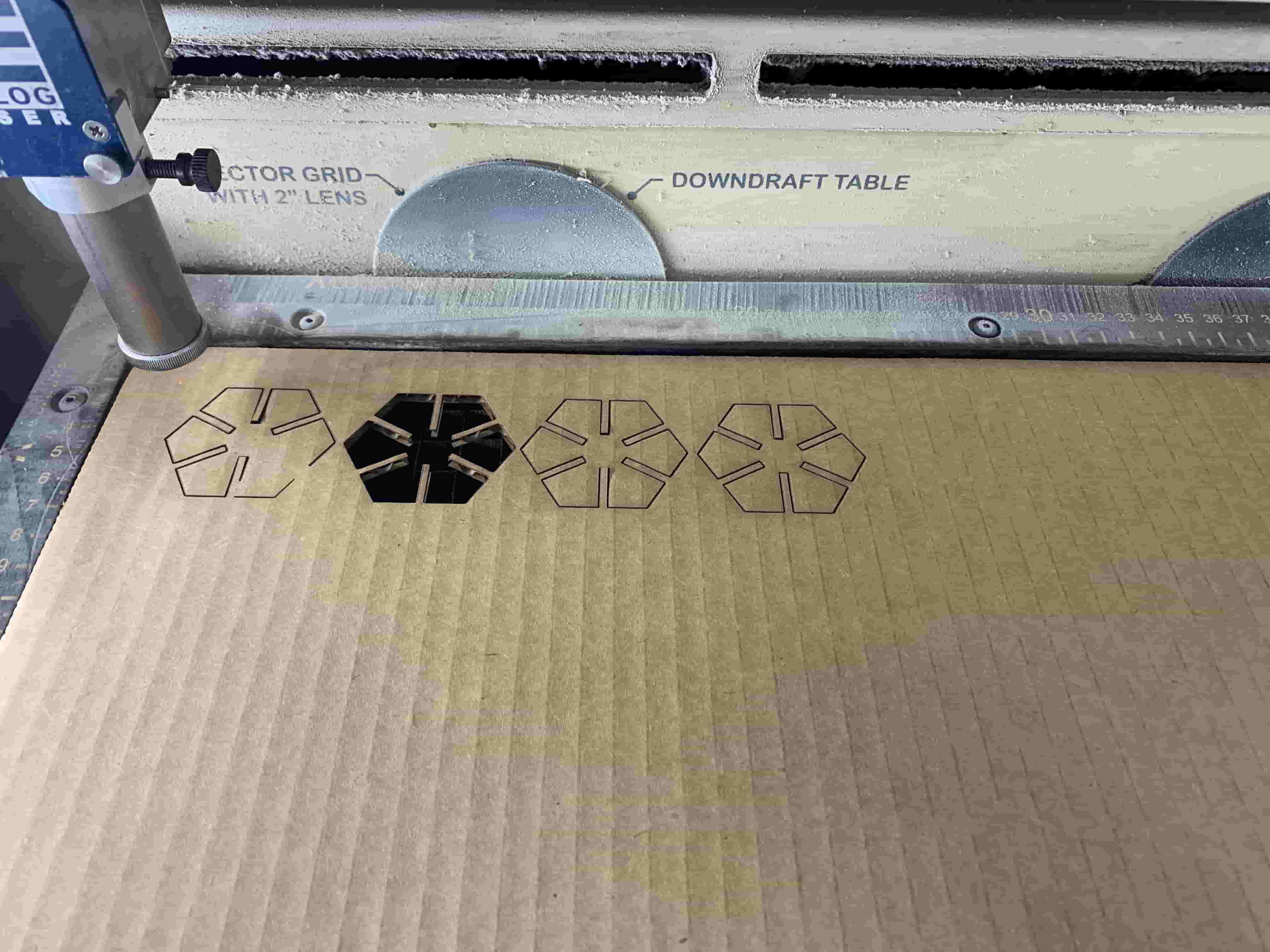
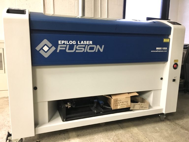
Type. I'm not sure exactly what folks meant by type, my group also didn't know what you meant by type. The way I see it you could be talking about two different things. One being the type of laser cutter in which case it is a Epilog Fusion M2 40 laser.
If you are talking about the type of material then that is kinda dependent on the sort of material. Thinner things need less power well unless they are denser materials.
Joint Clearance
I'm not sure what joint clearance means, but I suspect that it has to due with making sure that the design that I laser cut has the proper space to make it so the things I want to interlock actually interlock.
Vinyl Cutting
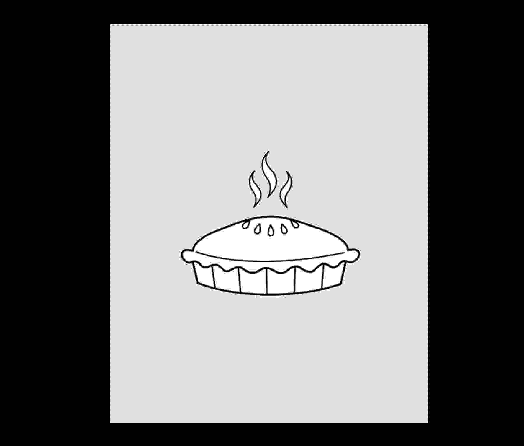
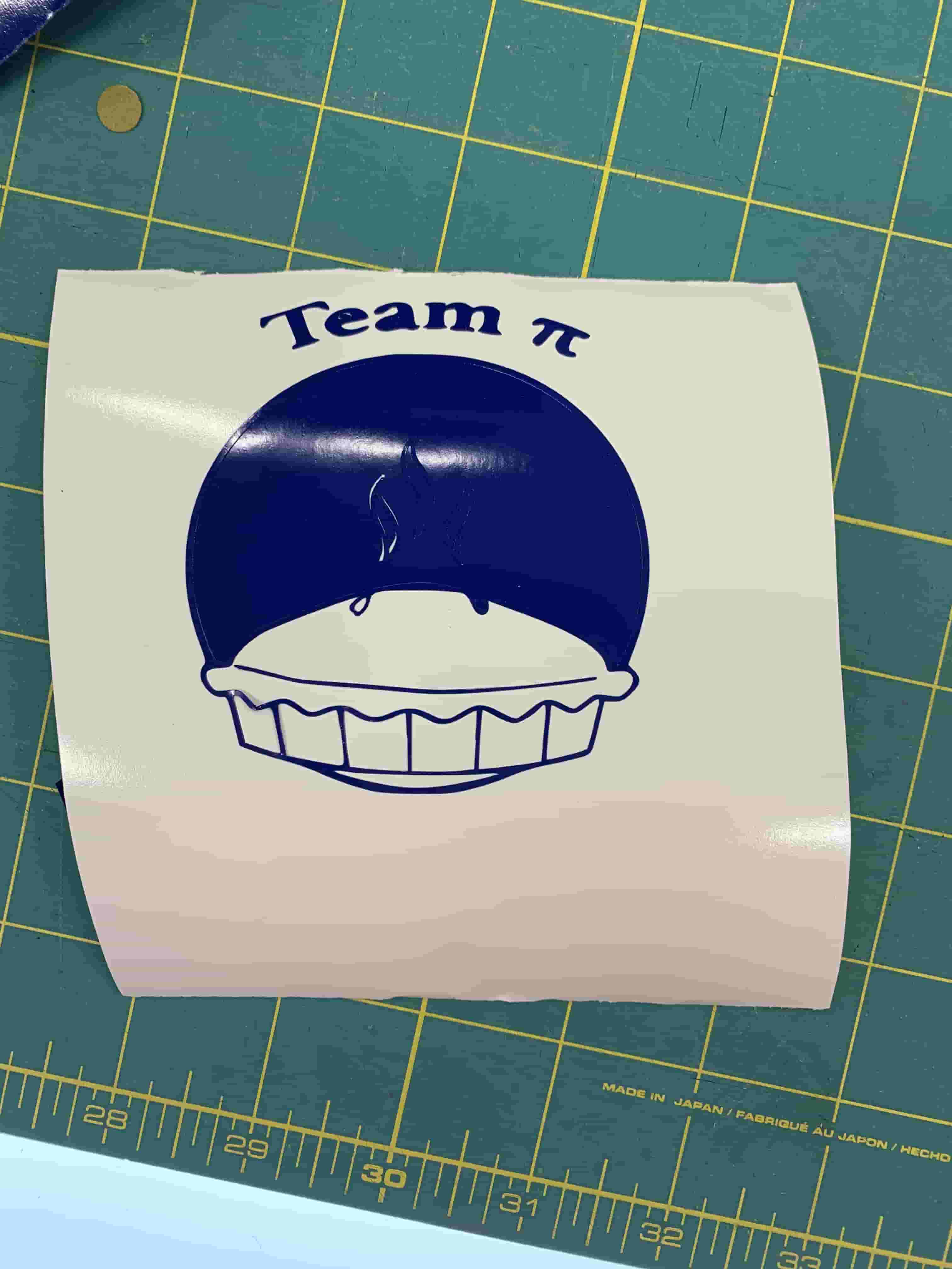
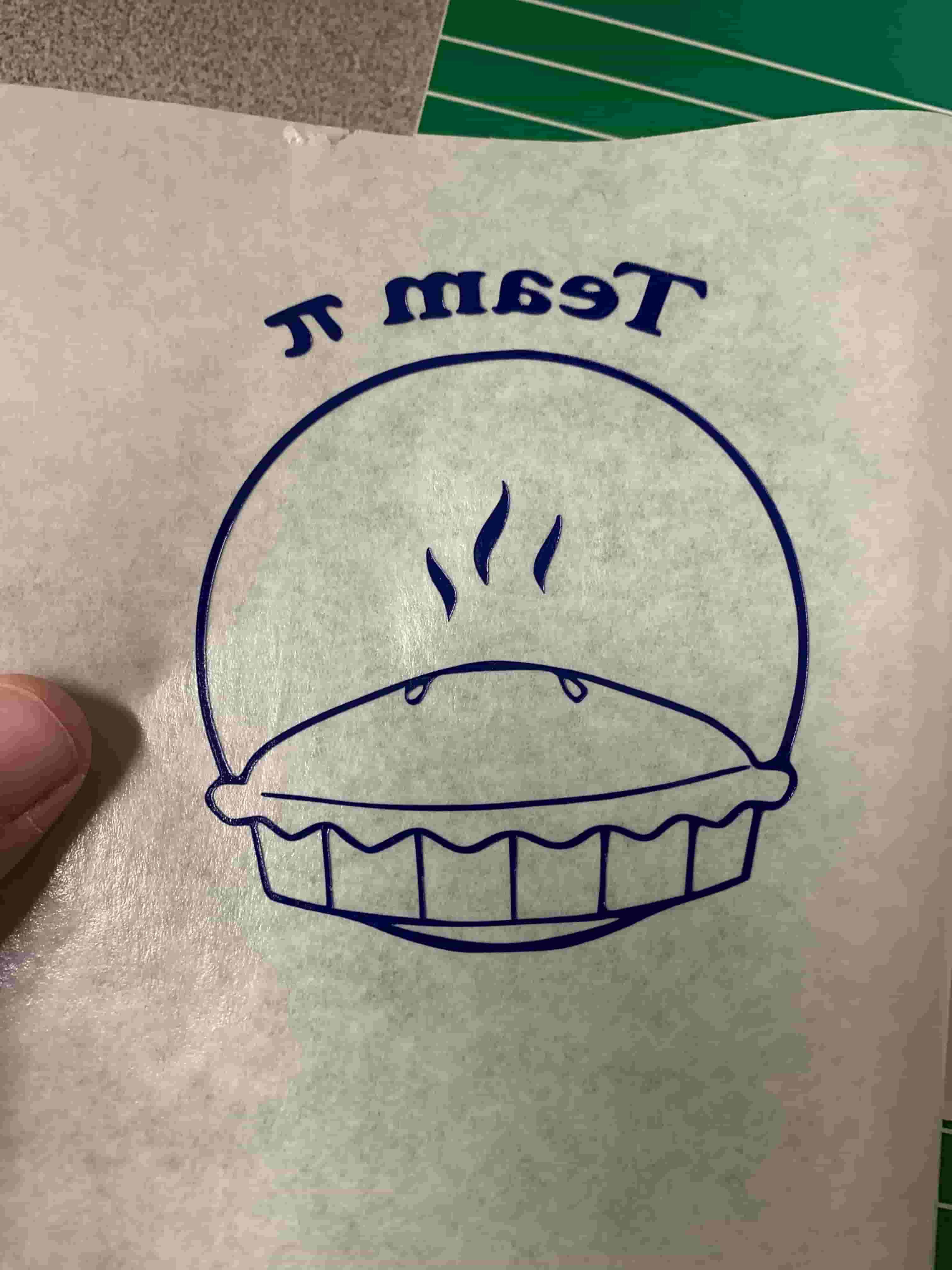
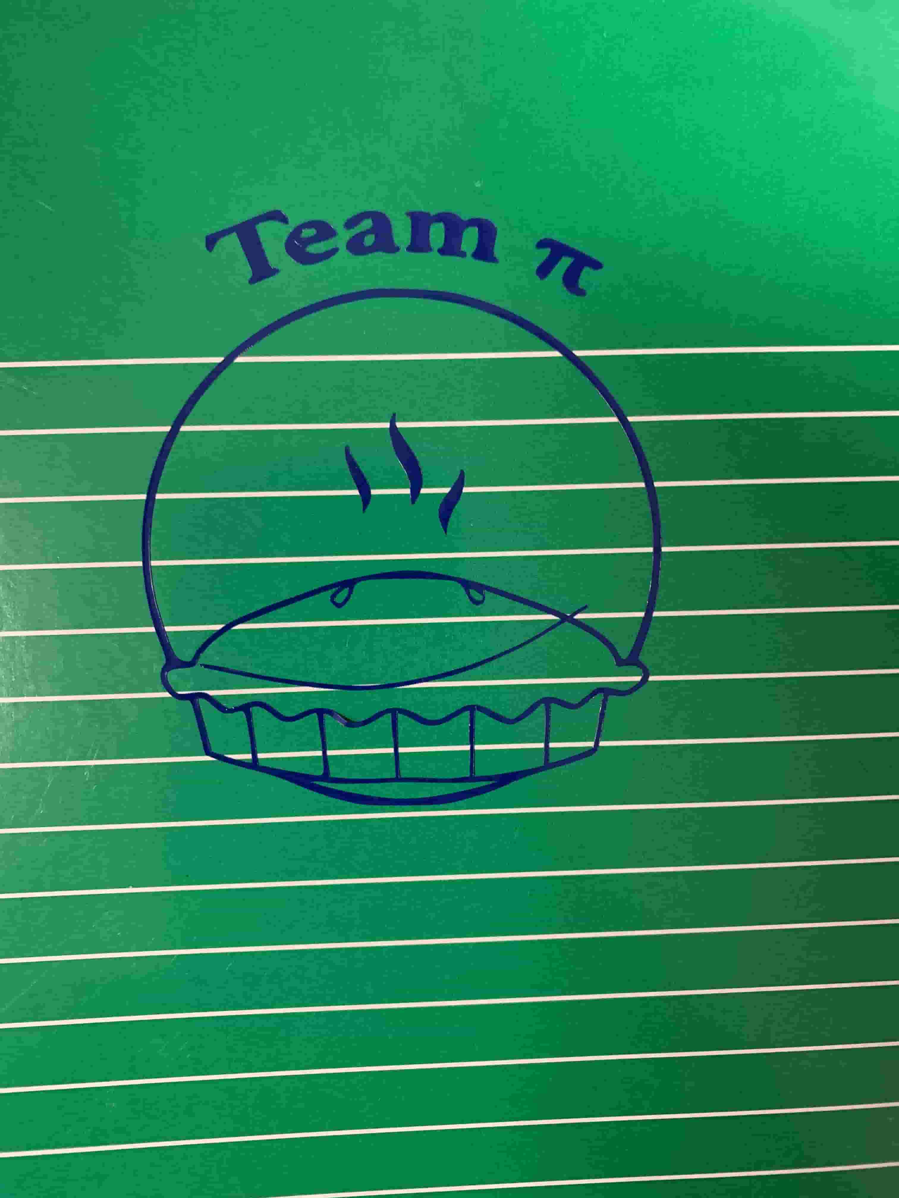
When it came to doing vinyl cutting my group and I though it would be cool to make a team logo. So that is what we set about to do. Our team name is team pi, and with that in mind we set forth. We all knew from the get go that two things had to be apart of the design: pie and pi. The original design that we made up was this beautiful colored image of a pie that looked like it could belong on an advertisement for a bakery. However, we were quickly informed that color was off limits since that would cause problems with the software we were using recognizing proper vectors to cut on.
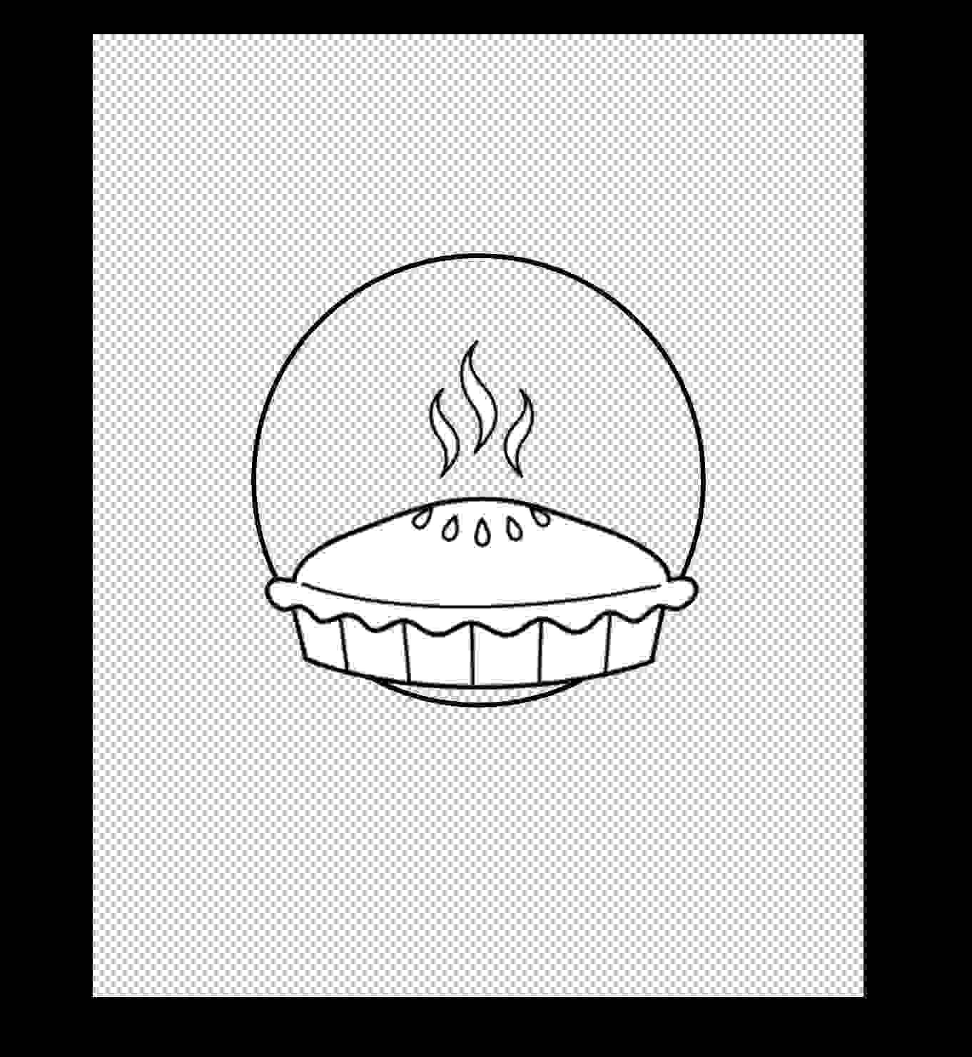
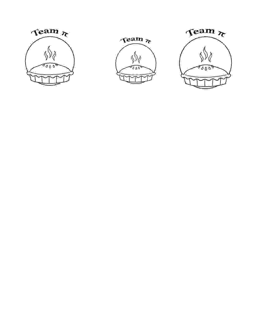
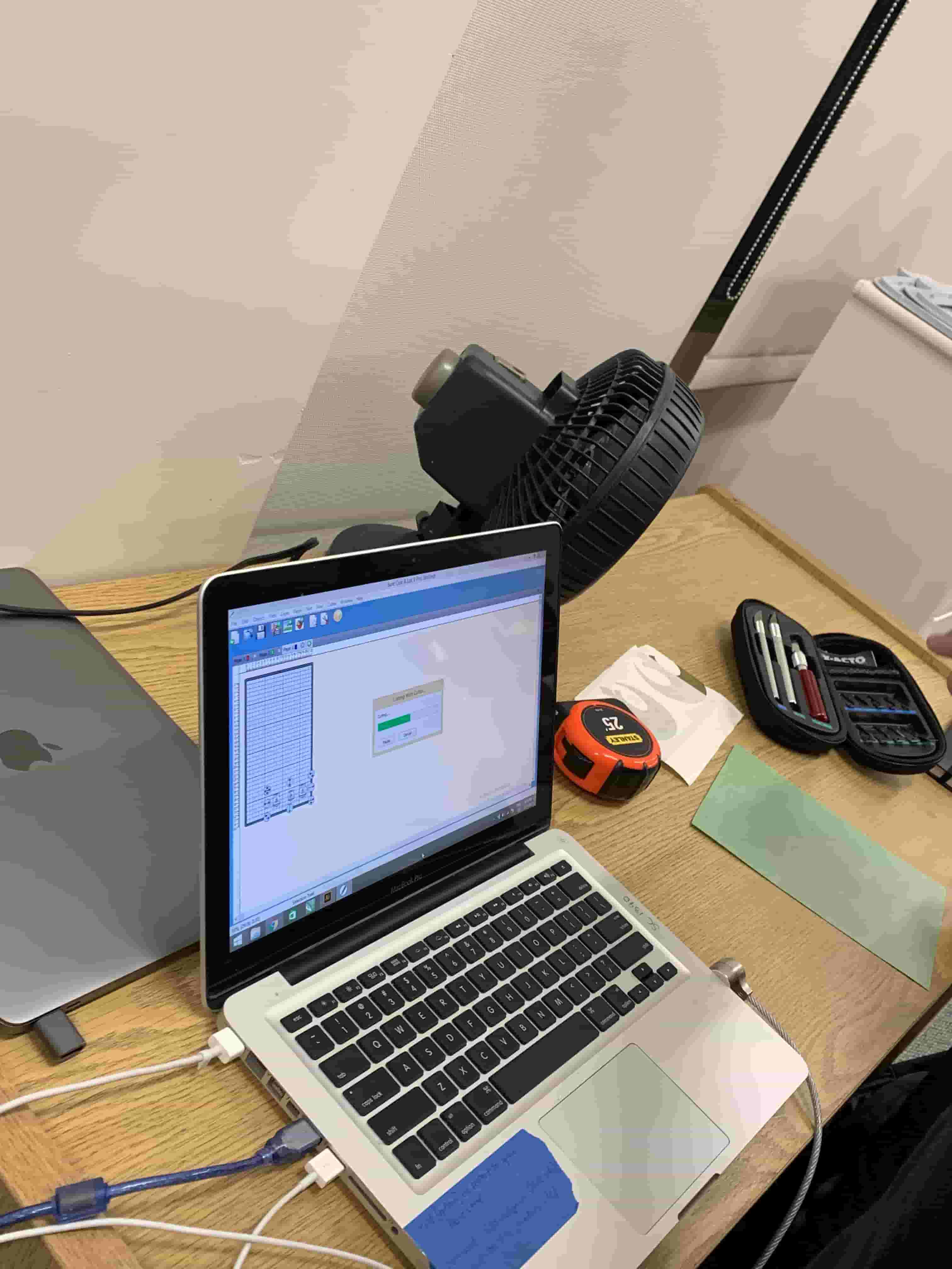
With our new knowledge, we struggled for a minute, since we knew how tricky it is to peel vinyl, to pick something that didn't offend our artistic sympathies, but would still be nice to peel. We ended up settling on a design that we were mostly happy with and sent it to computer so we could put it into the right software for the vinyl cutter.

I want to take this time here to say that David's concerns about the design were correct, and I was in fact wrong.
The Part where I was Wrong
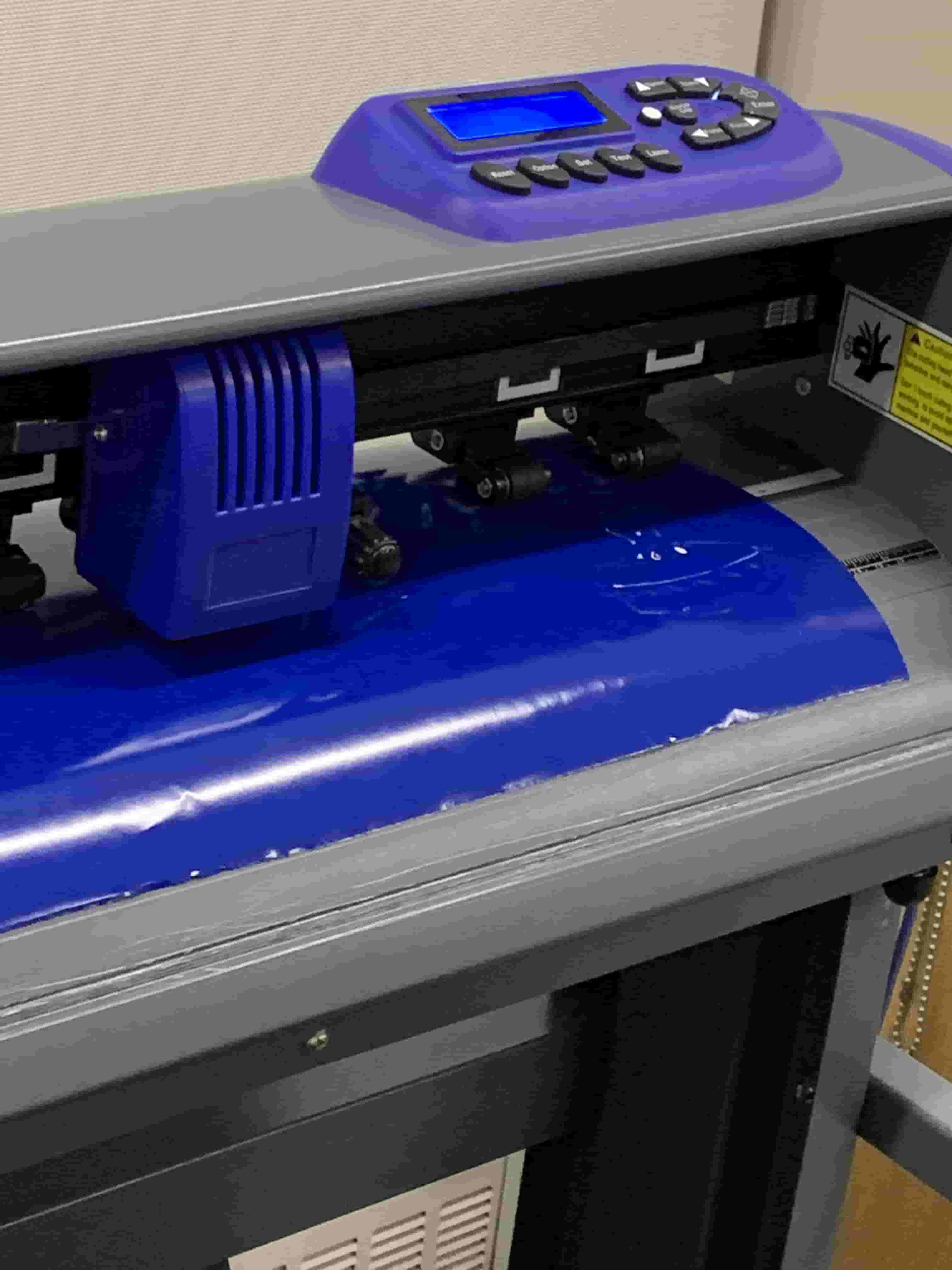
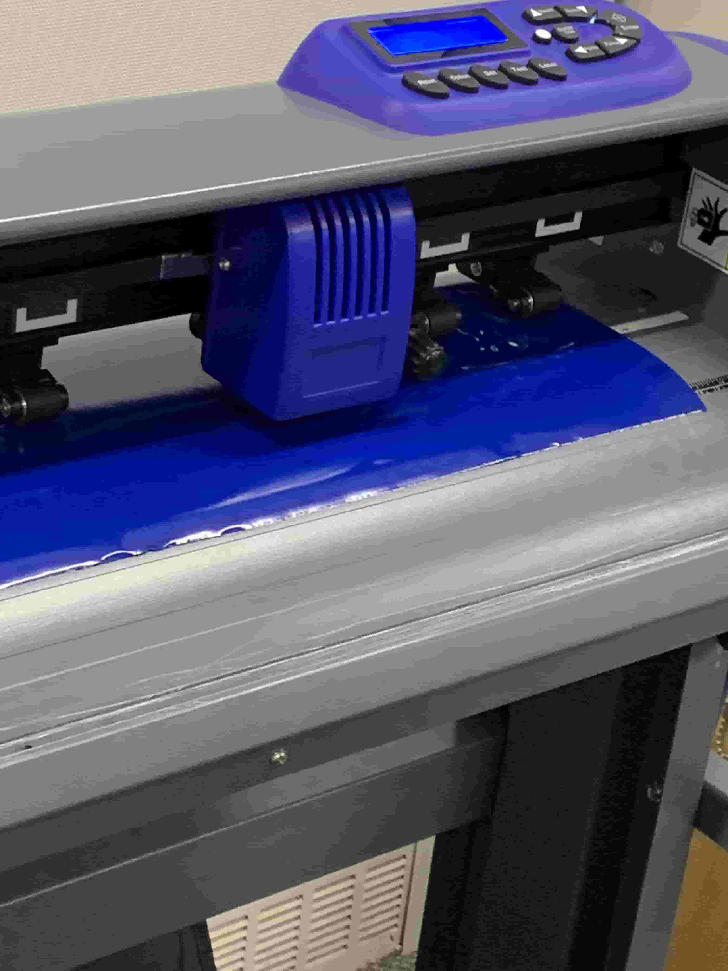
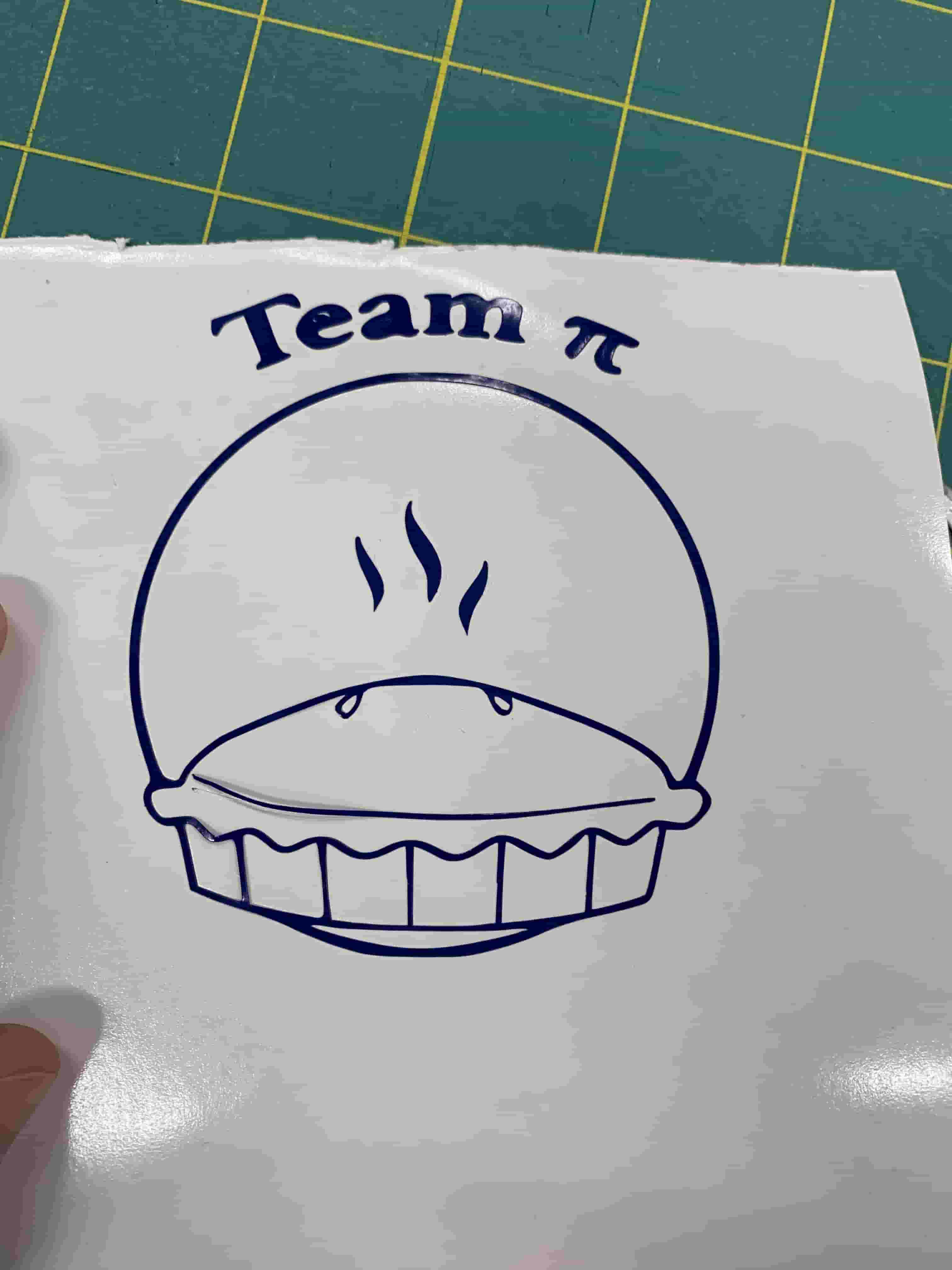
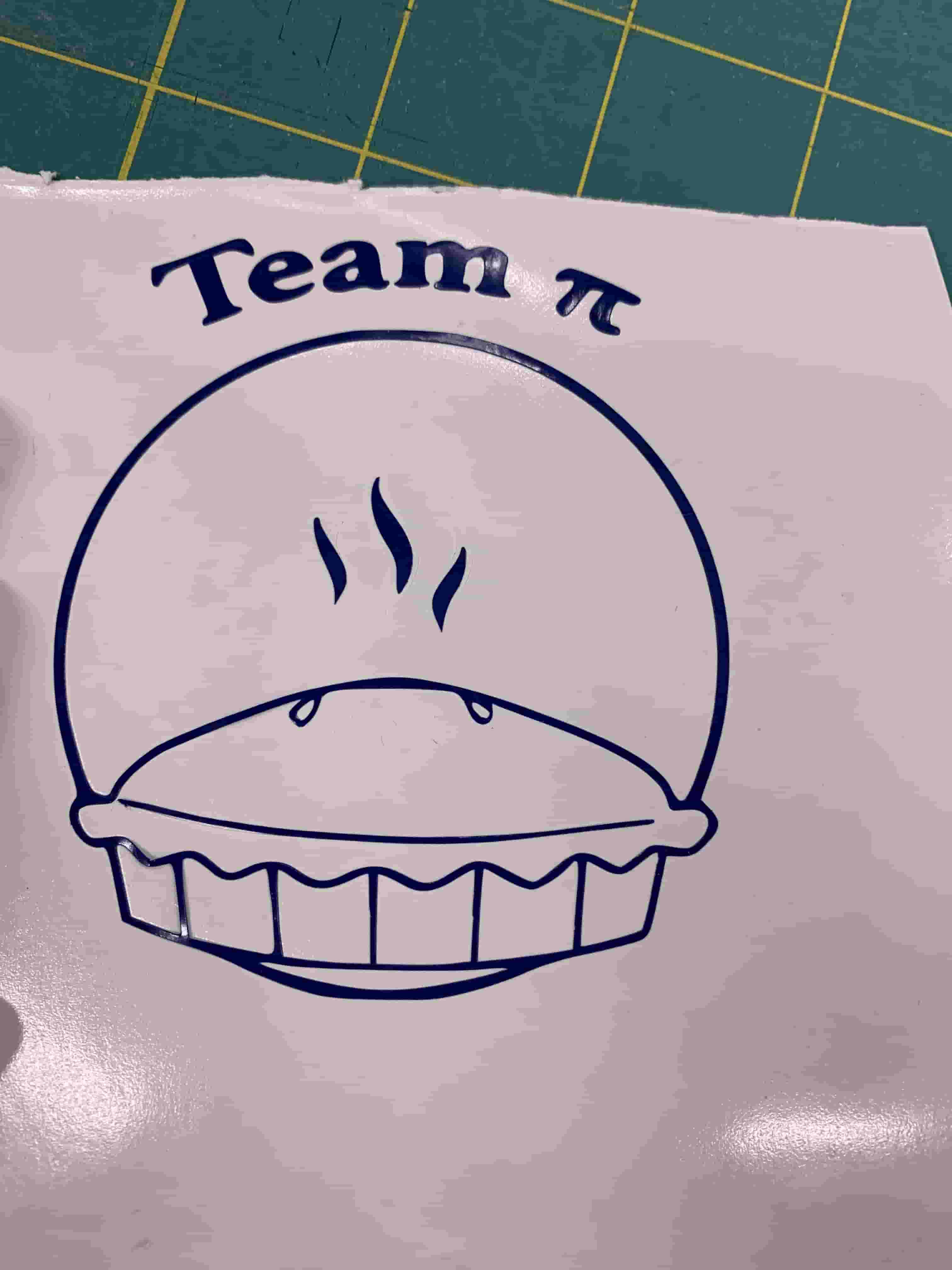
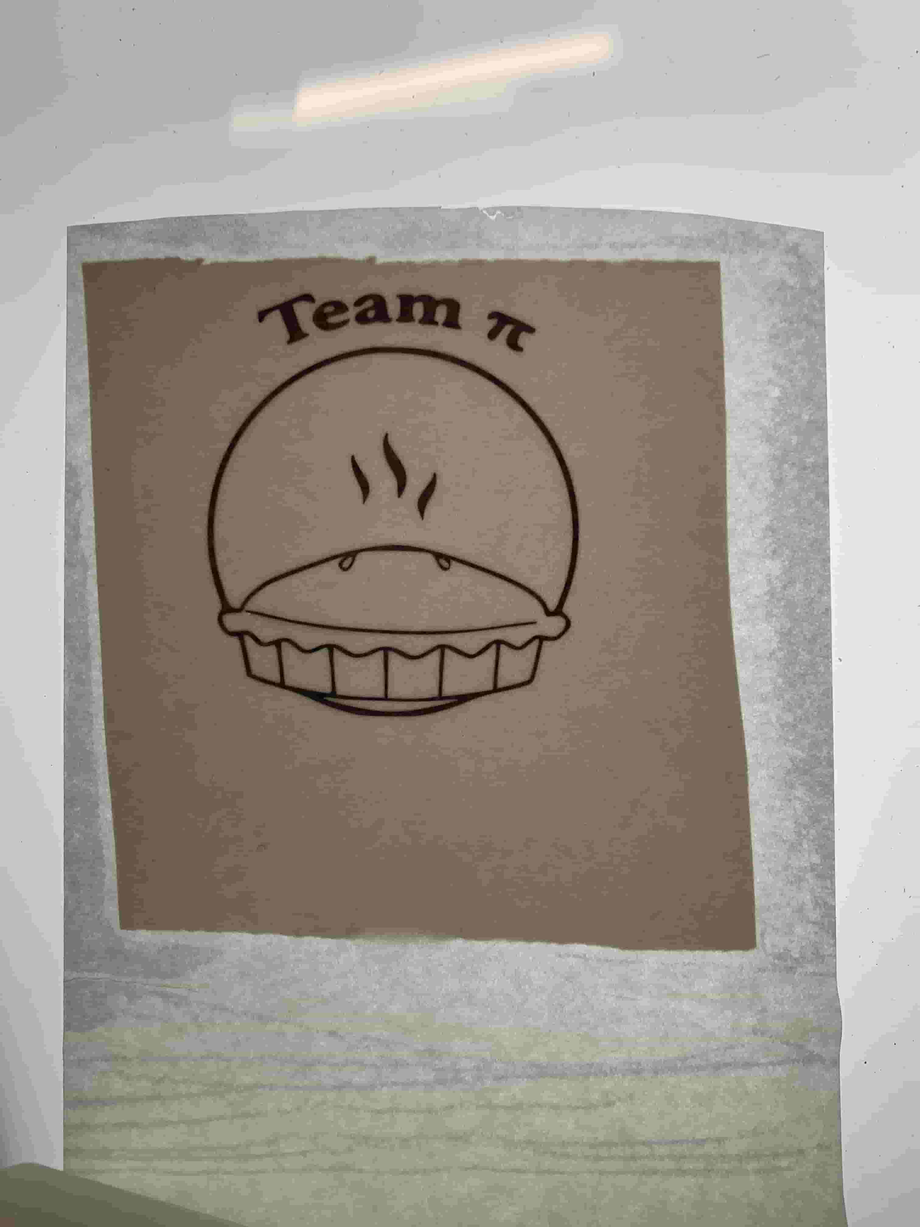
I was foolish. No better way to put it I looked at design, and flipped what was going to be cut in my mind. That flip made it seem like a nice easy design to peel. However when it is done properly then it was really difficult to peel properly we had alot of really thin lines that didn't want to be peeled. However it did cut very nice, but I think that is more on the machine than anything that we did.
Peeling was a pain, and unfortunately I didn't actually get to tape my full design since some got lost along the way. However I did definitly have something peeled and stuck to my notebook.
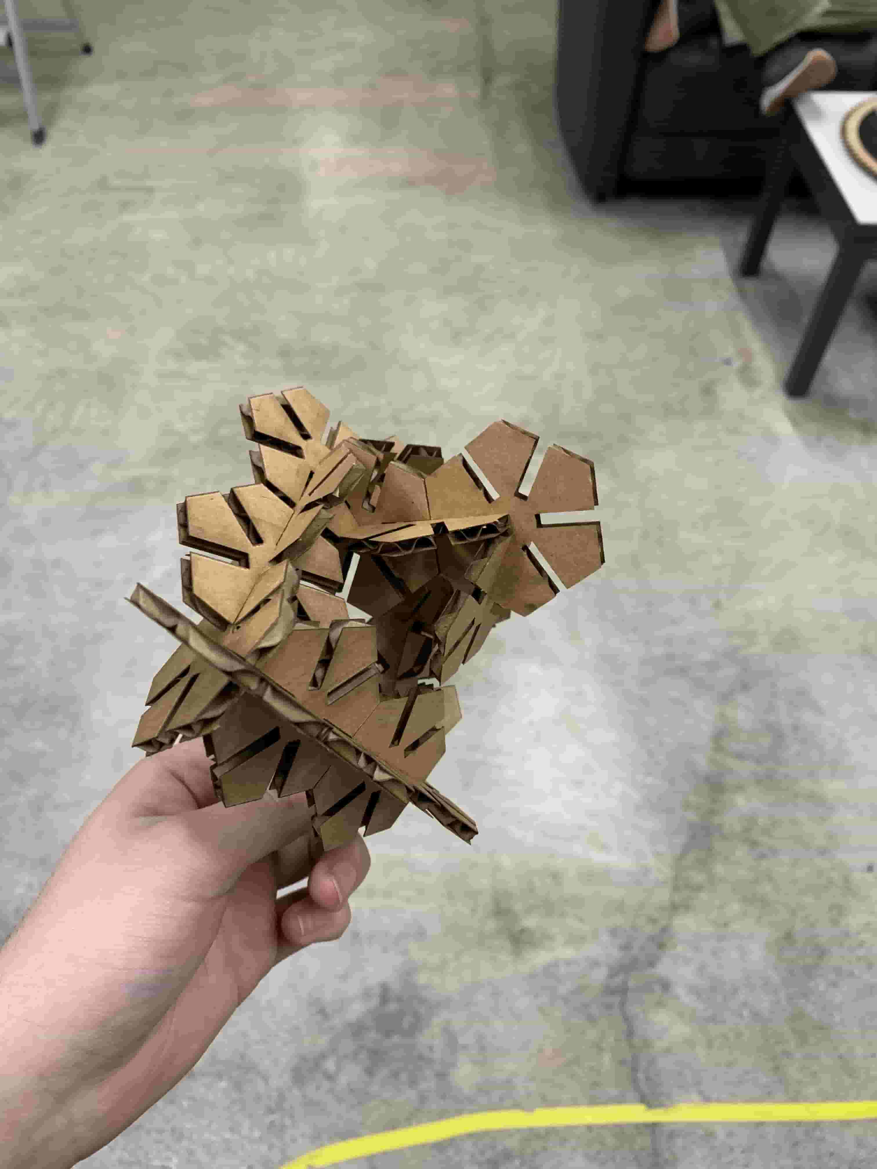
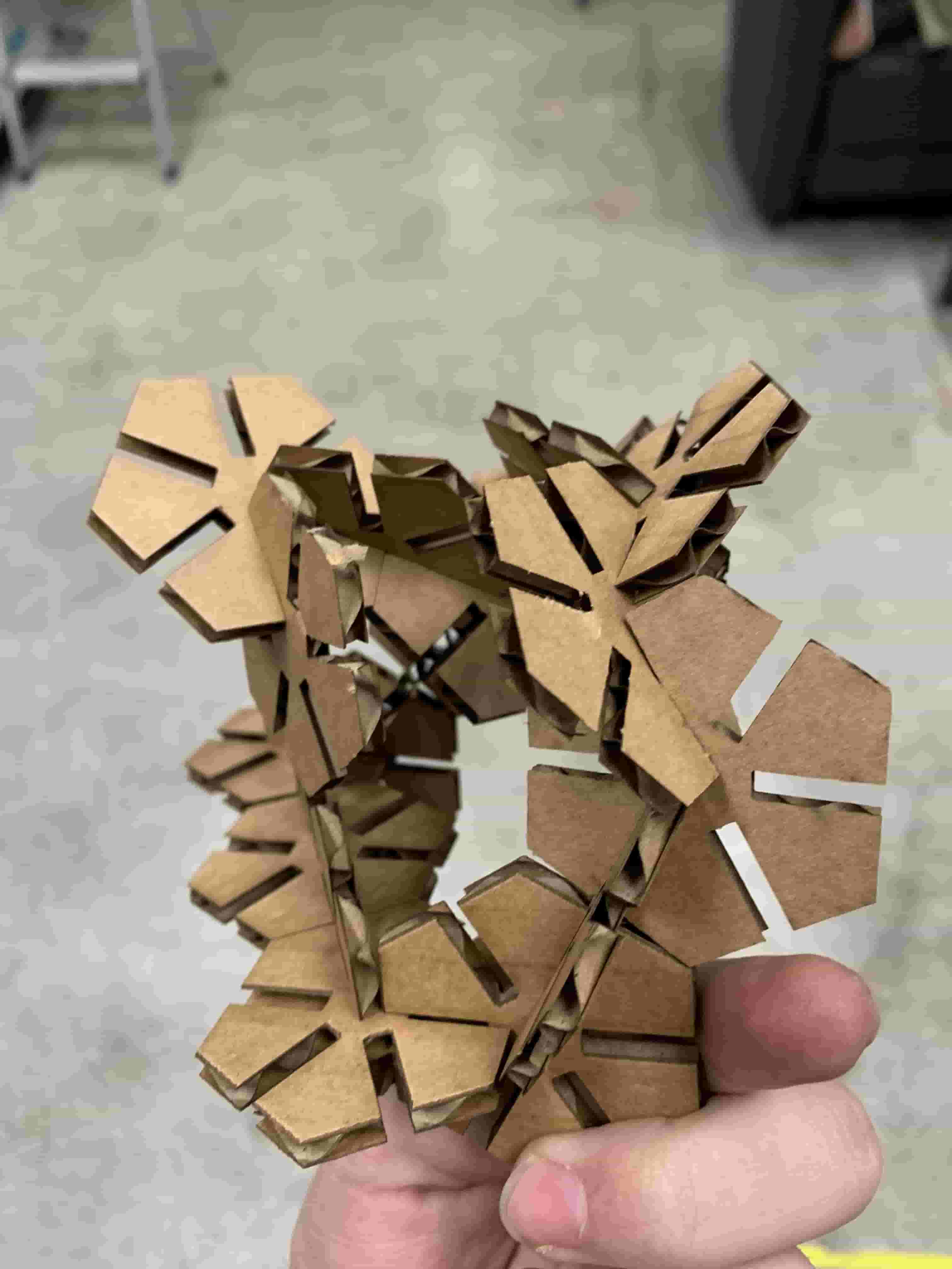
Construction Kit
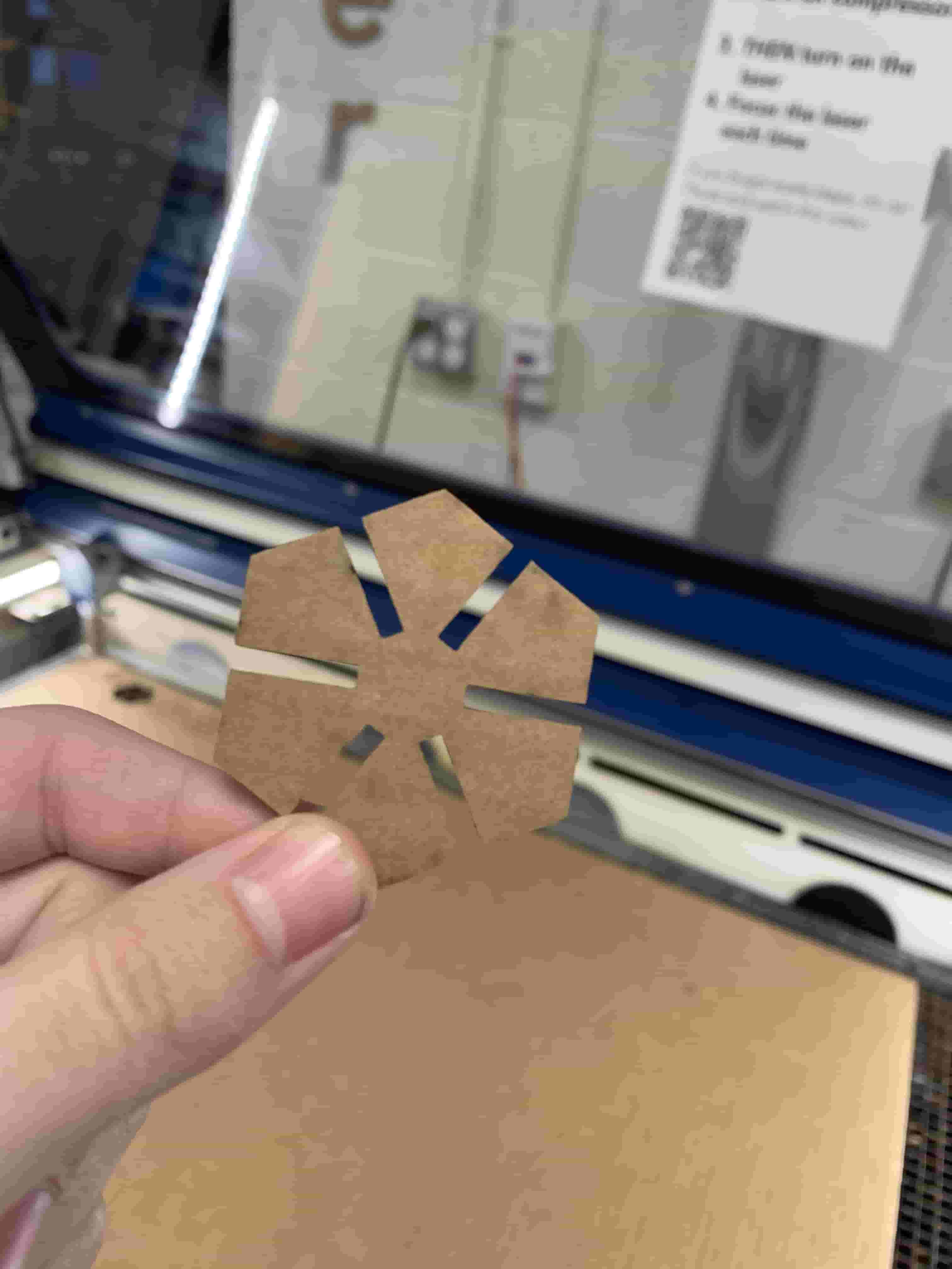
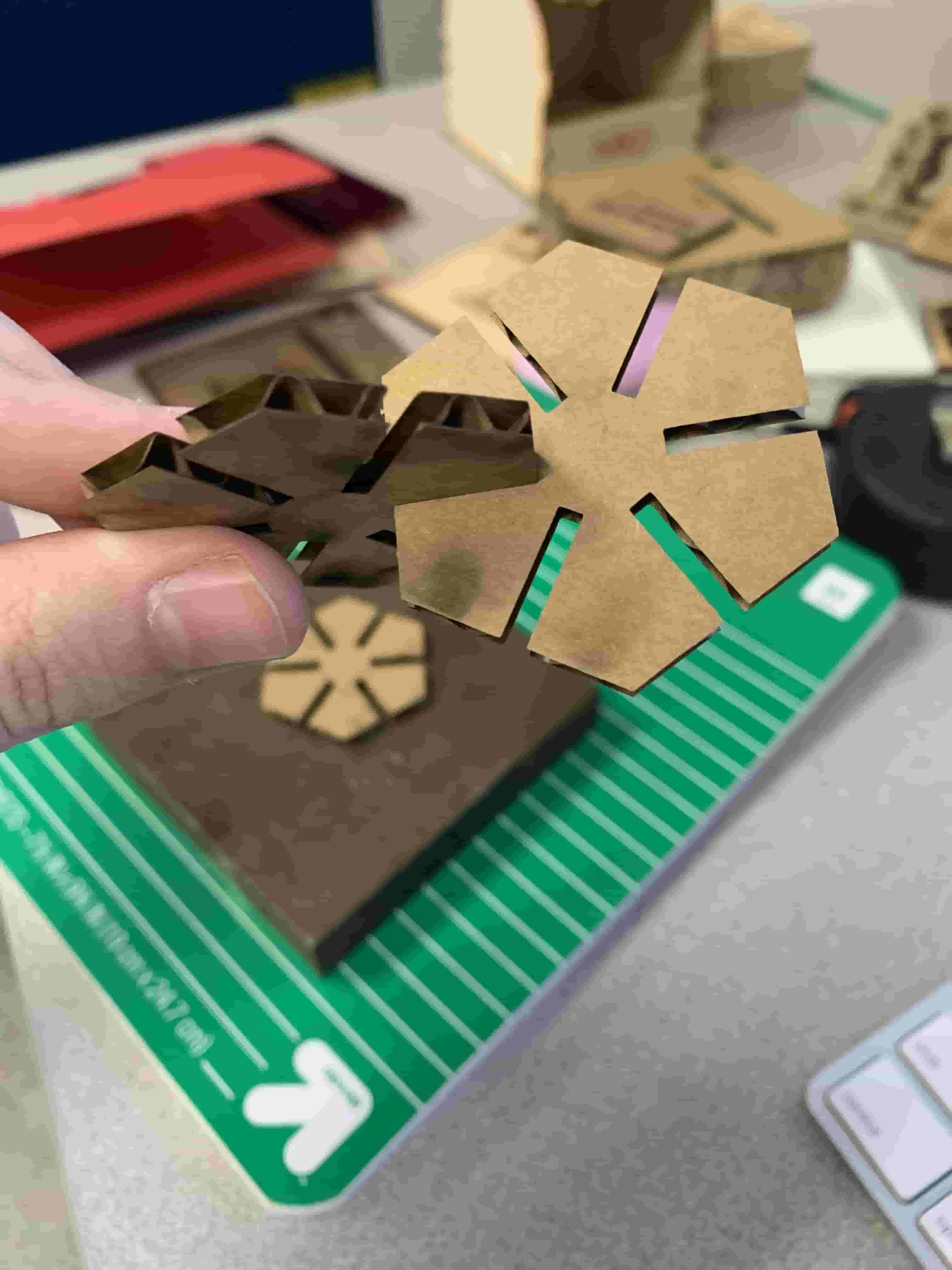
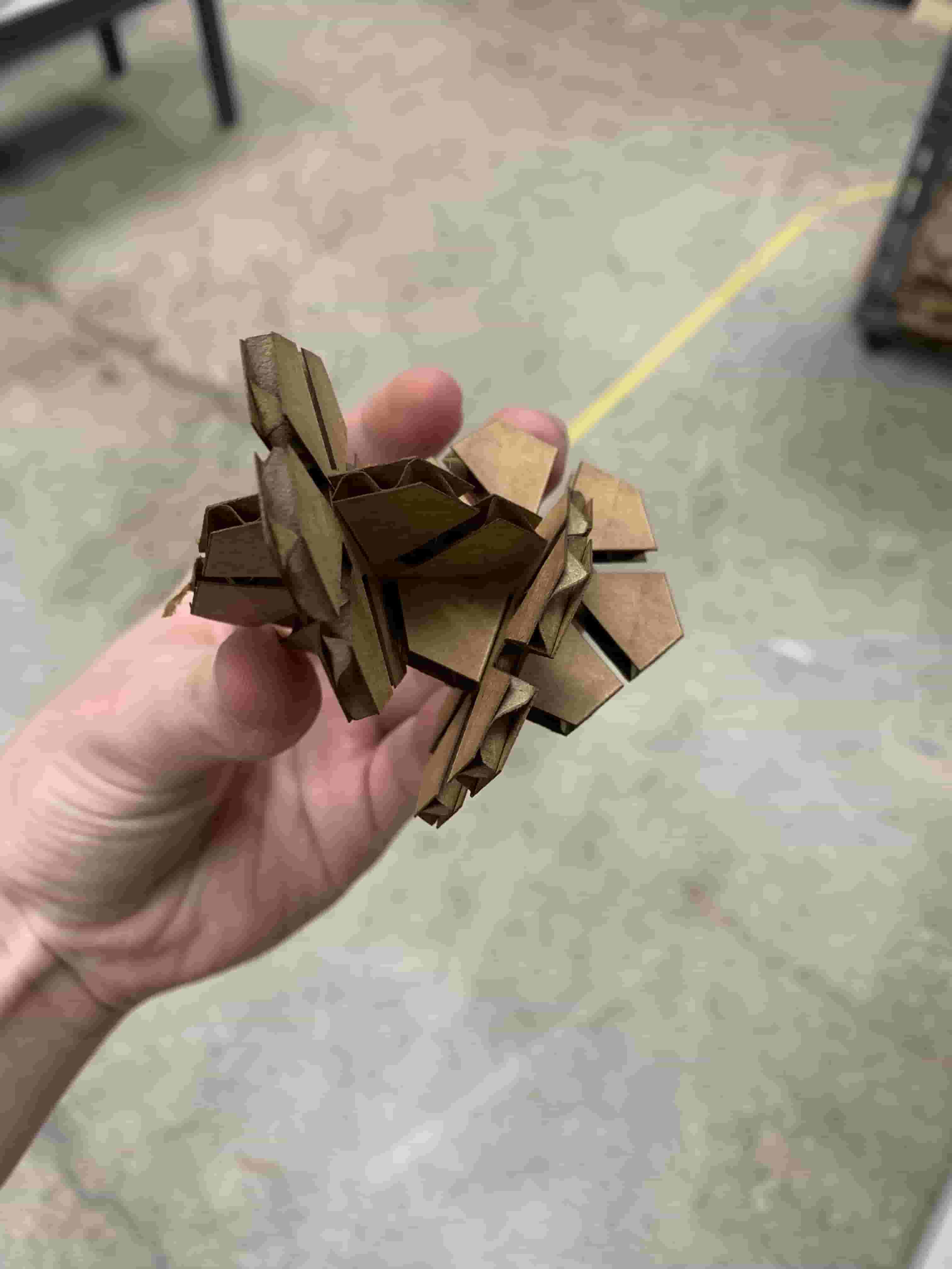
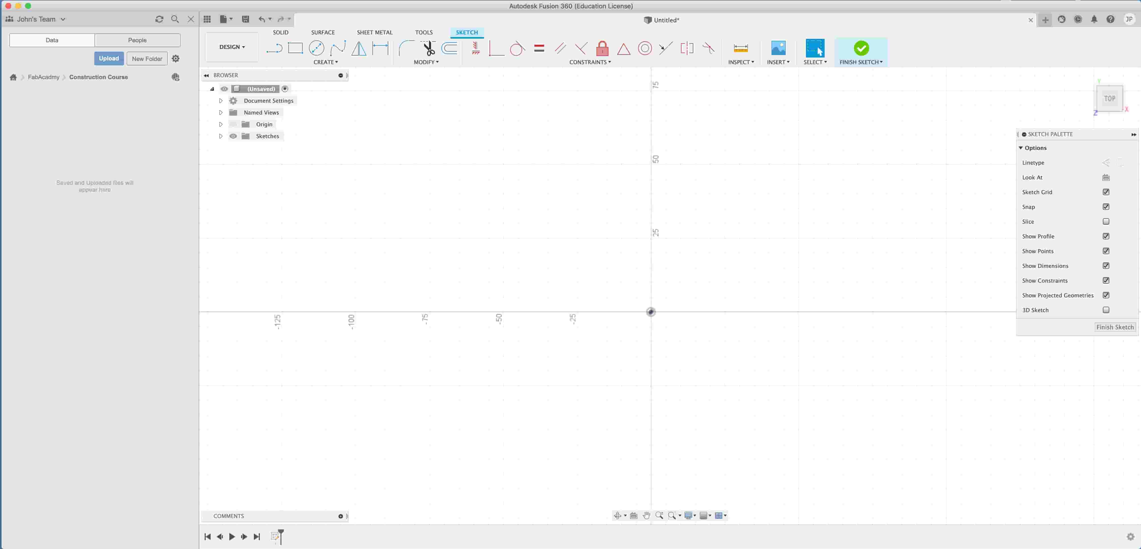
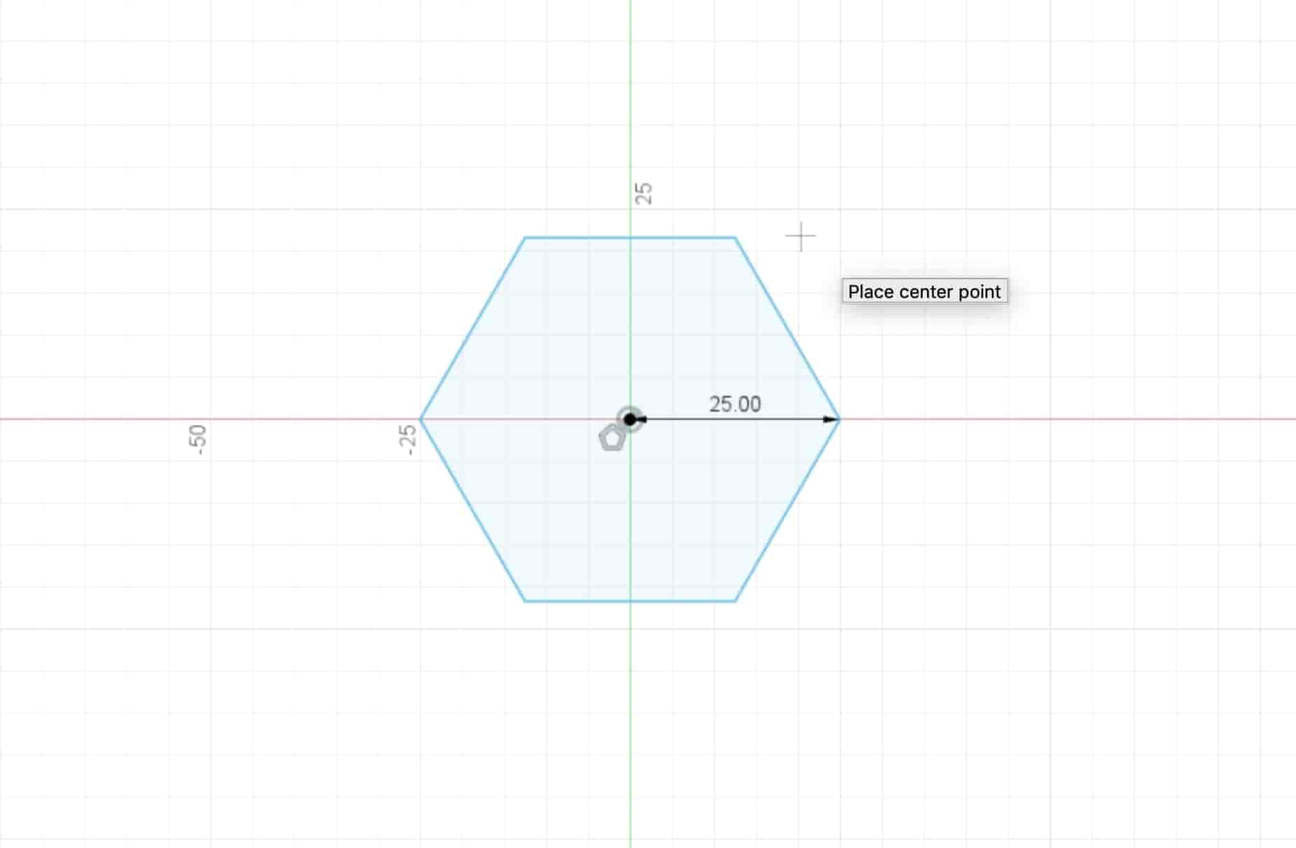
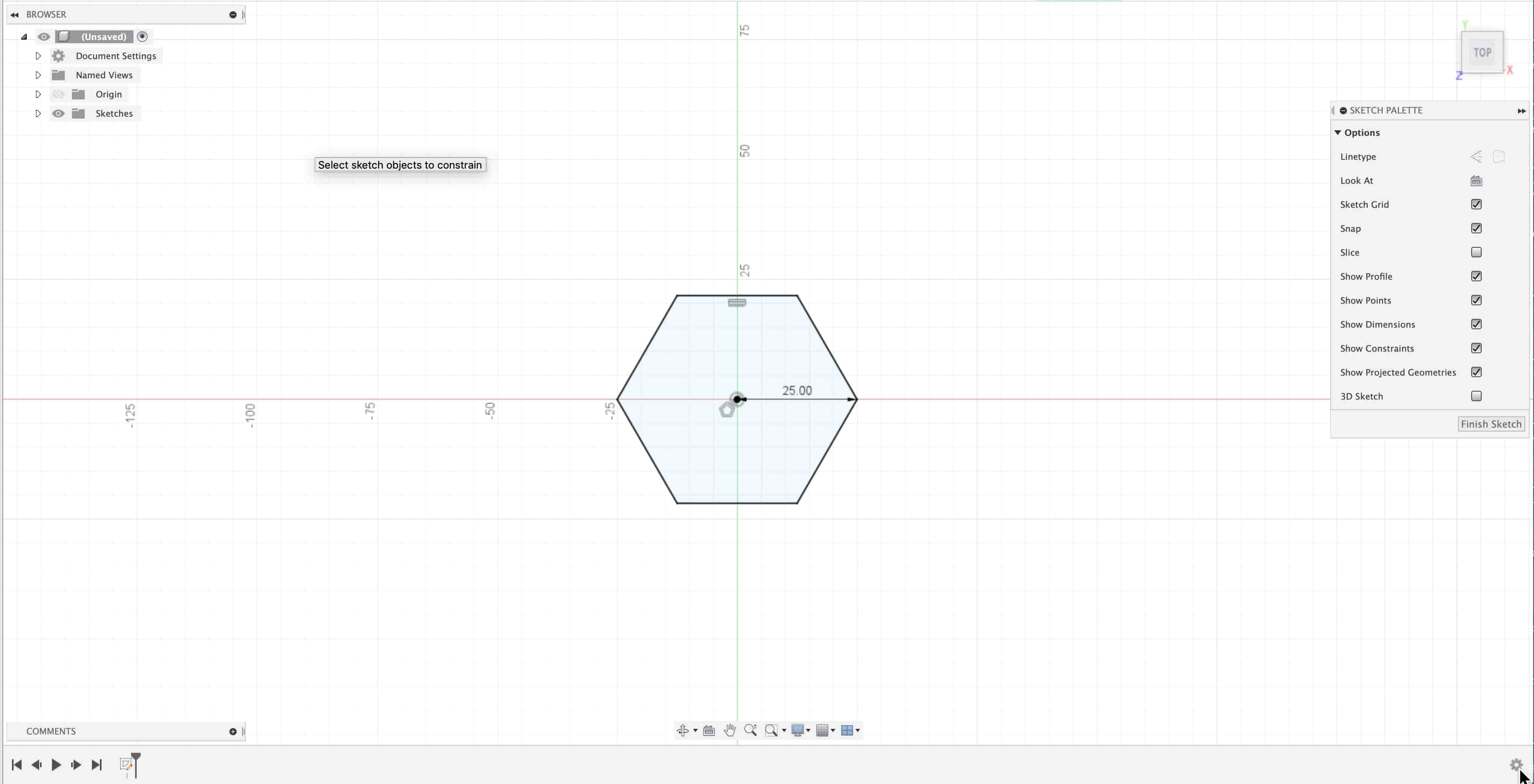
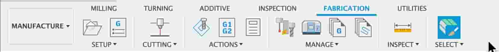
So when I saw the assignment coming over the horizon my initial thought was to make some interesting shape in fusion, and then from there just toss it in fusion slicer to get on of those super interesting trussed sort of design. However I talked to my teacher and she suggested making something that can be combined in any way. So my thought was that I would make a relativly simple shape with different slots in it so it could be combined with other shapes to make something interesting. I also thought it would be interesting to use Fusion 360's manufacturing tab so that I could get vector straight from Fusion instead of needing to do shenanigins in illustrator.
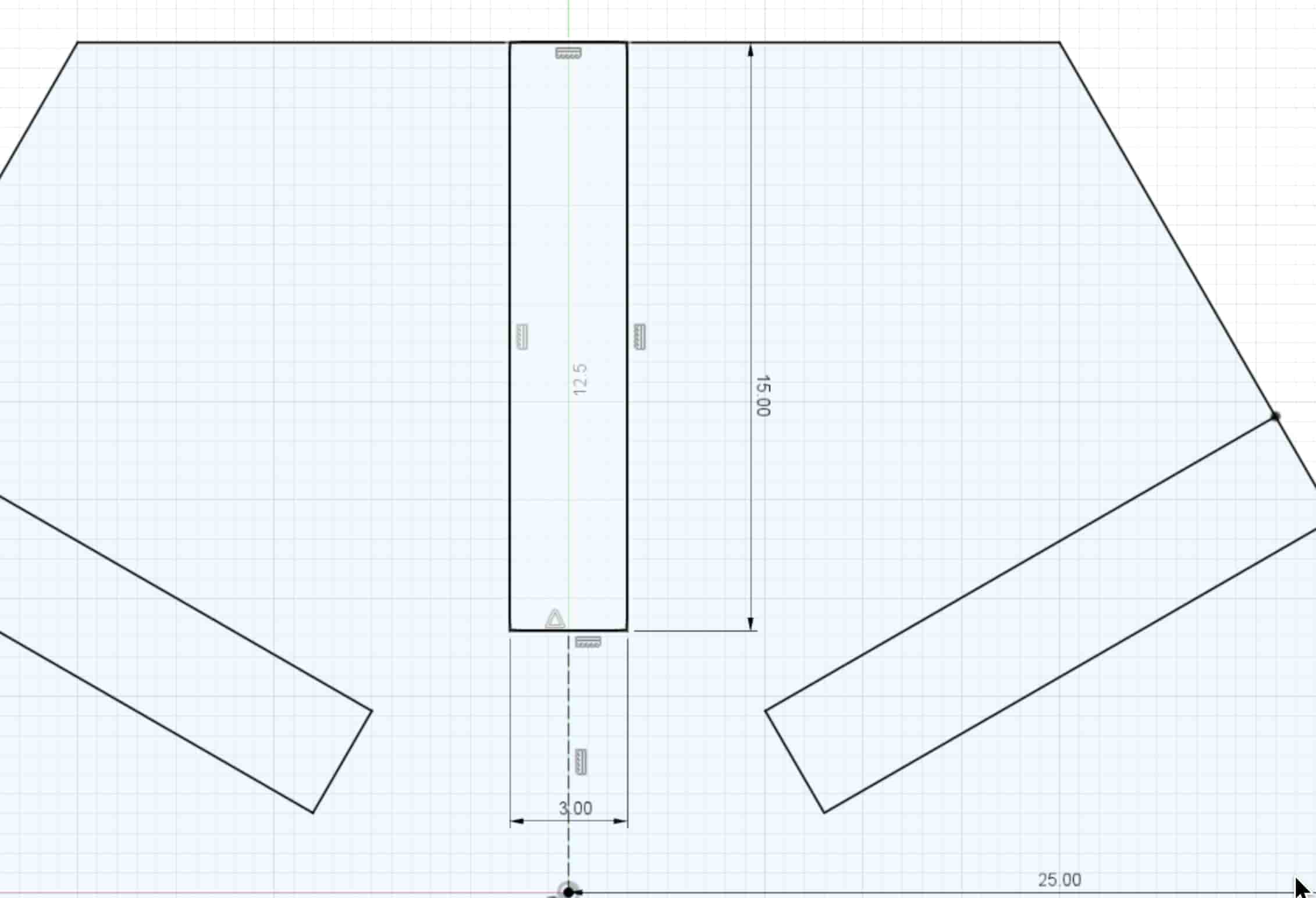

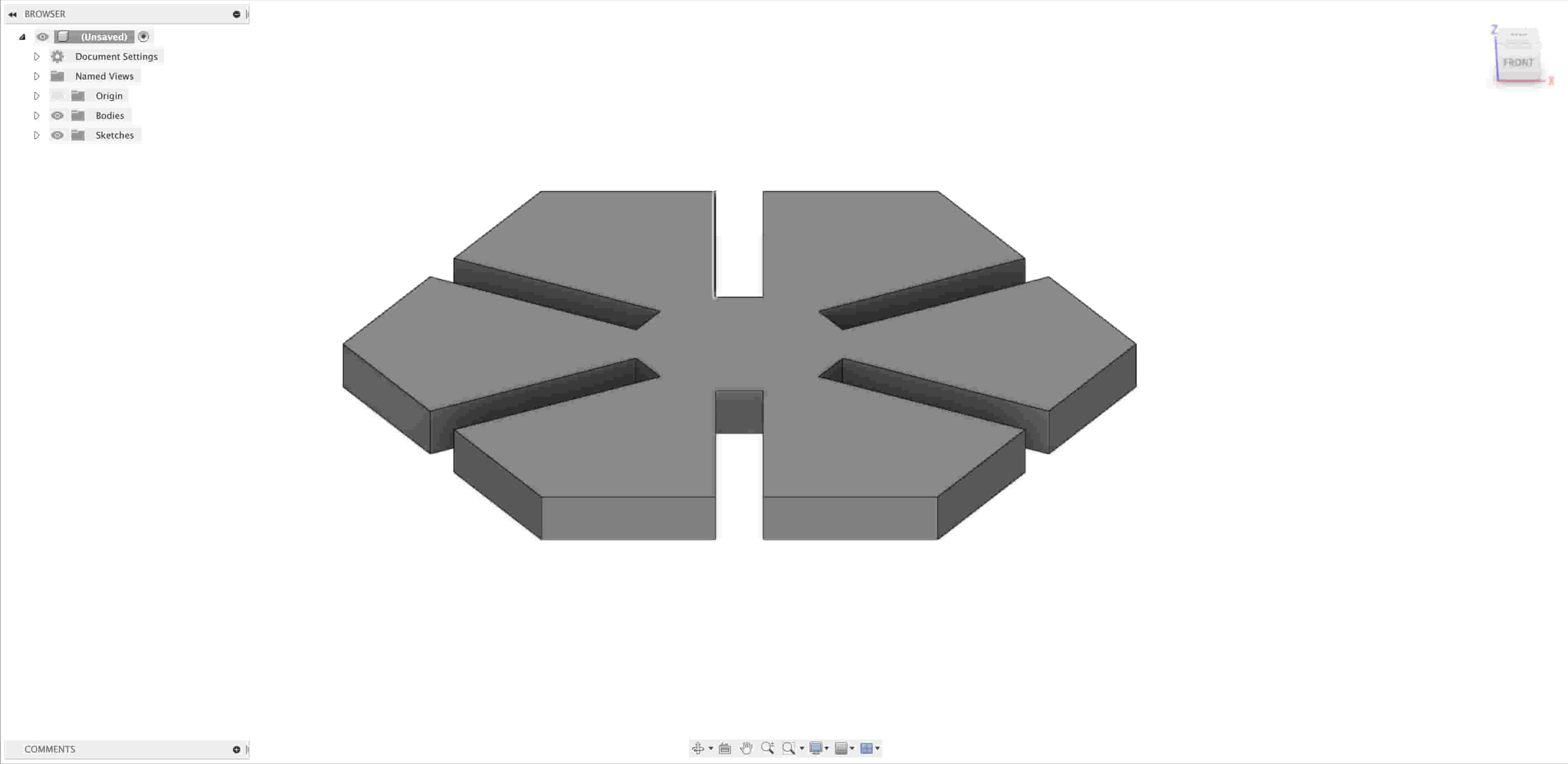
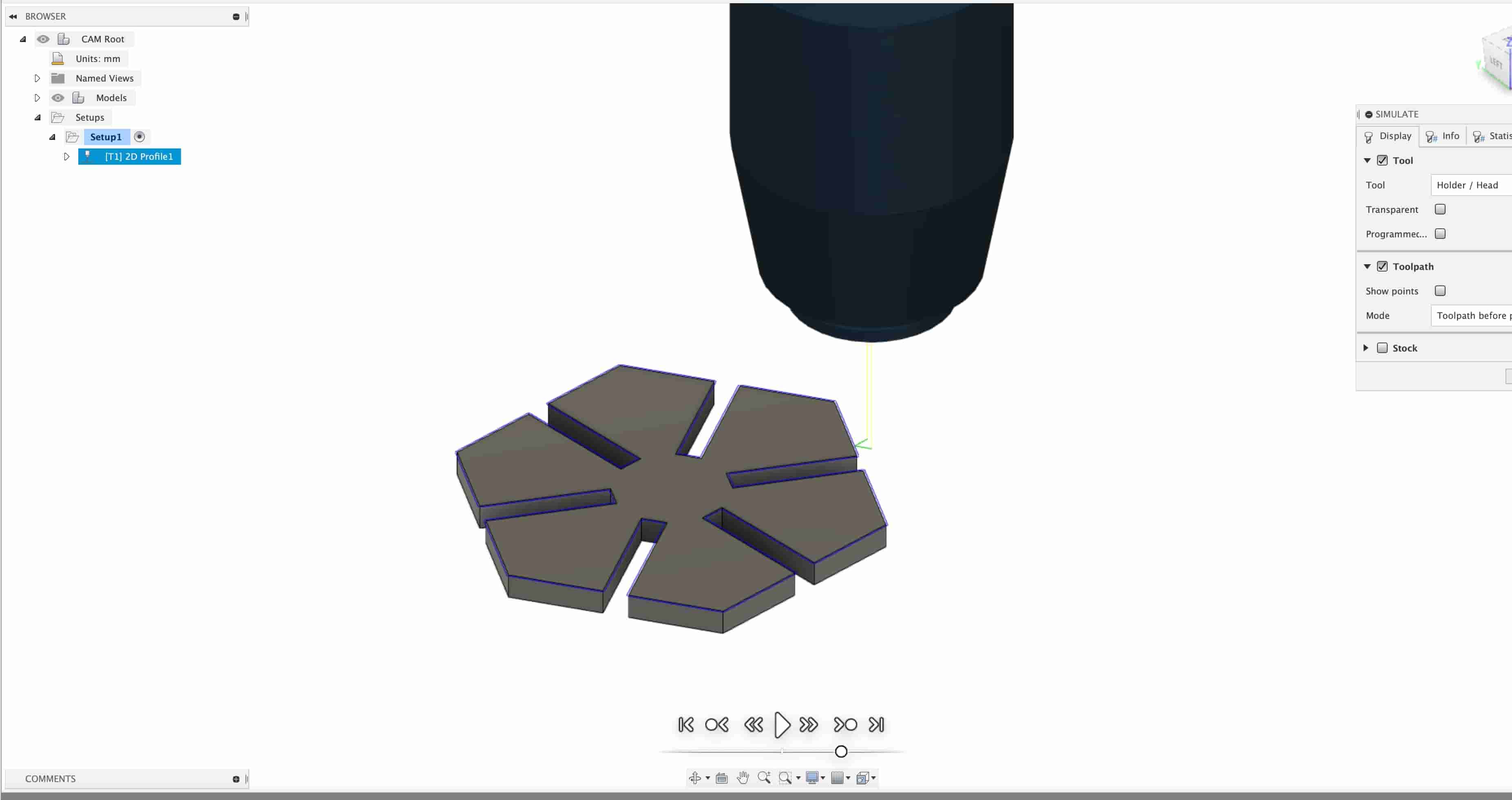
This next part is really disappointing to me just because I wasn't able to cut out as many little shapes as I would've liked. I ran out of time because some of the cuts I did ended up not working because the gaps were the wrong side. So I needed to work change the gapth width a couple of times. At the bottom of this page I'm going to have a download link and I'll have all of the files that I made from the different versions. I think that the amount of cuts I did ended up letting me build something pretty neat looking, and I think it would look even cooler as it gets larger, so I'm planning in my own time to print out a ton of these to try to make a cool cardboard thing.