Week
Four
Electronics Production!
Jargon.
Feed Rate
Feed rate is the velocity at which the cutter is fed, that is, advanced against the workpiece. It is expressed in units of distance per revolution for turning and boring (typically inches per revolution [ipr] or millimeters per revolution).
For this machine it can function from 6-1800mm/min
Spindle speed
The spindle speed is the rotational frequency of the spindle of the machine, measured in revolutions per minute (RPM). The preferred speed is determined by working backward from the desired surface speed (sfm or m/min) and incorporating the diameter (of the workpiece or cutter).
For this machine it can function between 3000 - 7000 rpm.
Plunge rate
Plunge rate is the speed at which the router bit is driven down into the material when starting a cut and will vary depending on the bit used and the material being processed. Sometimes it is possible to cut at a faster feed rate by increasing the spindle rpm.
This is not specified on the manufacturers website, although I suspect that it is limited by the same speed situation as the feed rate.
Depth of cut
The measurement. (normally in inches or millimeters) of how wide. and deep the tool cuts into the workpiece. Speed, feed and DOC work together to. determine the Metal Removal Rate (MRR).
This is going to be dependant on what sized bit you are using on the machine moreso than the machine it's self.
Tooling
Tooling, also known as machine tooling, is the process of acquiring the manufacturing components and machines needed for production. The common categories of machine tooling include fixtures, jigs, gauges, molds, dies, cutting equipment and patterns.
Group Project
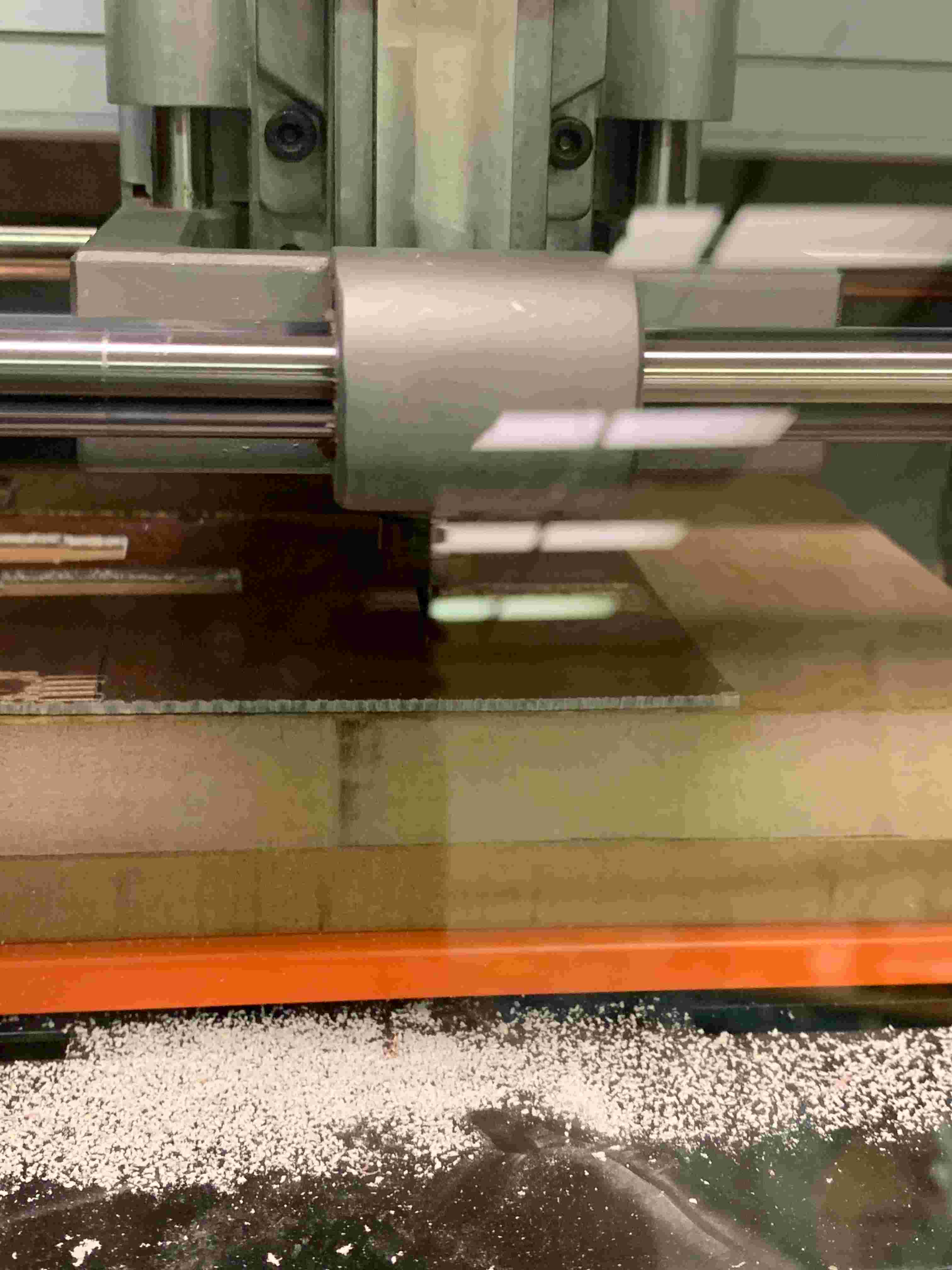
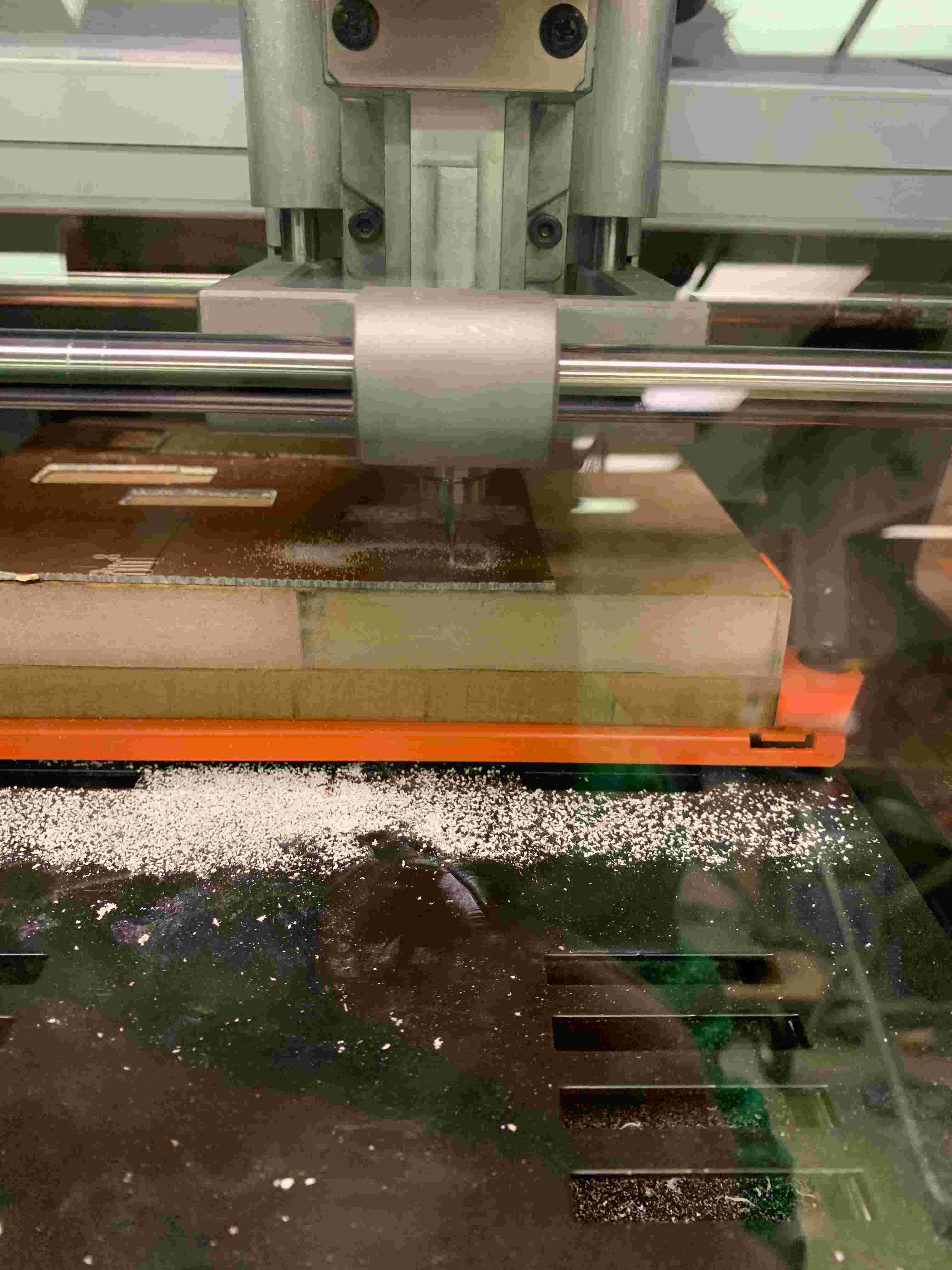
We struggled quite a bit in actually milling this board in truth. In our time working on this we never actually finished milling the piece. Now what problems did we run into? What a wonderful question! For one the first time that we started working on it in mods we accidentally opened the wrong program. We knew that it was a server program under Roland Mill, however we accidentally picked MDX-20 as opposed SRM-20. Now if you were wondering whether or not this would be a big deal turns out yes. What basically ended up happening was it milled out a tiny little square of all of the copper as opposed to an actual shape.
This was admittedly upsetting to us, but even worse we didn’t even have that happen the first time we tried to print it. The first time we tried to print it there was an issue with the Z-axis so instead of milling it just slightly skimmed over the surface. Since this issue occurred we weren’t able to uncover our larger mistake until we actually did the whole process twice.
Twice wasn’t the end of it though. Since at this point in time we still had a little ambition and faith in our own capabilities, so we went back through to actually pick the right server program. This naturally led us in the right direction in regards to size, and actually, ya know cutting something out. Our own incompetence still got in our way though, and we proceeded to mess up the zero point for the Z-axis about three times. One time, we had the axes perfectly set and felt really good. However when we went to cut it just didn’t cut at all, it stayed off of the surface the entire time. We assumed that it may have been a file issue.
In retrospect we now know that the team member who taped the board to the machine did a poor job, and the piece was exceptionally uneven. Nonetheless we went back to mods to try again. This time however the team member who was doing the work in mods made some mistakes, that the rest of us didn’t catch, and forgot to properly zero everything, so when we ran this file the bit shot up about 20mm and started carving away our board out of thin air.
Luckily after going through fixing that issue, and at this point a newly discovered tape issue, we went at it again, and very neatly carved out our board. Yay! The celebration was undercut however as when we went to actually cut it out of the larger piece, we messed up again, and the whole thing didn’t even cut. At That is where we find ourselves now. With our once hopeful eyes now downcast, defeated by a machine. However for as much as it was a discouraging, moral breaking event, I think we’ve learned a lot. At very least we’ve learned plenty of ways to not use the mill and I think that as we go forward we’ll all be better makers for having gone through this. At very least I hope we’ll be able to actually mill a board.
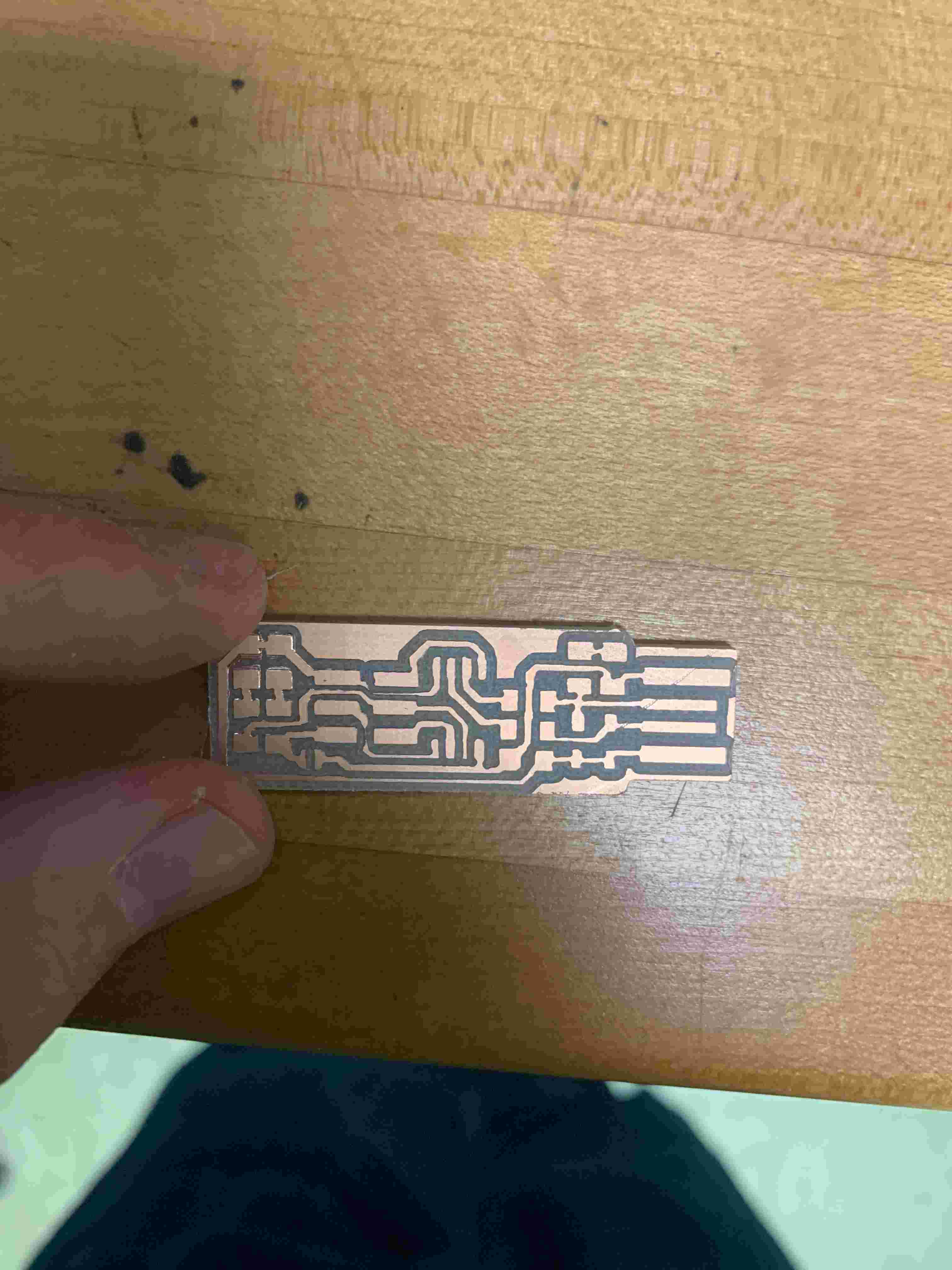
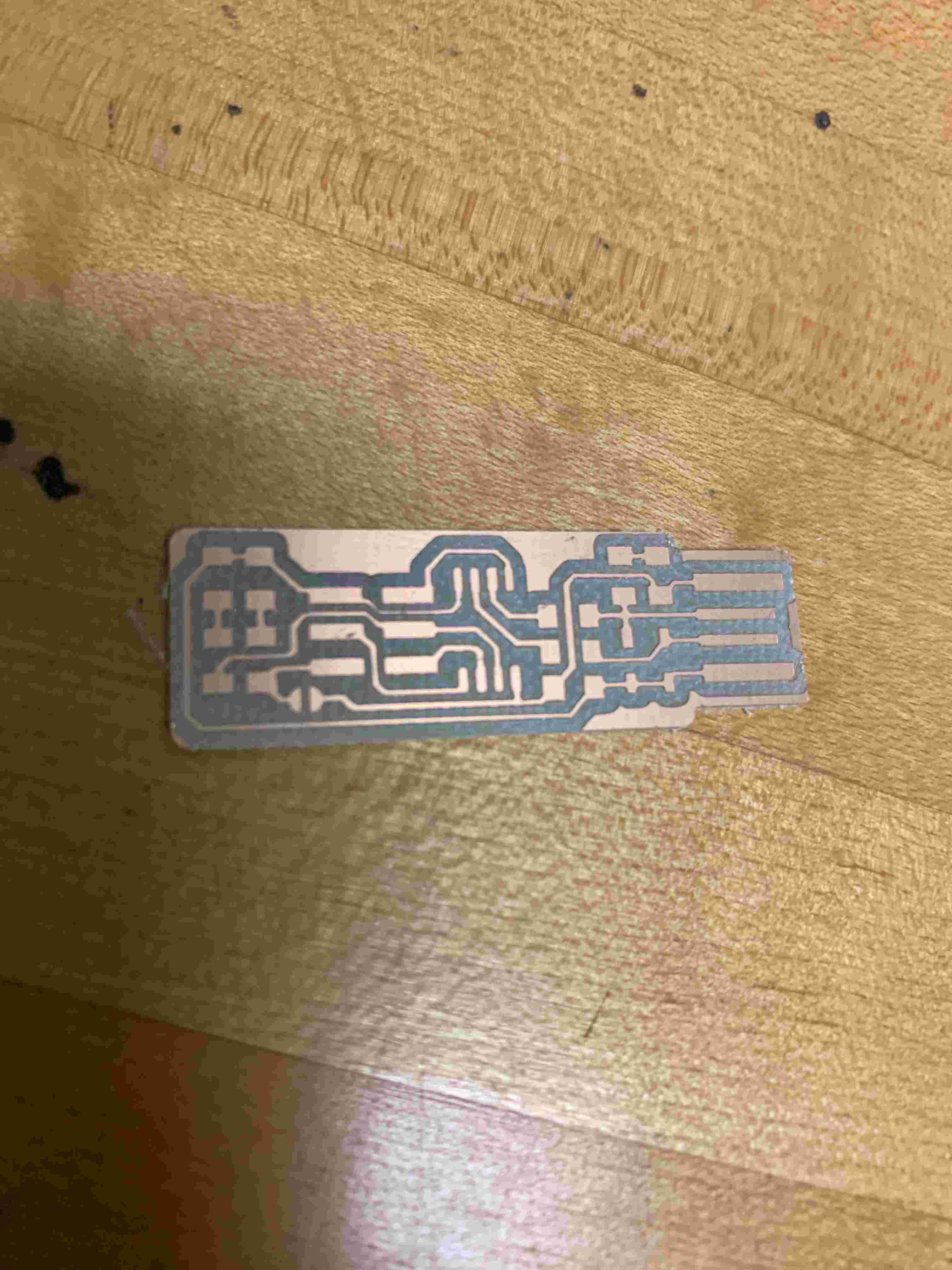
We Milled a Board!
It took us quite a while but we did eventually manage it. For this cut we used a 1/32 inch ball nose bit. Looking at the calibration it looks as though the line cuts came out very well. That is with the exception of the one on the top that is a bit thicker then it should be. I attribute this to the fact that the cutting surface isn't very flat. I think that is alo why you can see that we had some problems on the cut out at the top of the board. Another fact that could be contributing to these problems could be fact that work holding isn't great on the machine, so the board isn't properly secured.
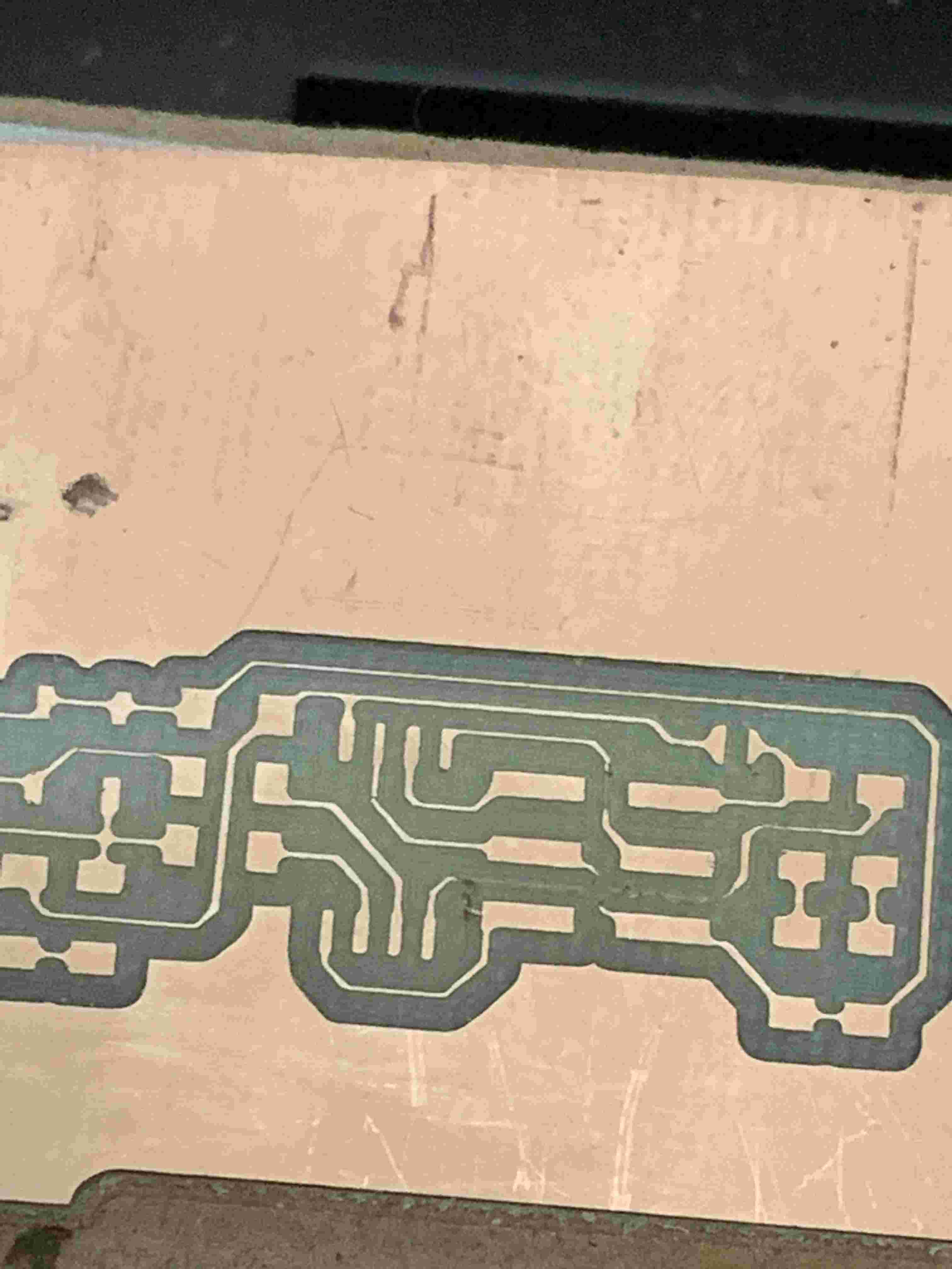
FabTinyIsp
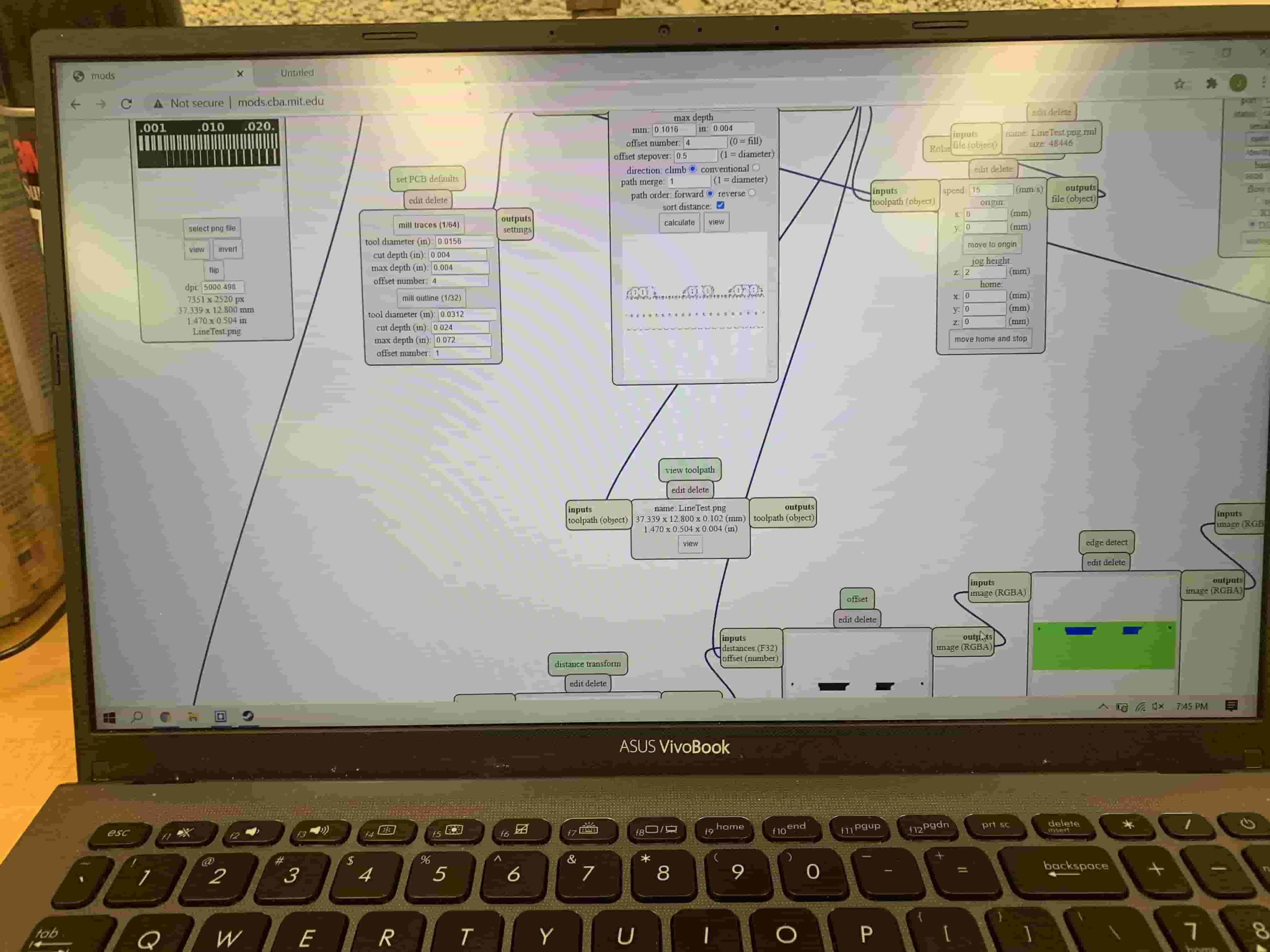
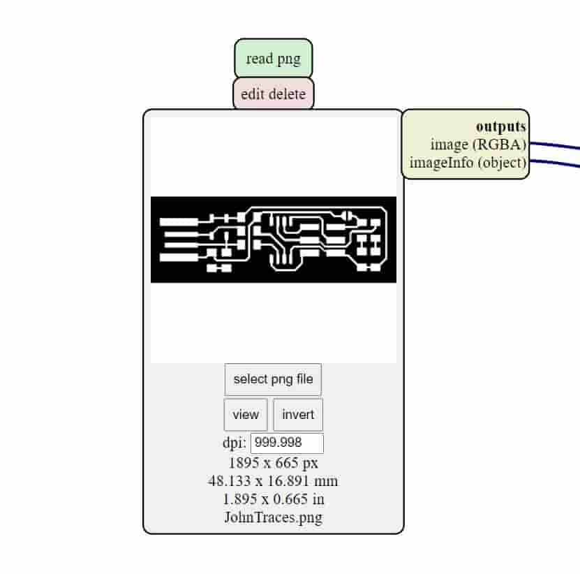
The next part of our project was making a FabTinyISP board. I'm happy that doing this I had more success than I did milling the test board with my group. To start with this porject I went onto the fabacady site, and got the .png's that have the Traces and the outline Cutout.
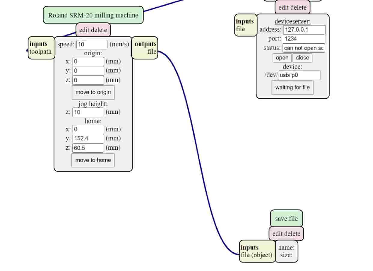
Once I had the .png files then needed to import them into mods to create files that would be readable by our mill. Since we don't have mods hooked directly up to the machine we needed to edit the flow through so that it saved the file that I was creating as opposed to sending it to the machine. I also had to make sure to set the zero postion to being all zeros, so that I could change them with the software we are using for the machine.
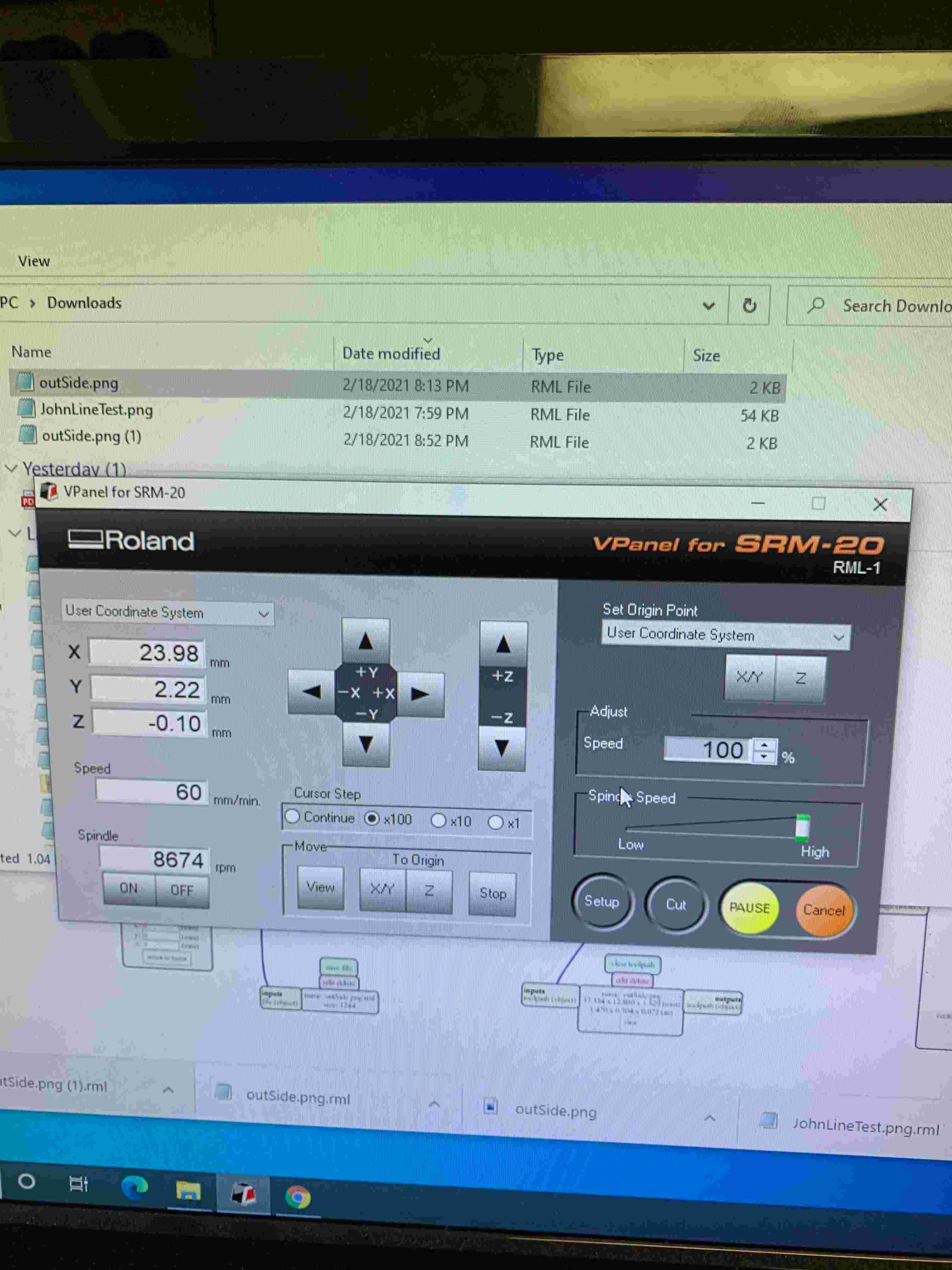
Yay! So, up to this point things have been going well. At this point things begin to change. So I have my file on the computer we are using to control the machine, and I work to properly zero the bit so that I'm minimizing my footprint on the larger piece of pcb, and also actually have my bit touch the material, so that it'll cut properly. I felt like I did this pretty well, and at this point I import the files that I need into the software we are using called Vpanel, and start the carving process. At this point I should mention, in case it can't be assumed, I did in fact put in the bit to actually cut. So when it started cutting it didn't go accoding to plan about 6 times over two days. In those days I recreated my cut file about 4 times. Through out this process I had three main issues. Sometimes the bit would be too high and it wouldn't actually carve out the paths properly. The other time is that in the bit traversing it would incidentally break a couple of paths. The third problem which I didn't see often was the bit would carve out too much material, and the paths would end up being butchered to the point that they weren't actually passing power throughout. However even with these problem I did eventually end up with a nicely cut board.
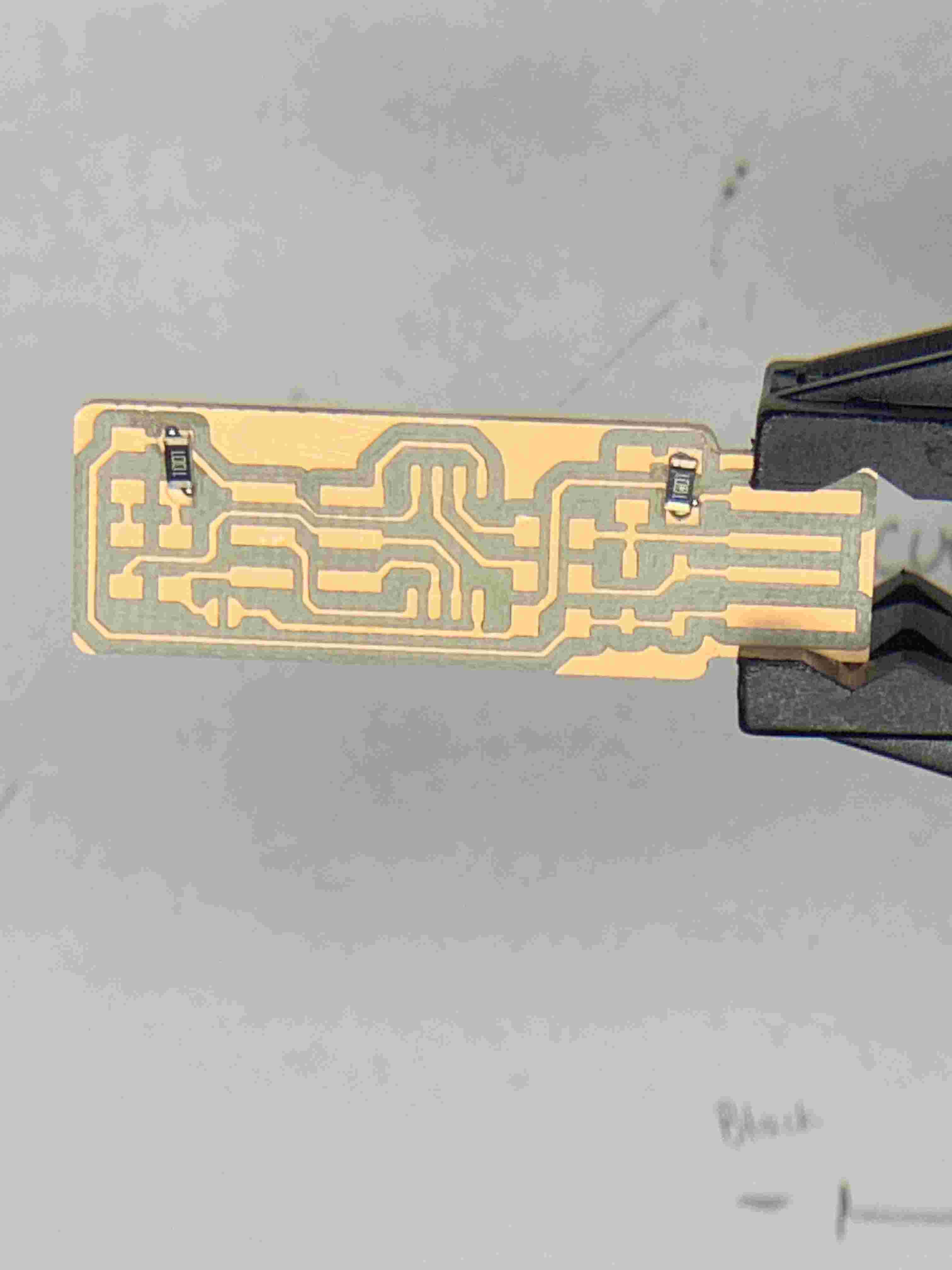
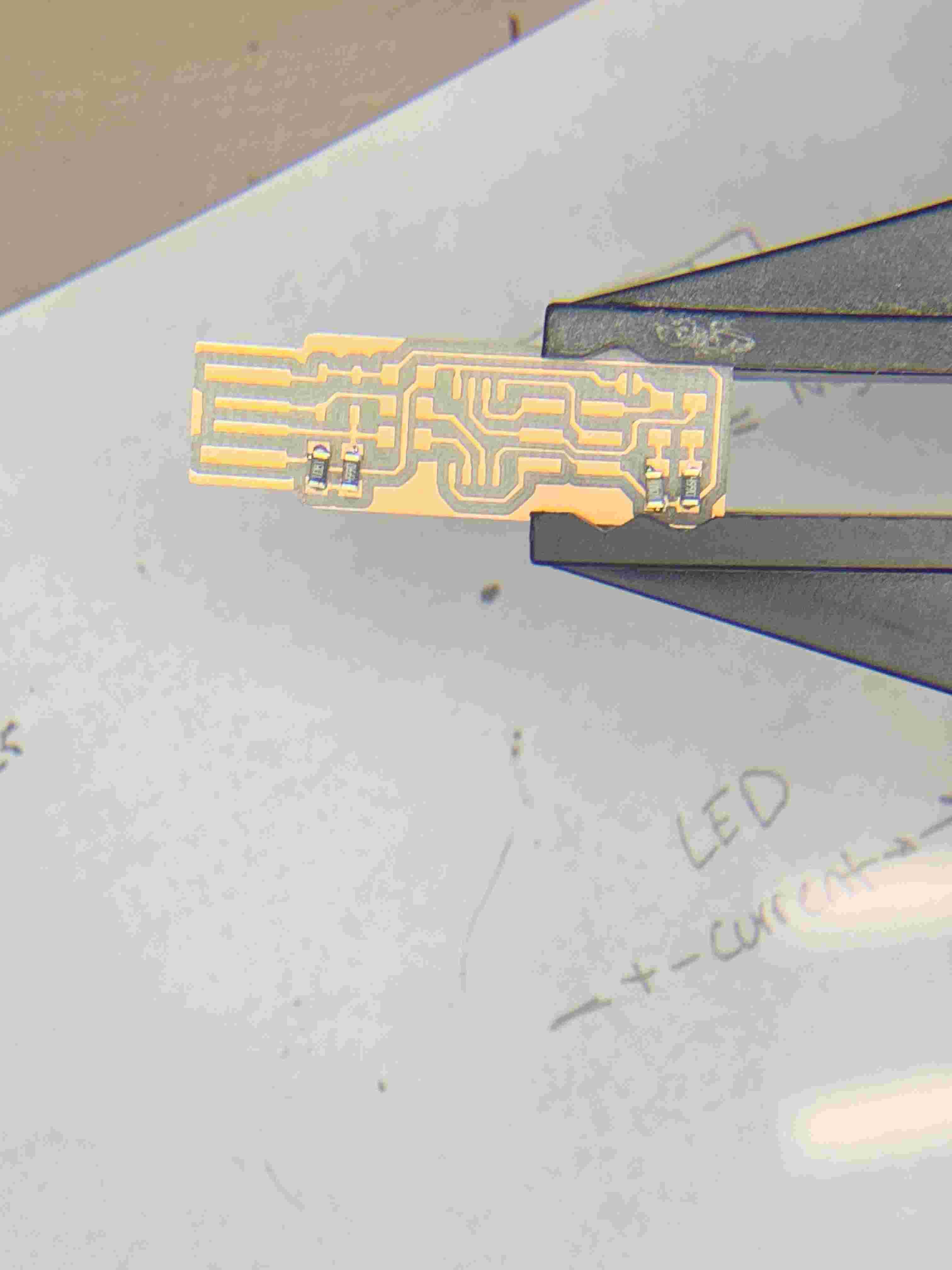
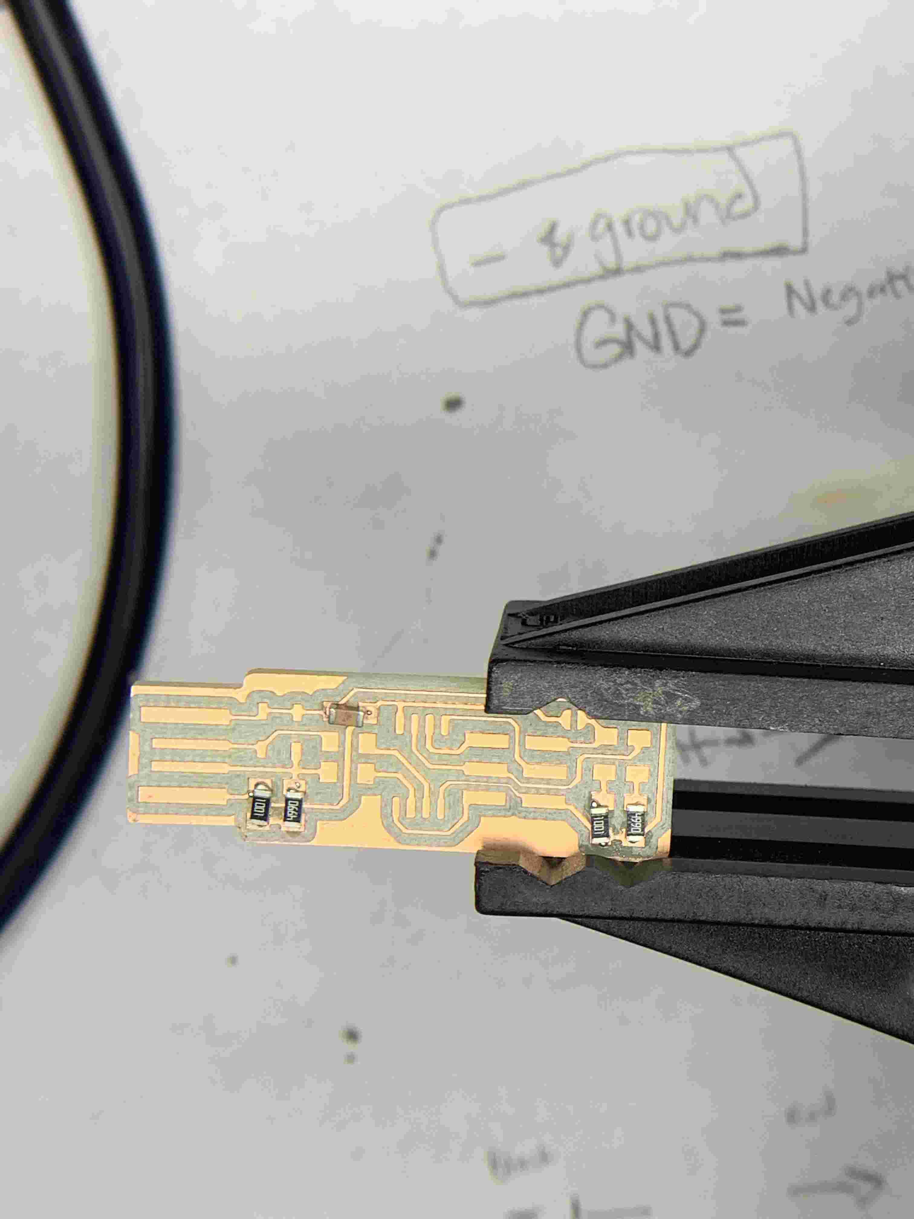
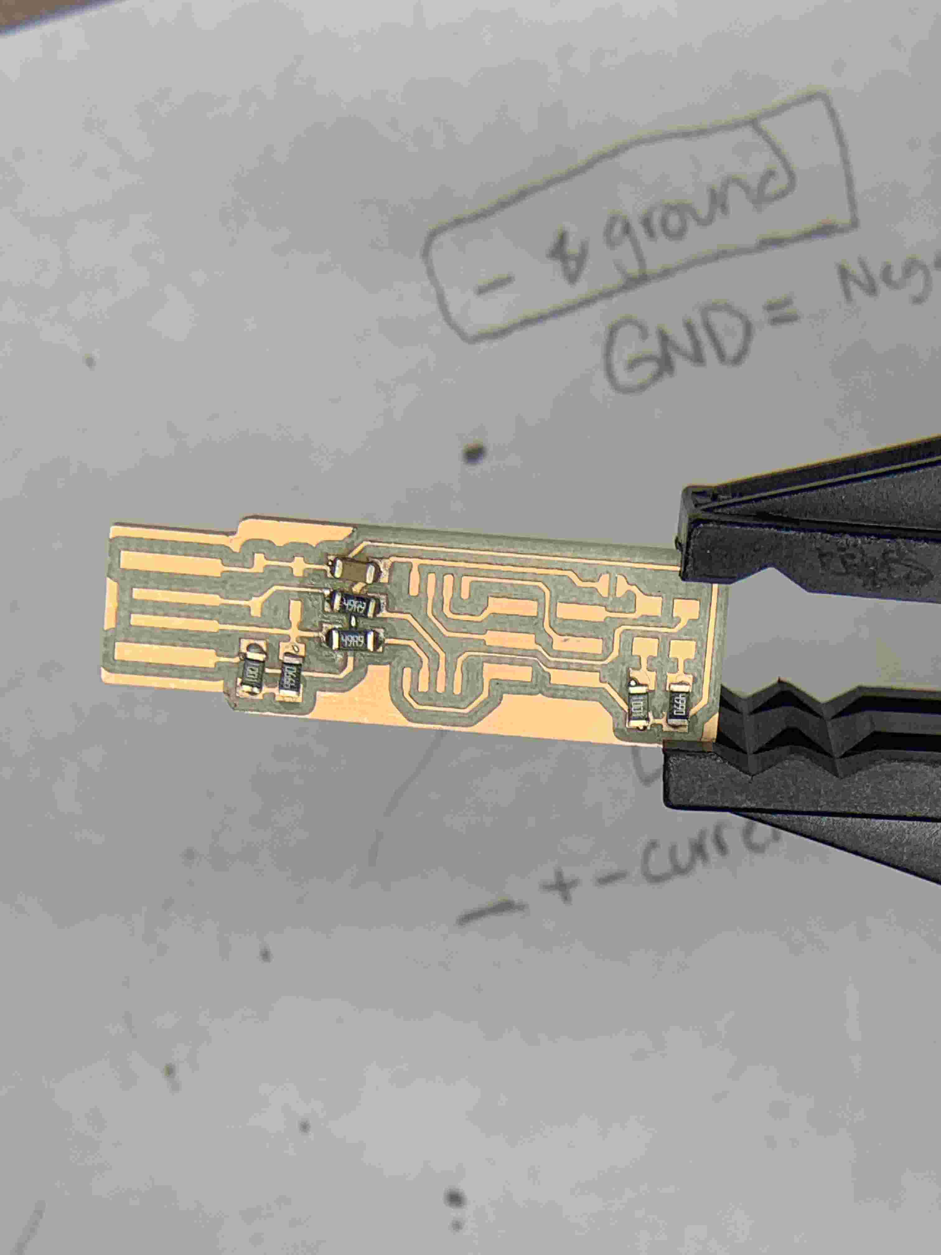
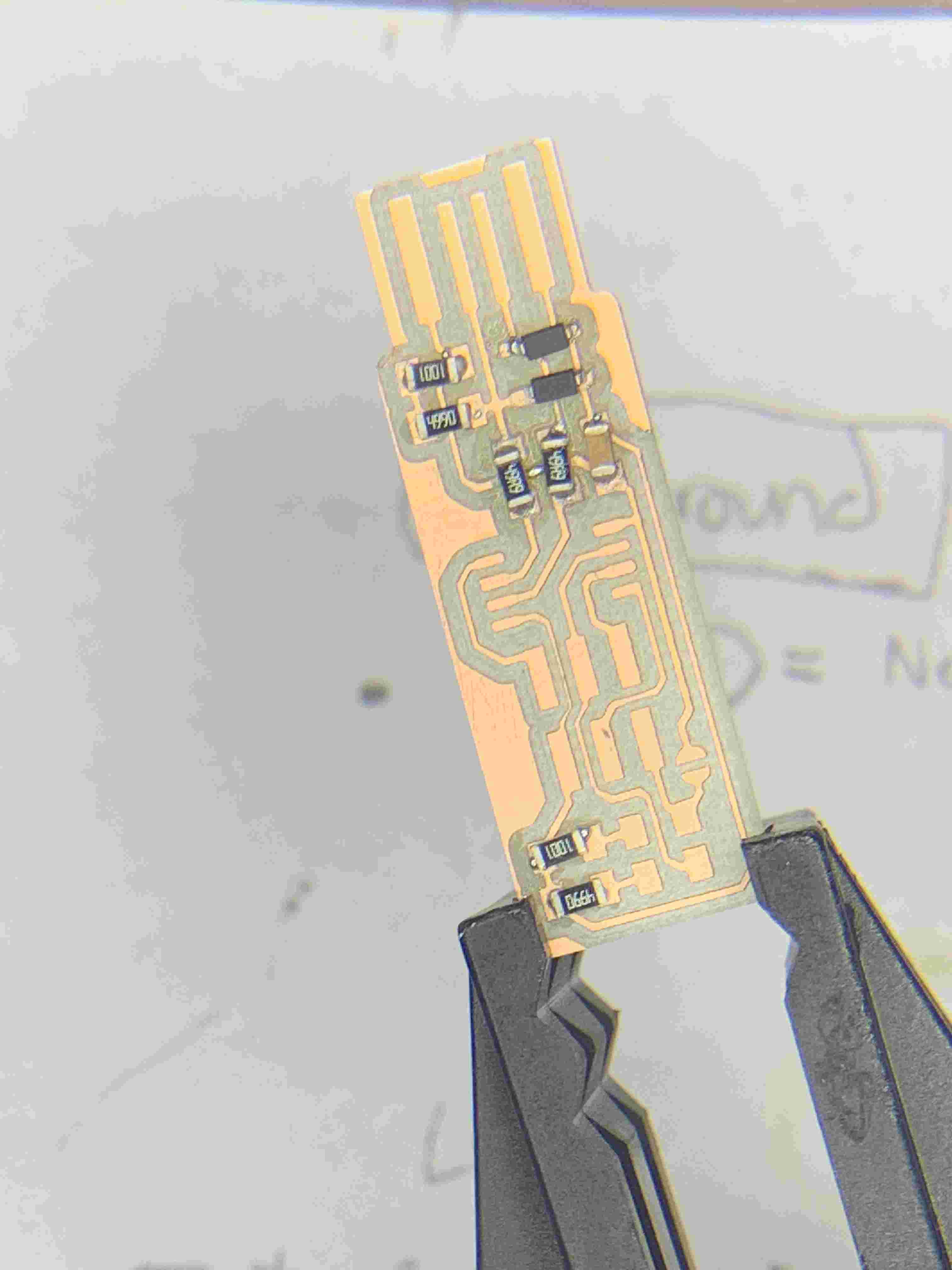
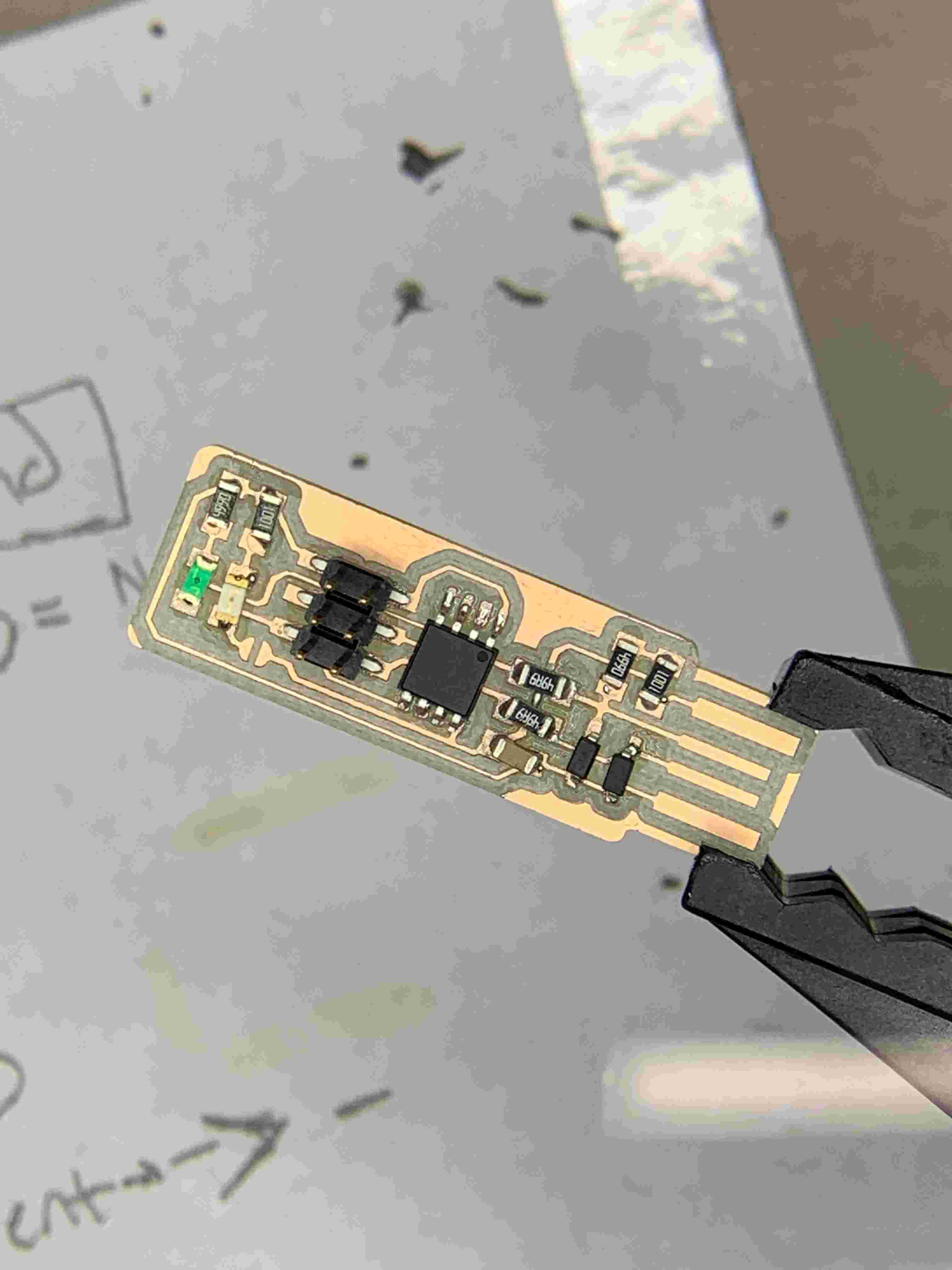
Soldering
The next step was actually soldering all of electronics to the board. I have shockingly little to say about this. It was my first time doing any soldering, but I found that it wasn't to difficult if you prepare your parts, take your time, and pay attention. Once everything was soldered I just had to program the board properly.
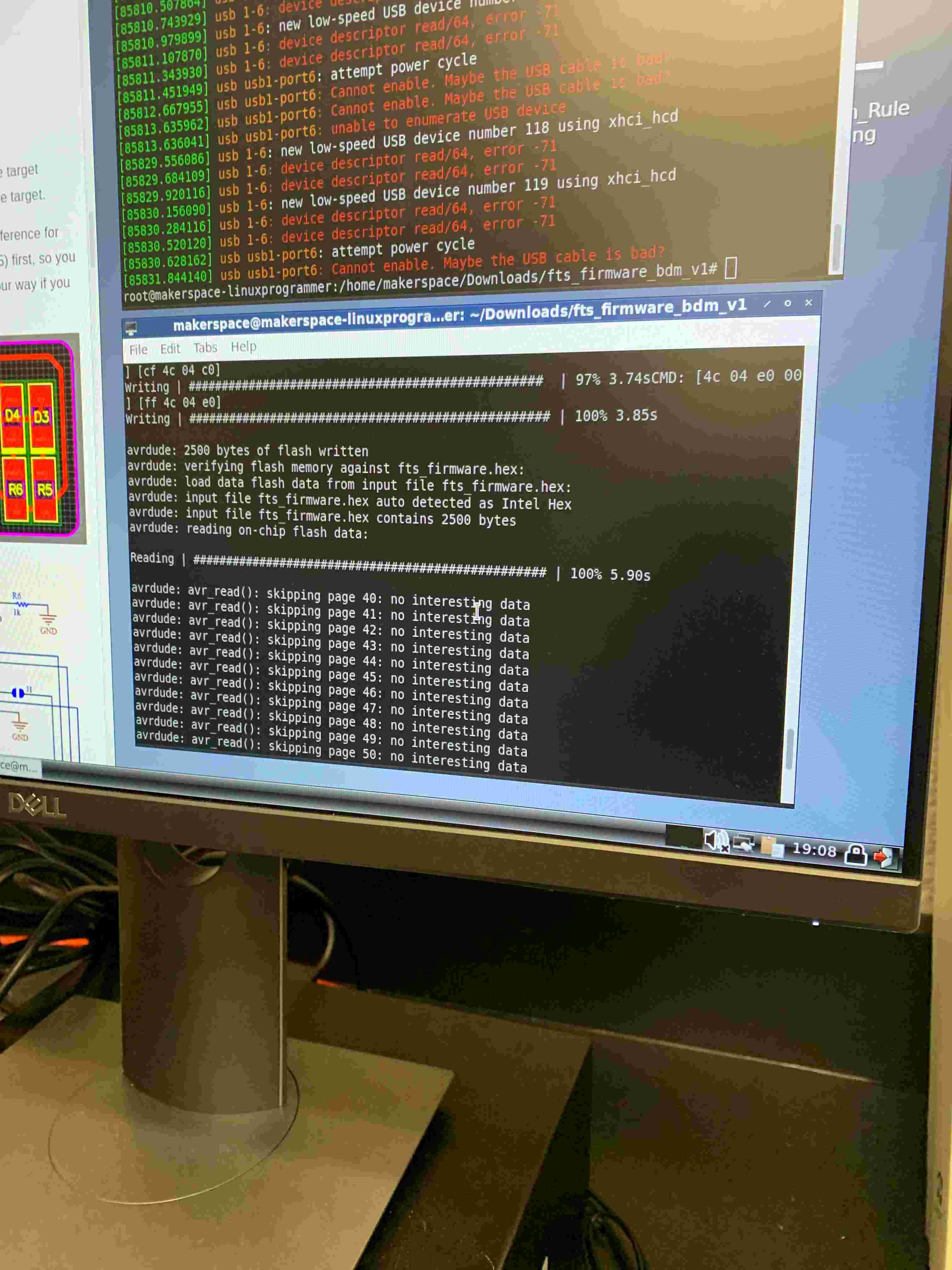
Programming
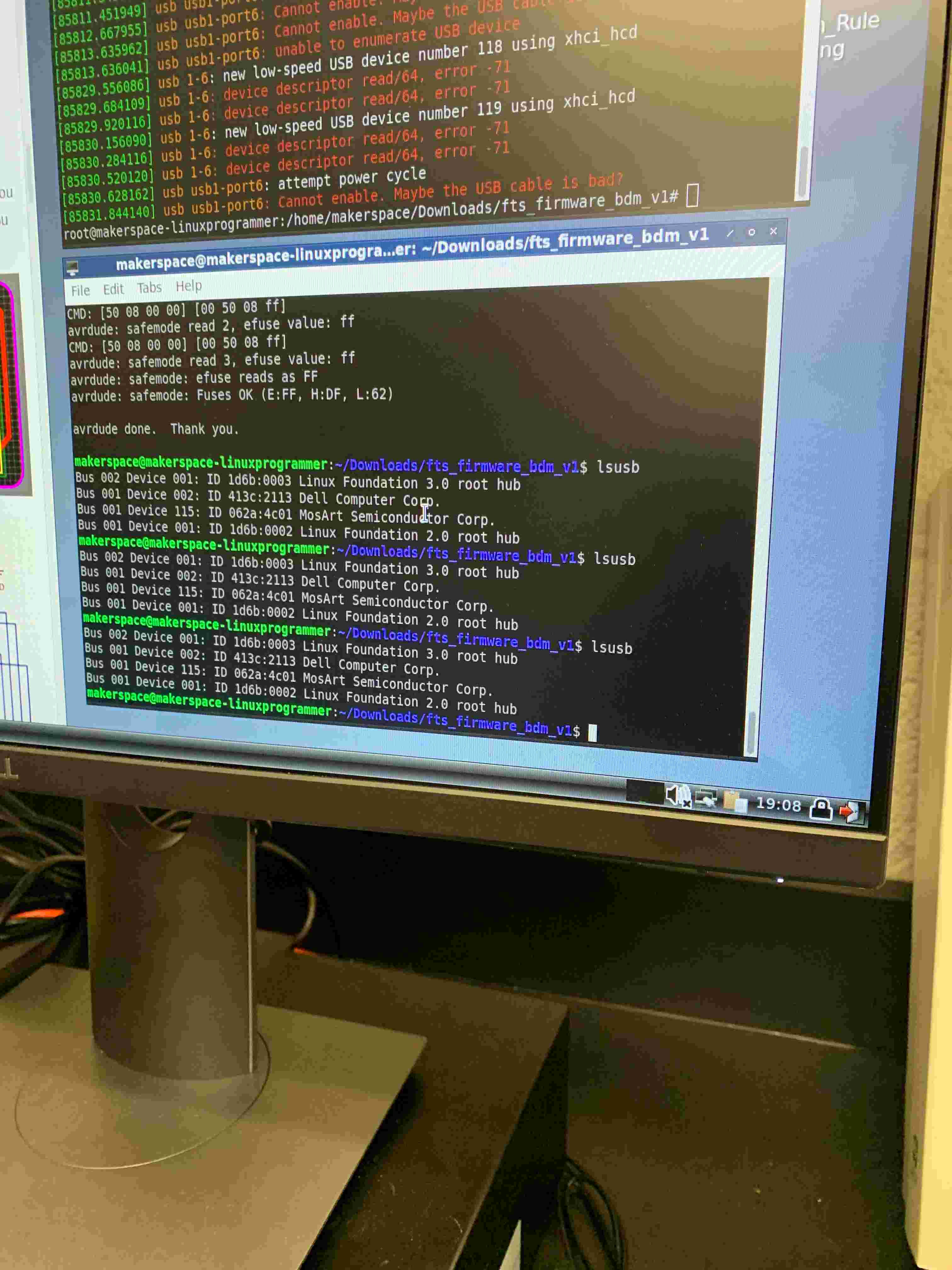
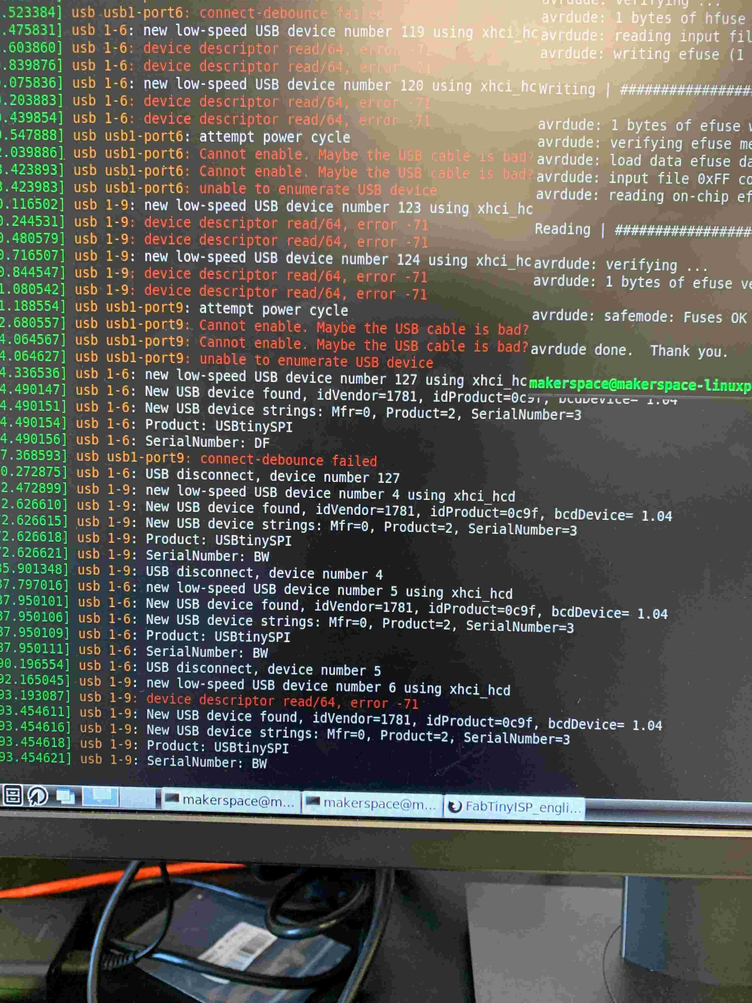
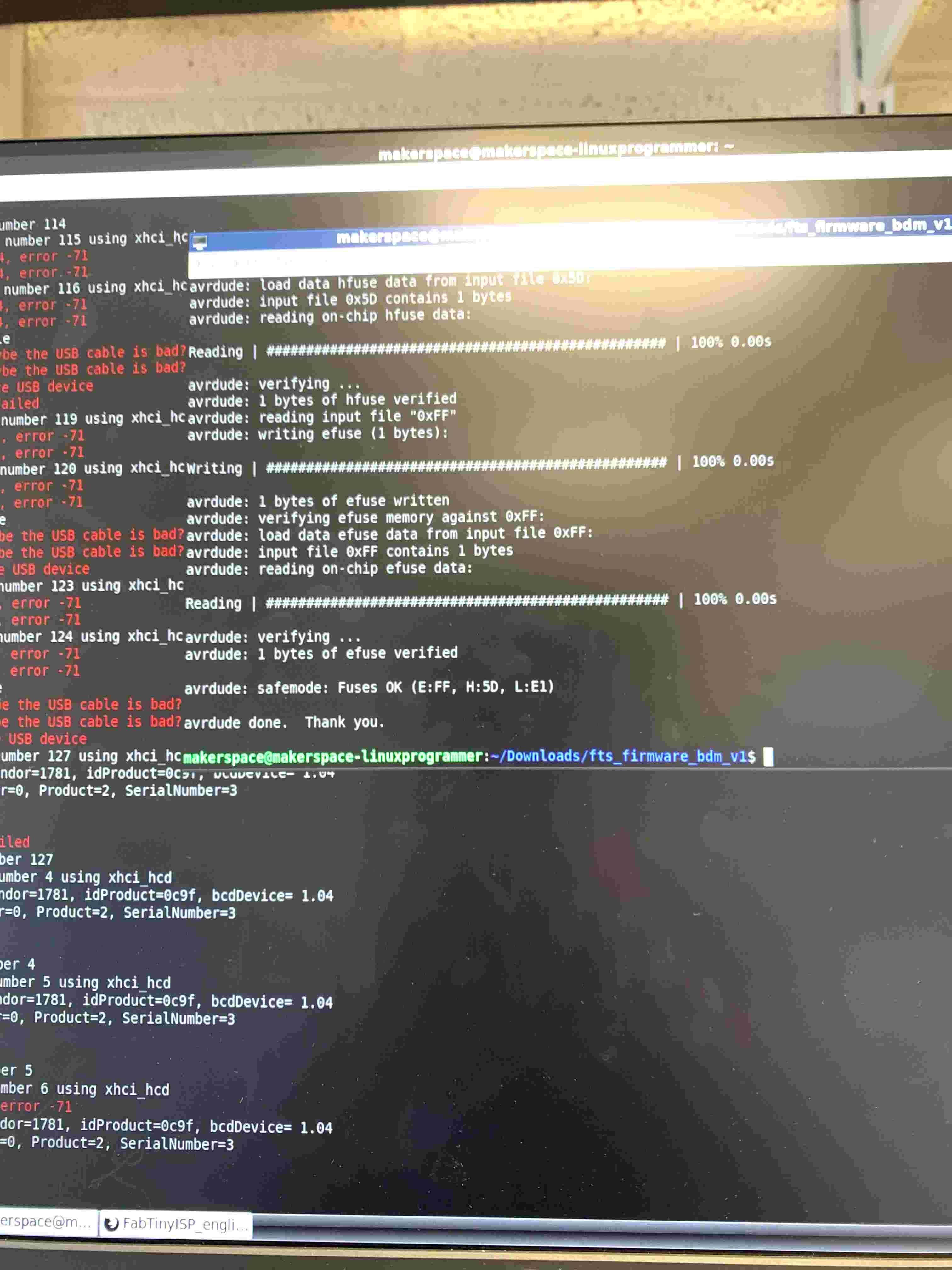
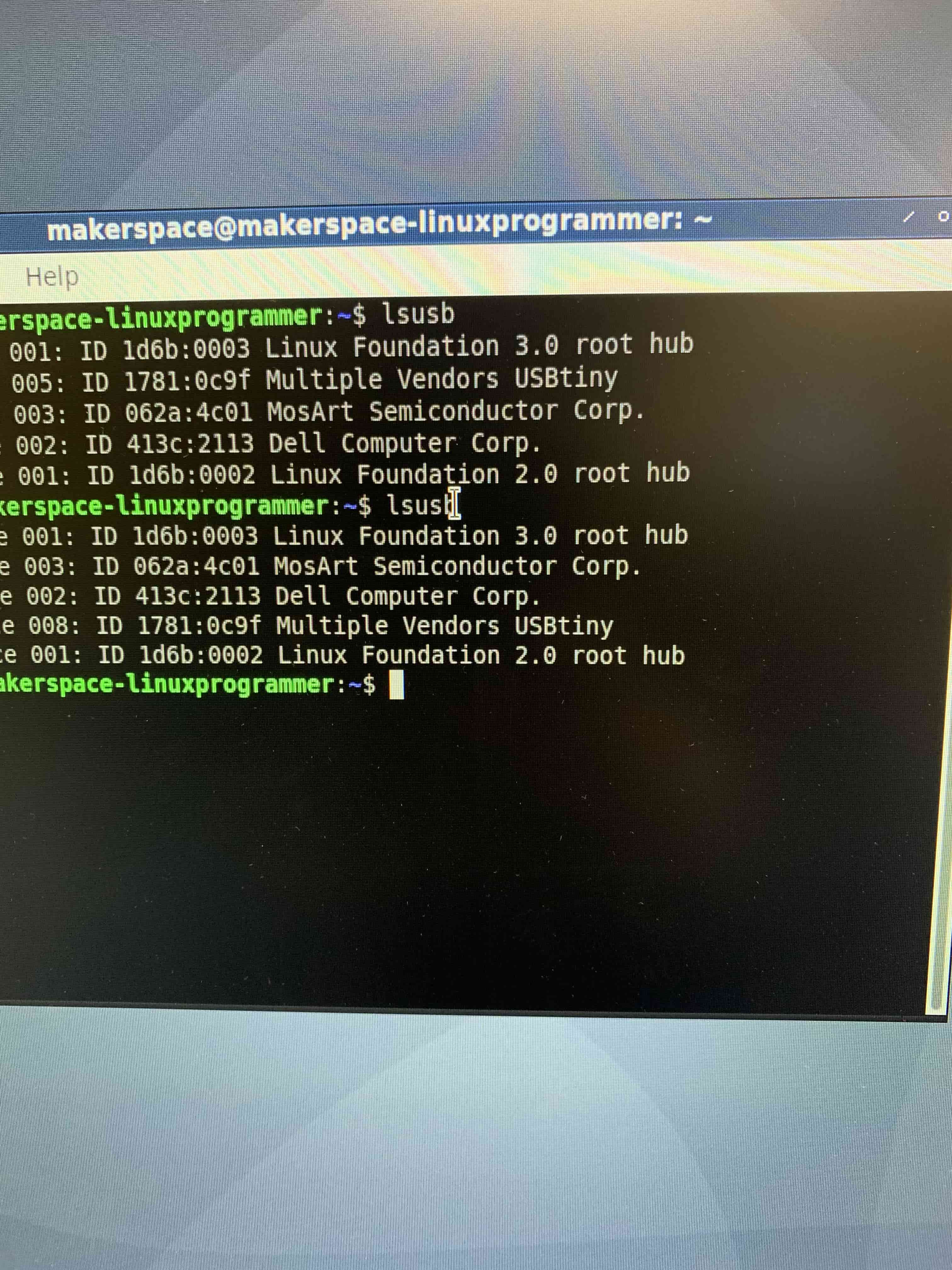
I was fortunate when programming the board that we have a linux machine set up in the lab so that it really wasn't that difficult a process at all. The first thing I needed to do was edit the makefile for the programmer to set it to be programmed by an ATtiny. I then needed to run make flash, and the make fuses. Once I did that and saw the my ubs device was viewable, I then ran the make rstdisbl command. The last thing I did was break the jumper on the board, and I was done!
If you would like to download the files that I used you can click this button.