 Equation for spindal speed
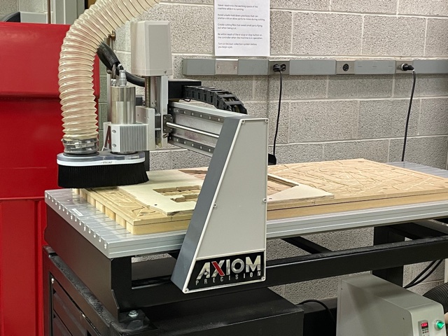
We began this week by looking into our Axiom CNC that we had here at the Wheaton FabLab. We first wanted to look into some of the specifications that our specific machine had. This included looking into the feed rate, spindle speed, and other such values.
 Equation for spindal speed
We first went about this by designing a small little cut in the vCard software, I mainly know how to use 3 axis machining with the tools used in Fusion 360 so the specifics of vCard will not be elaborated on here.
 Equation for spindal speed
The first design that we wanted to cut out was a 2"x4" rectangle so that we could test how truly it would cut to this design. With a little bit of intuition, we know that our expected value should be equal to the side of the rectangle minus the diameter of the bit.
On another note, the Axiom performed smoothly. With a machine this big it is important for us as students to be careful and always make sure that our equipment is running smoothly with the correct settings, which in this case, seemed to be good.
 Equation for spindal speed
 Equation for spindal speed
You can see that the dimensions we got for our cut ended up being 1.779"x3.774". Given that the diameter of our bit is about 0.25” we should expect our values to be around 1.75”x3.75”. The experimental values we got were around this number although a little larger which should be fine for the time being.
 Equation for spindal speed
The second cut we designed was one where we drilled our .25 inch diameter drill bit into the wood so that we could measure what the experimental result of that would be. When we did this, we calculated the diameter of the hole to be around 0.2395 inches, which is just a little off from the expected value of 0.25 inches.
Above is the assambley of the design that I was aiming to create. I thought it would be cool to create my own little model plane set for this unit.
 Equation for spindal speed
I first went about sketching out my designs. There was a total of eleven designs that I needed to sketch out all while making sure that everything would fit together in the end
 Equation for spindal speed
Next I went about extruding those pieces to about 0.5 inches. This was the thickness of the boards that we were using so the final thickness of everything would come out at that specification.
 Equation for spindal speed
Above is all the designs that I needed, and now I would drag each one out of this menu into one assembly so that I could start the manufacturing process.
 Equation for spindal speed
Above you can see the start of this process.
 Equation for spindal speed
Above is all of the eleven components that were added into my design. Below you can see them organized within the confines of the board which is about 2ft x 4ft
 Equation for spindal speed
The bar above in the manufacturing tab of the Fusion 360 shows many of the 2 axis, 3 axis, and multi axis options that we have at our disposal within the CAM software. Also along this bar are options to set up our manufacturing, as well as post processing.
 Equation for spindal speed
The first thing we will want to do is to select the setup option on that top bar.
 Equation for spindal speed
With this we will want to create the dimensions of the stock that we will be cutting into as well as making sure that the origin is in line with what is set up on our machine. In this case I set up the origin in this orientation as That is what it programmed into our CNC Axiom.
 Equation for spindal speed
 Equation for spindal speed
The two main pathing tools we will be using in this build is 2D Pocket and 2D Contour. The 2D pocket will be used to cut any holes, this goes for holes that do not go all the way through the material as well which are integrated into my design. I will use the 2D contour to create paths to cut out the lareg objects in my build.
 Equation for spindal speed
Above I am creating the path for my 2D pockets as I have all the pockets that I want to create selected in my design.
 Equation for spindal speed
With in the settings for 2D pocket we need to make sure that multiple depths is selected and that the roughing stepdown is a good value.
 Equation for spindal speed
Here, I am selecting the bottom lines on my design that will trace out the path for my 2D contour. It is also imperative that I have tabs selected on this screen as we will need the pieces to stay in place so they are not thrown into the air by the Axiom.
 Equation for spindal speed
Again we need to make sure that mutiple depths is selected again.
 Equation for spindal speed
Finally we can see a simulation of all of our cuts together.
 Equation for spindal speed
One problem I had when I first used the Axiom was that when I started my file the drill bit went to far down in the wood causing which made a couple of burn marks, I even had multiple depths selected so I had no idea why my file failed. Later, after conversing with a couple of fellow students I found our that this problem was ocurring because of the units not being the same across all of my files.
 Equation for spindal speed
Here I went to my files and made sure that everything was set to inches instead of millimeters.
 Equation for spindal speed
Before using the CNC Axiom you will need to check this panel to make sure that it is powered on. As you can see the green switch is turned to the right which means that the power is on.
 Equation for spindal speed
This is the main control panel that is used to control the CNC Axiom, The are a number of buttons below but we will first take a look at the screen. As you can see we have a screen that initially shows us our current x, y, and z positions which can be very important to see. the screen will also allow us to navigate through plenty of different menus.
 Equation for spindal speed
Below the screen we have numerous buttons that will allow us to manually move the Axiom drill head as well as things like zeroing our x, y, and z axis. The green 'run' button will allow us to run our programs while the red 'stop' button will allow us to cancel programs, while Axiom is running we have been told to keep our finger on the stop button at all times.
 Equation for spindal speed
This is the drill bit with the broom taken off, as mention before it has a diameter of about .25 inches.
 Equation for spindal speed
To secure the piece of wood that we are cutting, not only will we line one side with double sided tape, it is also important to drill each corner of the wood into the spoil board so that it can remain in place.
 Equation for spindal speed
Next, using the control panel, we will use the buttons to move the drill bit to where we want our x and y to be zeroed. once int he desired position, we will press the yellow XY -> 0 button.
 Equation for spindal speed
To zero the z axis, the process is similar, but we will make use of the tool above which will automatically zero the z axis for us. All we need to do is position the tool under the drill bit, which will then slowly lower to lower until it maked contact which will also then zero the z axis.
The final thing to do before running any toolpath is to turn on the sawdust collector, also it might be a very good idea to wear earplugs as well, but you must make sure you can hear if anything goes wrong.
 Equation for spindal speed
I never finished milling my original design because I got a little scared of using the Axiom after my cut failed the first time, I was being a little sheepish because I really didn't know exactly what I was doing and didn't want to break anything. But later, David and I worked on finishing the Ballista that he prototyped.
you can check out his original week on this. Mainly we made it bigger and studier, and reinforced with some wood that we cut with the table saw. Below you can see us test firing it and we are glad that it finally works.