Our machine is the Prusa i3 Mk3s which we used during the tests that we undertook. In our group assignment, we were tasked with testing the design rules for our printer. To achieve this we found an all in one 3D printer test kit that allowed us to do a stringing test, a sharp corners test, a scale test, a tolerance test, a bridging test, and a overhang test.
 The Prusa i3 Mk3s
Some more info about our printer:
 Equation for spindal speed
 Equation for spindal speed
Overhang Test: As we can see from the pictures above once we hit around 50% the quality of the print decreases.
 Equation for spindal speed
Sharp Corners Test: The sharp corners that were supposed to be printed of ended up not being very sharp at all. This shows us that our printer isn't the best at printing finer details
Bridging Test: The columns on the bridge actually came out nice, but on our longest one, the connection to the supporting beam is not very good at all. Our printer can print off beems but we should not do anything to long with out putting on extra supports.
Tolerance Test: Our printer could print grooves out nicely, only really failing on the smallest groove. On the other hand, the Prusa did not do well printing off smaller lines as it was only able to make two of them.
Stringing Test: There was a little bit of stringing, but for the most part it printed out well. Though we can deffinetly see some string residue left over where it stopped printing in some areas.
 Equation for spindal speed
Another Test we did was the Benchy with the MMU2 so we could test to see how well our printer does with designs with multiple filaments. This print came out extremley well with only minor impurities, although it did not print the roof of the ship which was a little perplexing. The downside to this is that we didn't get to how it would hand overhang with different filaments.
Additive vs subtractive manufacturing:
 Equation for spindal speed
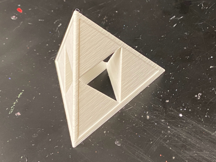
My idea was to make an interesting shape that would be very hard or impossible to make with subtractive manufacturing. So to start, as can be seen above, I started out by making a tetrahedron.
Above you can see my final design as seen in Fusion 360. I was influenced by sierpinski tetrahedrons and the Legend of Zelda.
This type of design would be extremley hard to make in subtractive manufacturing. Because of the geometry of this piece, milling this out would be extremely difficult even with a 3-axis machine. 3D printing machines are very useful in this regard as we can easily print and prototype different parts.
 Equation for spindal speed
 Equation for spindal speed
 Equation for spindal speed
As you can see in the picture above, I used supports within the tetrahedron so that the printing came out smoothly. Even with the supports the top of the inside is still very rough on one side.
 Equation for spindal speed
This is the finished product of my design.
For scanning my 3D object I used a software called Agisoft Metashape. This software allows you to take multiple photos of an object and render it into a 3D object. Photos work best when you take them in strips circling your object.
 Equation for spindal speed
In the workspace, we need to right click on Chunk select the file that we have all of our photos stored in. Likewise, you can also import a video and take frames from that.
 Equation for spindal speed
Next, again right clicking on our Chunk, we now go to process, then Align Photos.
 Equation for spindal speed
We want to start by aligning our photos in low accuracy, as Metashape will focus too much on the foreground and backround instead of our object.
 Equation for spindal speed
We want to create a mask on certain key frames for our cameras. We do this by double clicking on an image, then you right click, select intelligent scissors, and outline the our object. Once the object is outlined we right click again and select add selection. If mask selects the wrong area, you can right click and select invert mask.
 Equation for spindal speed
Now that we created masks, we want to realign our cameras now at a higher quality. Below you can mess with the settings but you want "Apply Masks to: Tie Points"
 Equation for spindal speed
Once cameras are realigned, we want to go back to process and run build dense cloud, build mesh, and build texture in that order.
 Equation for spindal speed
 Equation for spindal speed
This ended up being a very long process. I tried multiple different onjects, and since my camera was not very good, my images refused to align at a high accuracy. Below is one failed atempt where a majority of my images could not align
 Equation for spindal speed
I ended getting it working in the end, though I sacrificed some quality so that I could finish the render in faster amount of time. The render did come out very nice, but my computer does not have the processing power to run Metashape to its potential.
 Equation for spindal speed
 Equation for spindal speed
STL Files
3D Scan Files