For the group assignment this week, we used multimeters and the oscilloscope to observe the behavior of both voltage and current of a DC motor.
We measured both when the motor was running freely and when it was under load to compare.
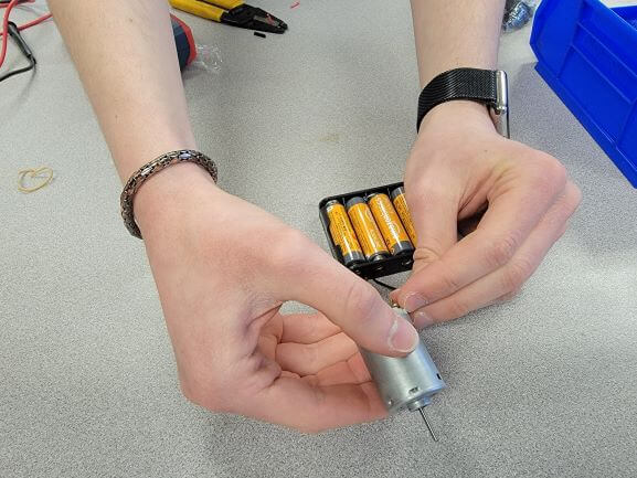
The DC motor was rated at 6 V, so 4 AA batteries worked perfectly to power it. The hardest part was having enough hands to hold the motor, wires, and multimeter probes!
We also used an Arduino and LEDs to learn about Pulse-Width Modulation and analogRead() and analogWrite().
Here is our group measuring the voltage and current when the motor is being held. Between measuring, holding the circuit, stopping the motor, and filming, this was a 5-person job!
You can here us say "voltage dropped down to 5" and "amperage went up to almost 1 Amp."
We found that while running free without being loaded, the DC motor ran at 6.1 V and 0.1 A.
When being held from spinning, the DC motor ran at 5 V and just about 1 A.
We learned that Wattage = Voltage * Current, so our motor takes a maximum of 5 V * 1 A = 5 Watts while under a full-load.
But, the ATtiny is only capable of outputting about 40 mA per pin! So, we have to use transistors to manage the flow from an outside power-source to the device to power.
We then learned about Arduino's ability to output PWM signals on its pins.
This means that the pins send alternating high and low pulses to rapidly turn the device on and off faster than we can detect.
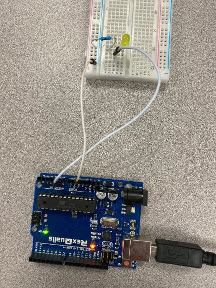
For the lab purposes, we dimmed and brightened an LED using PWM and analogWrite().
As the value inside of analogWrite decreased, the LED dimmed and as it increased, the brightness increased too.
Here is a video of our class observing the PWM signal on an oscilliscope.
Notice how the LED is brighter when the pulses are more frequent. This is because it is flashing much faster.
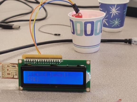
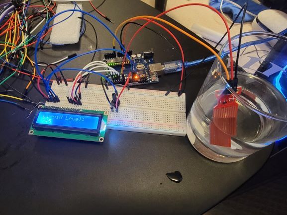
Now, for the individual assignment, I wanted to make something that could potentially be used on my final project of a Smart Bar. So, I decided to use a liquid level sensor along with an LCD screen to display the current level of liquid in a cup.
It's a little tough to pick up the screen on-camera, so I apologize that you can't really read the text. But it says "Liquid Level: FULL"
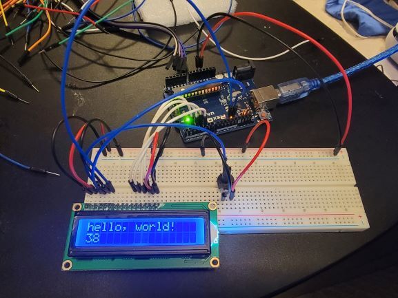
I found an amazing tutorial for using the 16x2 LCD screen with an Arduino and followed the tutorial exactly. This worked perfectly!
The screen displays the message "hello, world" as well as the number of seconds the device has been powered on for.
I also learned that this particular display can only show 16 characters on 2 lines for a total of 32 characters.
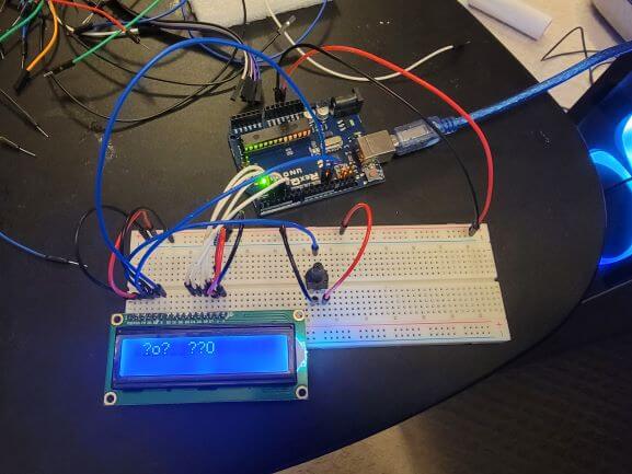
And here's the screen working with an Arduino Uno.
I used the only potentiometer that I had in my electronics kit for the screen contrast adjuster, but switched this out later. We'll get to that.
If a wire comes loose, or the screen is unplugged and plugged back in without resetting the Arduino, this happens.
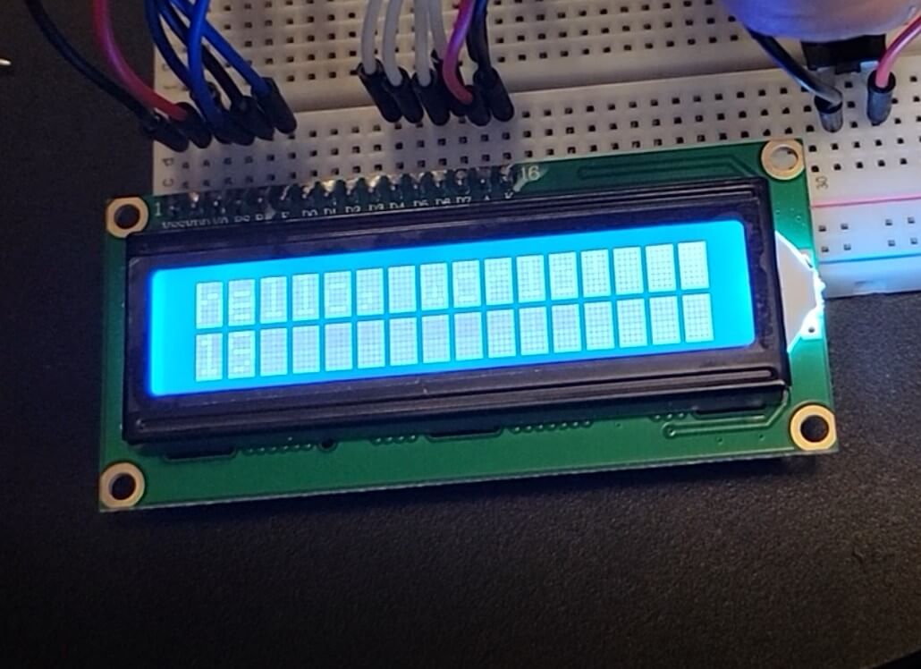
And here's what it looks like if the contrast potentiometer is turned too high. If its too low, the screen looks blank.
I then found a tutorial about interfacing a liquid sensor with Arduino and used realized it was as simple as hooking up the sensor to an input pin and using analogRead() to get the value. The sensor also needs to be supplied 5 V and connected to Ground.
The higher the value returned by analogRead(), the more of the sensor is covered by liquid.
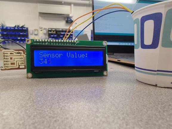
Here's the screen interfacing with the liquid sensor. The sensor is reading a value of 345. My testing has shown me that the highest value is roughly 350, but that has to be tweaked based on the liquid.
In fact, water from different sources can actually give different values because of the difference in conductive minerals between them.
Then it was time to design this circuit and mill the board!
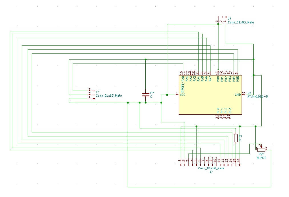
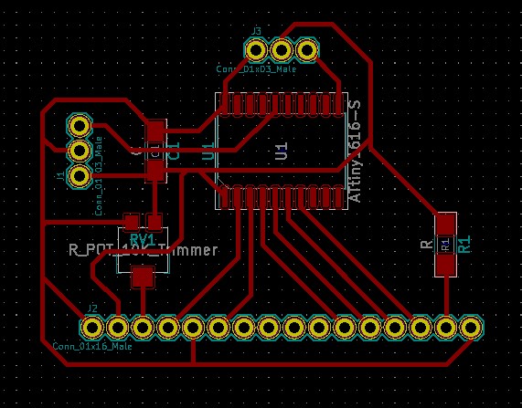
As always, I used KiCad to design the layout of the board. This time, however, I really put thought into what pins of the ATtiny connected to which pins of the screen.
The screen has 16 pins, each with a different purpose. But, the tutorial shows that we only need 6 pins out of those 16 to be connected to the microcontroller. The rest are connected to power, ground, the potentiometer, or nothing!
Knowing this, I purposely laid out the circuit in a way such that the pins of the ATtiny that need to reach a pin of the screen were on the same side of the chip as the screen.
I also added pins for the sensor. Theoretically, these pins could really be used for any input or output device depending on the code loaded on the 1616.
Here's the KiCad Schematic
And the KiCad PCB
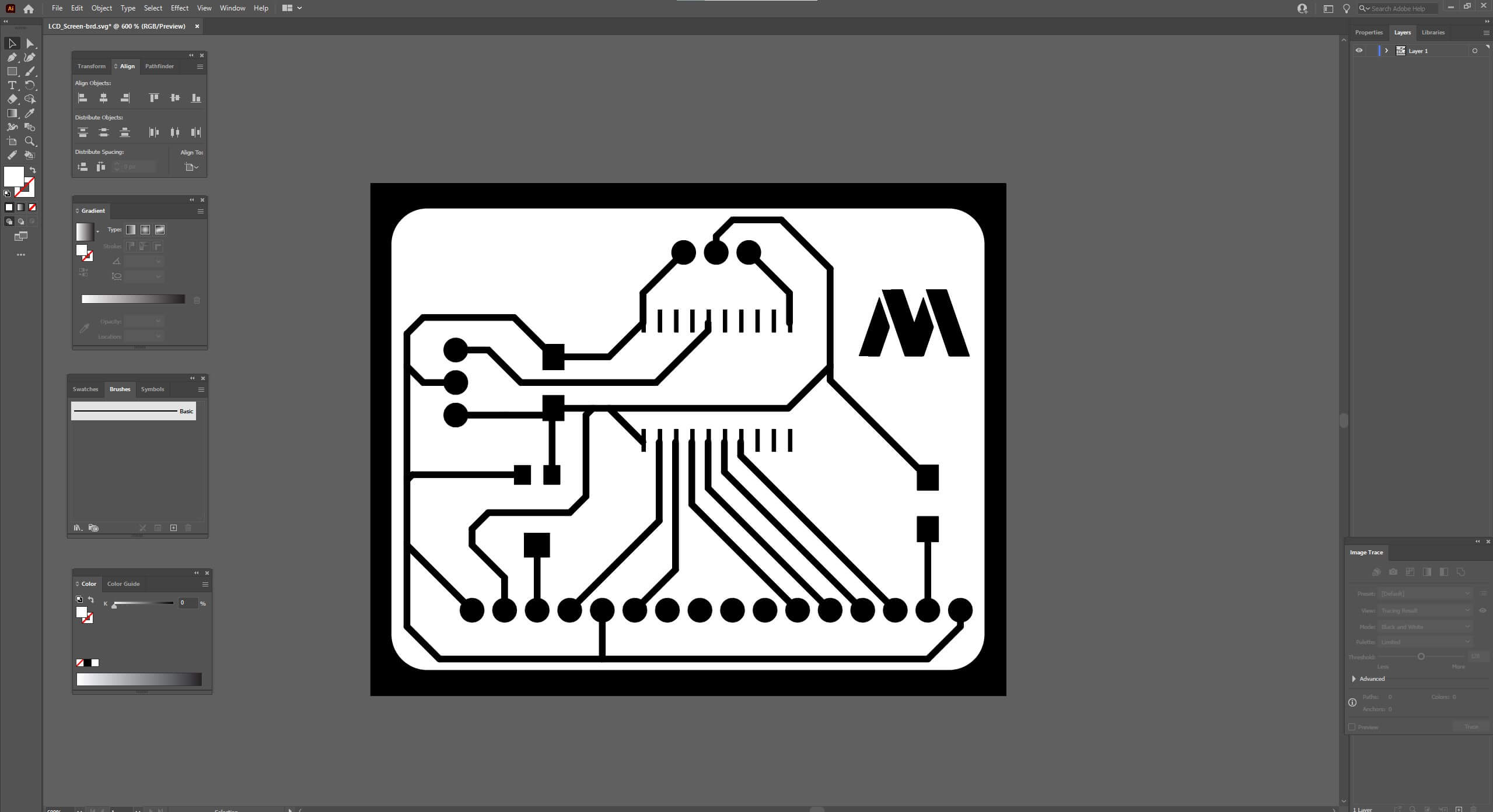
I then used illustrator to create PNGs for the traces, holes, and outlines
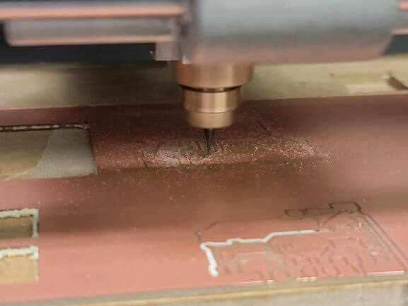
Then sent those PNGs to MODS and milled using the Roland
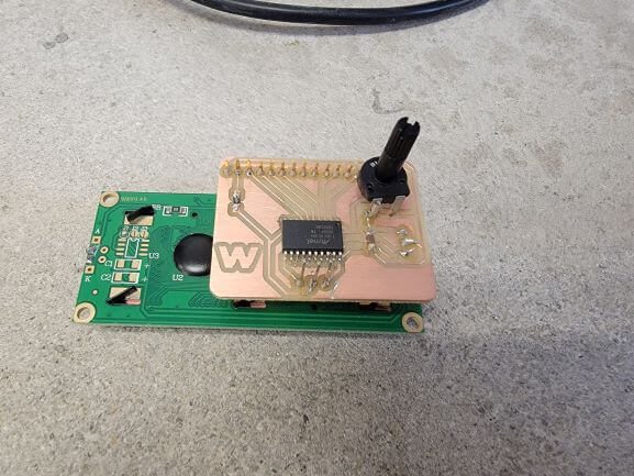
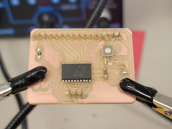
Then I soldered everything onto the board. I used female to male headers to attach the screen so that I could reuse it for something else if I chose to.
Also, notice the large potentiometer. It was much larger than the footprint I chose!
Only after soldering everything on and struggling with the large potentiometer did I realize that we actually had the correct potentiometer in the lab...
So I unsoldered the old potentiometer and soldered on the correct one. This looked much better!
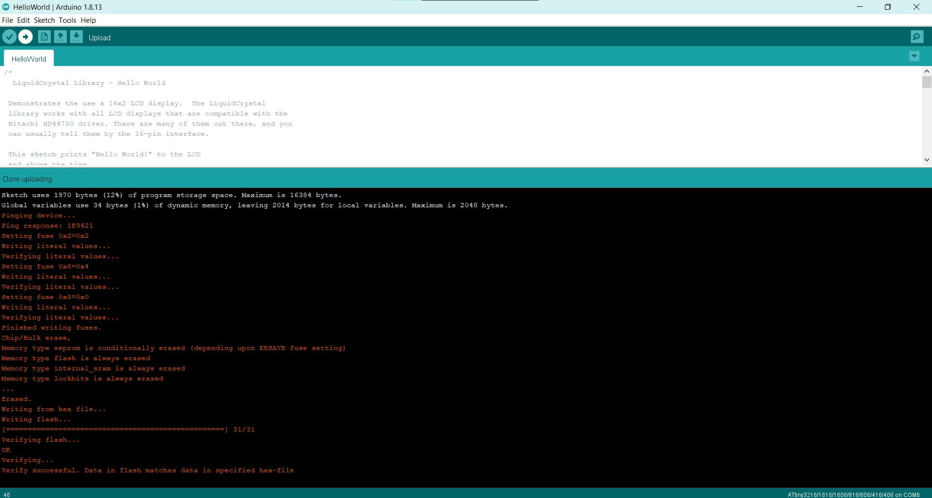
Then I edited the code from my Arduino prototype to match the correct pins of my ATtiny 1616 version.
I uploaded it using the exact same methods outlined in my previous electronics weeks. It uploaded fine without any errors.
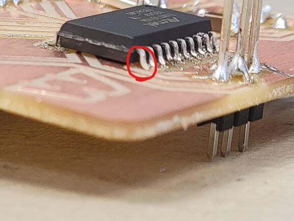
And the screen actually turned on! And it said exactly what I expected it to! Except, it was reading random values around 430 regardless of whether it was in liquid or not. I tried adding a pull-down resistor and troubleshot for half an hour before realizing it was poorly soldered at the input pin of the chip!
Here is the pin that wasn't properly soldered. I used air-solder for the chip, so maybe this pin didn't get hot enough?
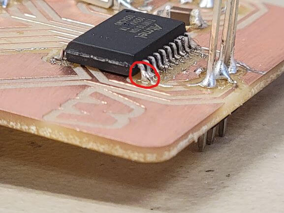
And here's the pin re-soldered.
And here's what it looked like after making this fix. It worked!
After I was confident it was working, I ran some tests to find which sensor values corresponded to which fill-values.
Raw Sensor Value and Fill-Level:
Less Than 100 = EMPTY
Between 100 and 200 = LOW
Between 200 and 340 = MEDIUM
Greater Than 340 = FULL
These values are not totally accurate because sometimes the sensor will read LOW when it is actually out of liquid and drying.
I also ran into the issue of clearing the screen. You cannot clear just one line at a time and if you don't clear between rewrites, the characters that are not overwritten will remain on the screen.
That means that if it went from MEDIUM to FULL, the first 4 characters of MEDIUM would be overwritten, but the fill-level would still read FULLUM beacause the U and the M of MEDIUM were not overwritten.
But, after all these tweaks, my device ran beautifully and I may actually use a couple of these for my final project!