For the group assignment this week, our class broke into our usual teams and tested a few input devices with a multimeter to observe their behavior.
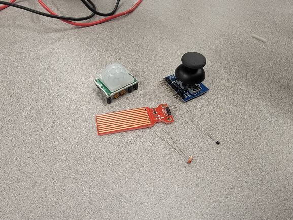
We tested a PIR Sensor, Analog Joystick, Touch Sensor, Thermistor, and Photoresistor.
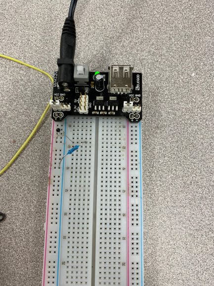
This is the circuit we used to test all of the input devices.
The black board is plugged into a wall outlet and supplies 5V to the breadboard. The resistor simulated a step-down resistor but also made it easier to measure the voltage.
The black piece that looks like a resistor is a thermistor: a resistor that changes resistance with heat. This was swapped with different input devices for each test.
Here is our circuit with the PIR Sensor. Watch as the voltage changes when we wave our hand above the sensor.
This behavior was consitant for all the sensors we tested. As we interacted with the sensors, the voltage changed depending on what we were doing.
The next half of lab was spent individually working in TinkerCAD Circuits to simulate the use of input devices with an Arduino.
This is when I deciced to make a 'Social Distance Enforcer'. The goal of my device is to sound an alarm when an individual is less than 6 feet away from an ultrasonic distance sensor.
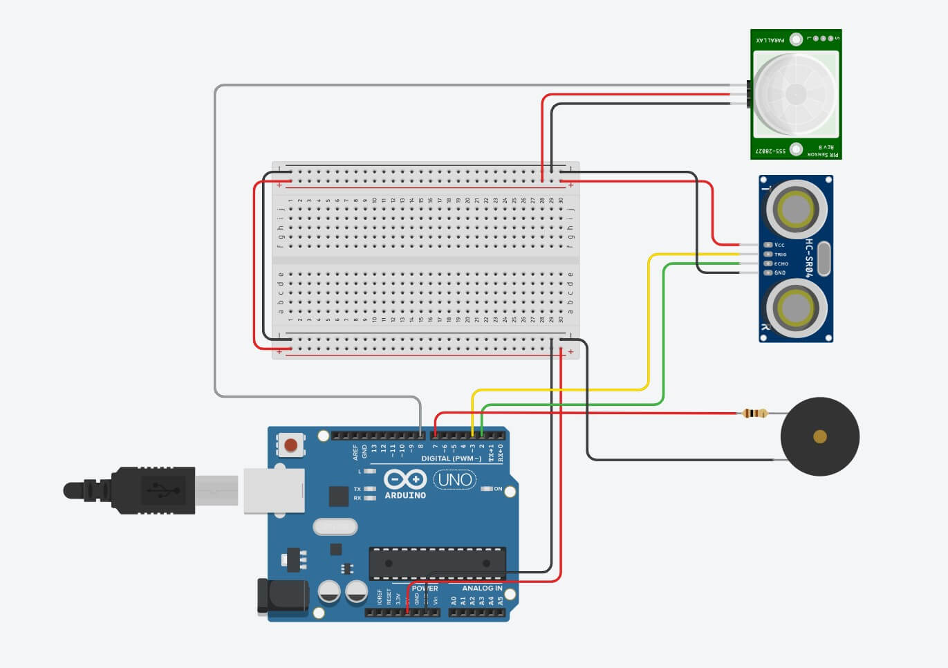
After I had this working, I added a PIR sensor to the circuit so that the buzzer would only activate when it dectected motion less than 6 feet away
And I wrote the code to allow it to function. There were still some things I had to work out, but I saved that for the final physical board
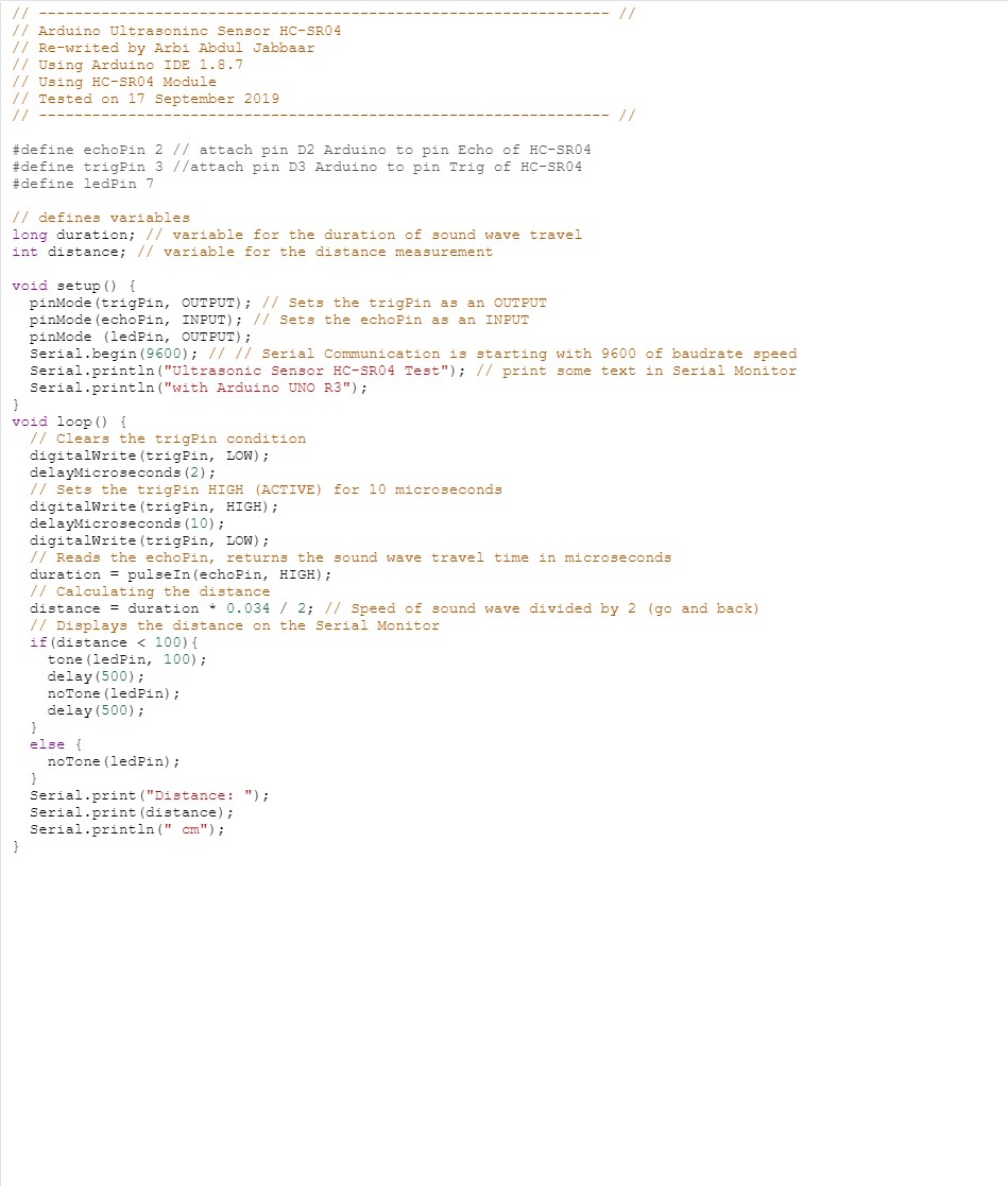
I used code from an online tutorial by Arbi Abdul Jabbaar that calculates distance in cm using an Arduino and the utrasonic sensor.
I editied the code to trigger the alarm when the distance was less than a specified value. This value is a variable and can be changed to support any distance up to the max range of the ultrasonic sensor (about 13 feet).
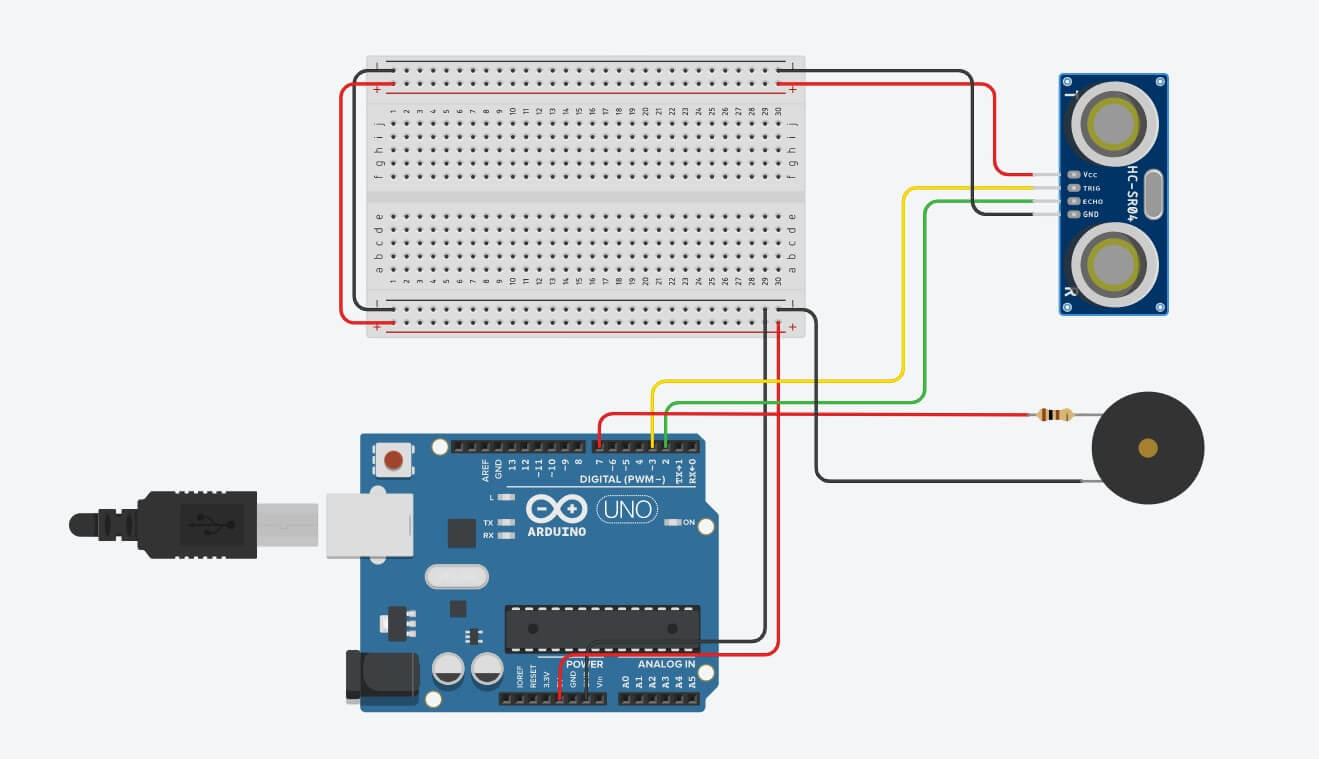
I then built the circuit just using the distance sensor to test the accuracy.
In this code, the alarm is set to sound when anything gets less than 10 cm away. The alarm stated to sound just under 11 cm away. Not bad!
I also forgot to take a video of it, but I did test from 6 feet away, and it still worked!
After taking this video, I attempted to add an HC-SR501 PIR Sensor.
It seemed to work at first, but later stopped working. I thought I had a faulty device but I tried a different one from Wheaton and still couldn't get it to work.
It was strange because the multimeter showed a voltage when the sensor detected movement, but the Arduino would never show a signal on it's pin.
I decided to incorporate the PIR sensor into my design still, just in case it was the Arduino's fault.
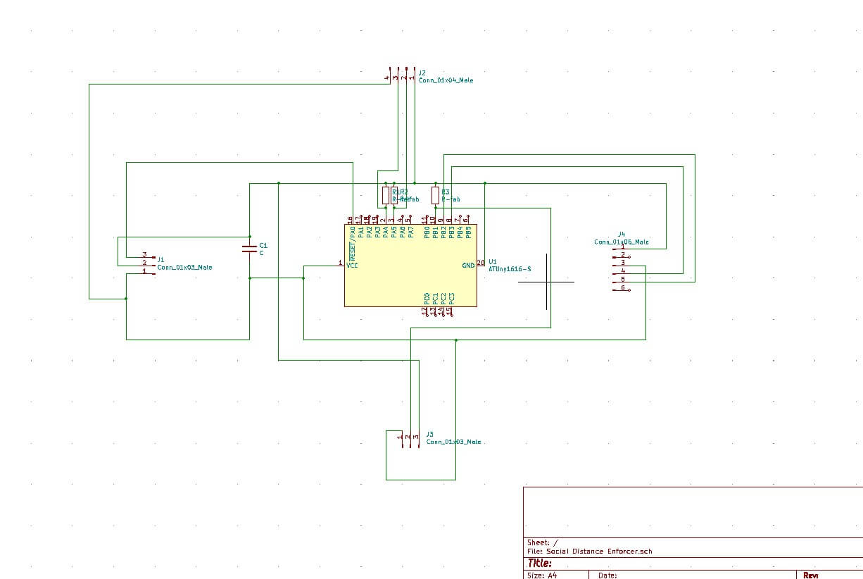
I chose an ATtiny1616 as my microprocessor because I am familiar with it and I know my computer supports programming it without issue.
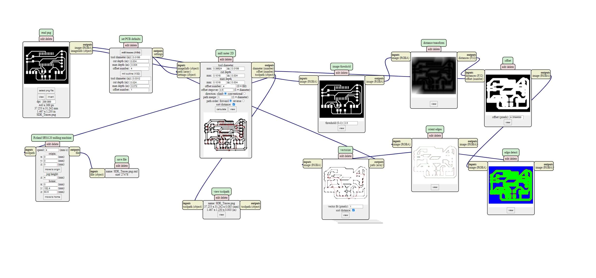
I designed my circuit in a KiCAD schematic and included all necessary components
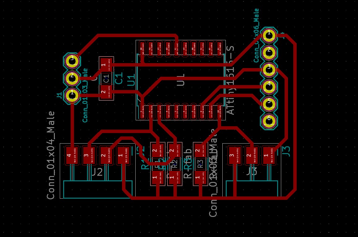
Then, I used KiCAD's built-in tool to create a PCB from my schematic. I then manually routed all of the connections and changed the pin footprints.
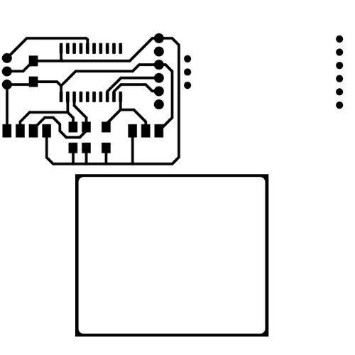
I exported the PCB as an SVG and imported that into Illustrator to design the traces, holes, and outline of my board
I then exported each layer as separate PNGs to import into MODS
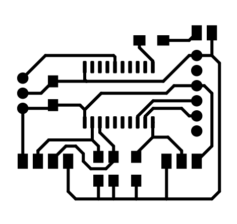
If you look closely at the PCBs above you will notice that I am missing a connection for the piezo buzzer I planned to use for the alarm.
Luckily, I noticed this and added one, as well as a resistor before actually cutting the board (top right).
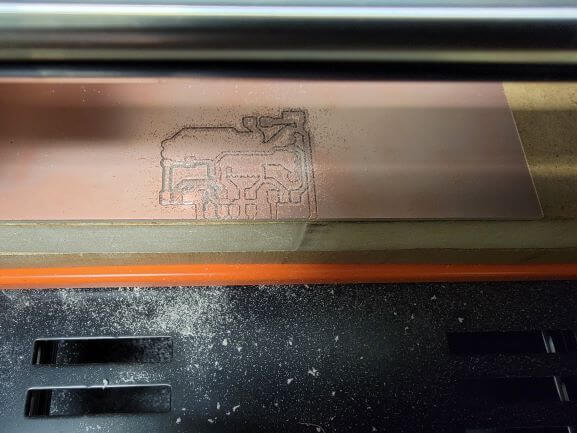
Then I used the RML files genarated by MODS to mill my board!
You'll notice in this photo that I struggled a little bit at first and milled too far down the y-axis. I had the Roland on the setting to accept NC and RML code when it should've just been on RML.
I caught it before things got out of hand and my second board came out great!
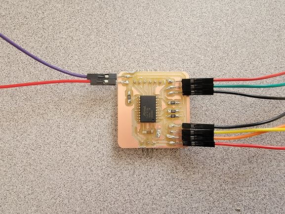
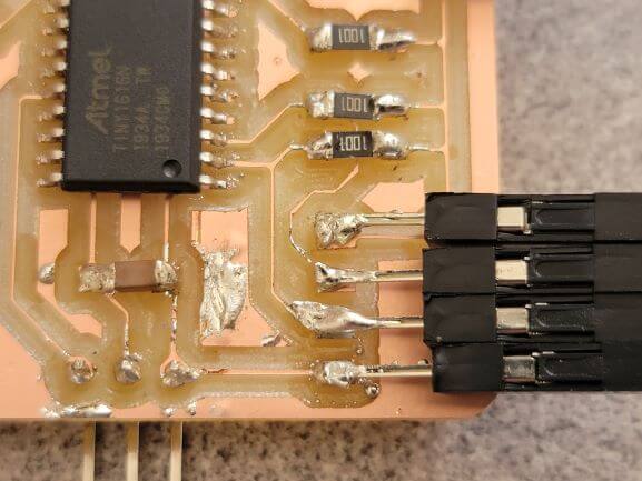
Then I soldered all of the components to my board. I attempted to use the soldering iron instead of hot air this time.
Air soldering is definitely easier, but I prefer the iron! I was pretty messy this time because I was using a chisel-head solder tip that spread the solder too much.
I used jumper wires to connect the input devices so that I could reuse them in the future. In hindsight, I should've changed these footprints to through-hole because soldering these on was a nightmare!
I loaded the Arduino code from TinkerCad into Arduino IDE and uploaded it to my chip using the same process as past weeks.
And the ultrasonic distance sensor in combination with the buzzer worked! Here is is set to sound when something is 10 cm away or less.
Aaaaannnnddd...That's as far as I got.
I struggled for hours trying to troubleshoot the PIR sensor. No matter what I did, every combination of dial turn and jumper position, flipping the wires; nothing seemed to work!
The buzzer sounded when I jumped the pin of the ATtiny that the output of the sensor was connected to. But the sensor's output would never trigger the buzzer.
While attempting to figure this out, I must've shorted something and fried the ATtiny because I could no longer load anything onto it :(
And at this point, it was too late to resolder a new chip.
I'll never forget the first time you said, "BEEP"
At least I got to experiement with the readings of the ultrasonic sensor. I didn't include it in this page because it was not required to use the serial monitor so I did not include a 6-pin programming port on my board. Thus, it is impossible to see that the ultrasonic sensor is constantly giving readings to the board which then converts them to centimeters and activates the buzzer when an object is less than 10 cm away. So, in some aspects, it works like an on-off switch, but it is still constantly processing numbers sent by the ultrasonic sensor.
At the top of this page is the link to all my files this week. The commented Arduino code is there to download and get a better understanding of how the analog signal from the ultrasonic sensor is being read.