Individual: read a microcontroller data sheet and program your board to do something, with as many different programming languages and programming environments as possible
Group: compare the performance and development workflow for other architectures
For the group assignment this week, we split the class in half and each half met separately. While one half programmed as many different boards as possible, the other half observed the behavior of different types of microprocessors and then we switched.
I started in the programming group. Since we had a few different boards on-hand, we split up into smaller groups and each had a chance to program at least 2 boards.
We were able to successfully program a Teensy 4.0 and a generic Arduino Uno.
We also attempted to program a LOLIN32 Pro, but were unable to get it to do anything. Our lab decided that the board is fried because it also got extremely hot to the touch while doing nothing.
Everyone decided to load the basic Arduino "Blink Sketch" to test each board. This program continuously blinks the on-board LED until power is removed.
We were able to program the boards using the Arduino IDE. We really only had to install different microcontroller using the exact same process as Electronics Design Week.
Here's the Blink Sketch working on a Teensy 4.0 (ARM)
And here's it working on the Arduino Uno (AVR)
Everyone also contrinbuted to this spreadsheet that contains the specs of the boards we were working with.
It also includes the links to the documentation for each board that we used to find all of the info.
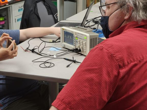
We then swapped groups and began to observe the behavior of different boards. Our lab instructor compared the Teensy to another board (I cannot remember which but it may have been an Arduino Uno).
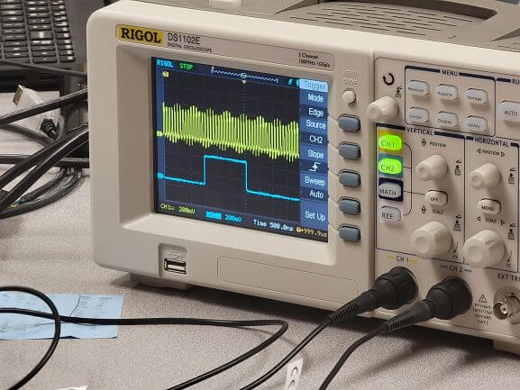
We knew that a multimeter could not handle the rapidly changing currents of the processors' clock cycles. So, we hooked them both up to the oscilloscope separately and then together to compare the clock cycles.
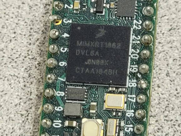
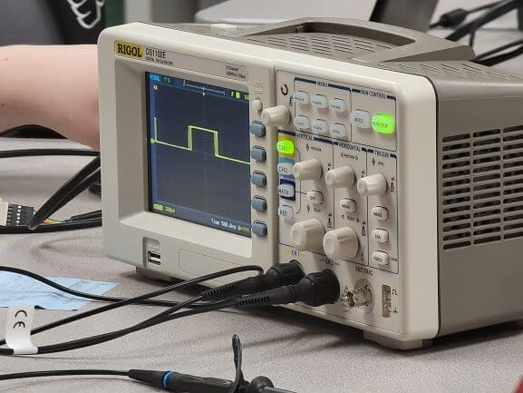
Here's what the Teensy 4.0 looked like
And here's the other board
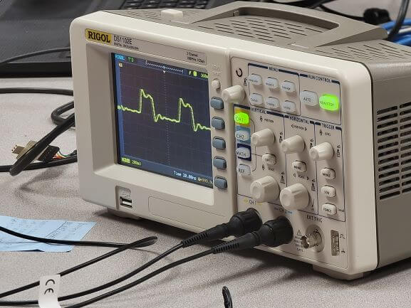
Once we hooked both boards up and dialed in the oscilliscope, you can see the difference in the clock cycle of each.
The top goes through dozens of pulses in the time it takes the bottom to finish one.
Now it was time for the individual assignment, but I had one, small problem. My board from Electronics Design was busted! I got it to run helloEcho that week, but it never worked again after that.
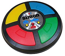
But that's okay because I didn't want to use that boring ol' thing anyways! I wanted to create something more exciting and interactive. So, I decided to make my own version of the Simon!
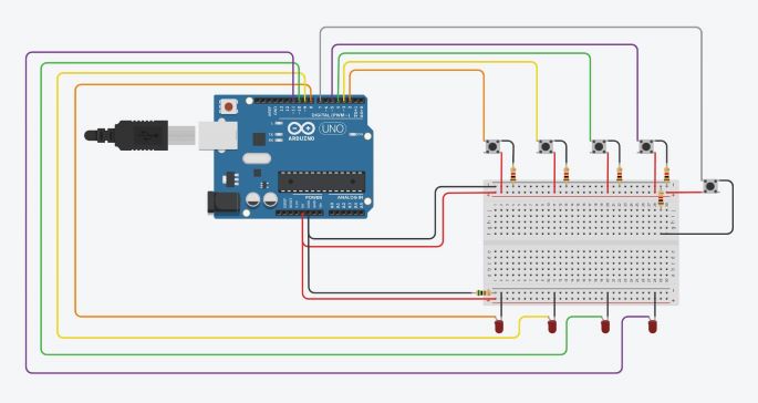
I decided to design the circuit using TinkerCAD's Simulation feature. I knew this idea would work with an Arduino Uno, so that's what I used as my base.
TinkerCAD also make is super easy to code using drag-and-drop puzzle tiles with different functions. Although I didn't use this feature, I did write most of my code in TinkerCAD's built-in IDE.
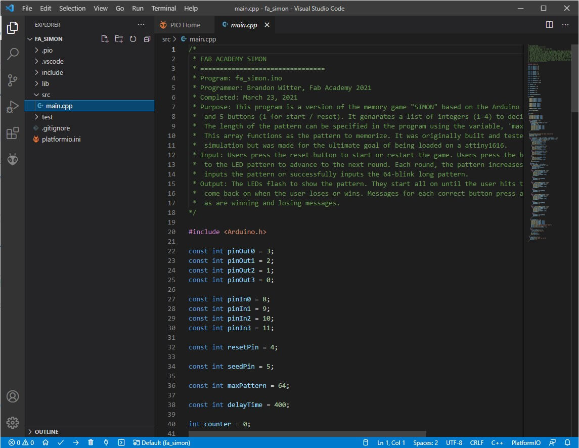
I commented the code the best I could to walk the reader through the process. It's a little confusing since there are so many loops. But, that's how programming a microcontroller goes, I guess!
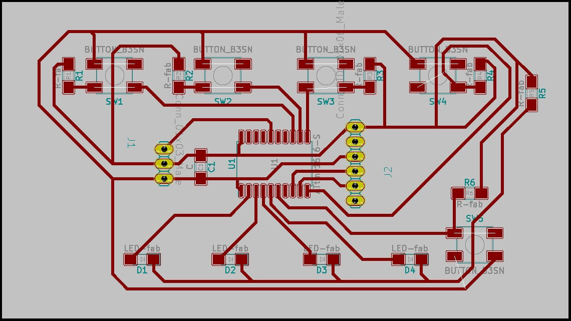
Once I had it working the way I wanted in TinkerCAD, I moved onto KiCAD to design the board.
I based this design around my old board, but added the necessary number of buttons and LEDs. The hardest part was definitely aranging everything in a way that allowed for the connections to work.
Just like my old board, this one also used an ATtiny1616 as the microcontroller.
The process of milling the board was identical to what I outlined in Electronics Design Week.
Genarate PNGs of traces, cuts, and holes and send them to MODs. Use MODs to genarate the RML code for our Roland SRM-20. Mill the traces with a 1/32" ball-nose endmill and cutout the board and holes using a 1/32" fluted endmill.
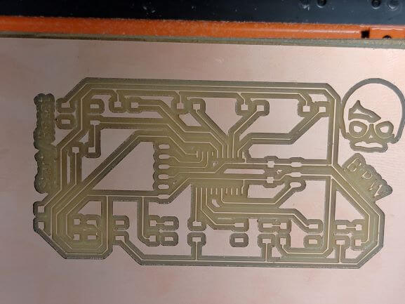
My board cut perfectly first try, but took about 45 minutes to fully finish! I also added some extra flair.
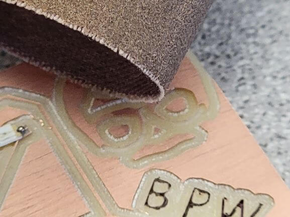
I followed some advice from out Lab's TA to very gently sand the copper face of my board with wet, very fine sandpaper before soldering.
This removes the plastic coating on top of the copper and makes it easier to solder. I definitely noticed a difference, but I was more impressed with the beautiful, brushed finish it gave my board.
I also decided to use a Sharpie to highlight my text because it was too thin to mill properly.
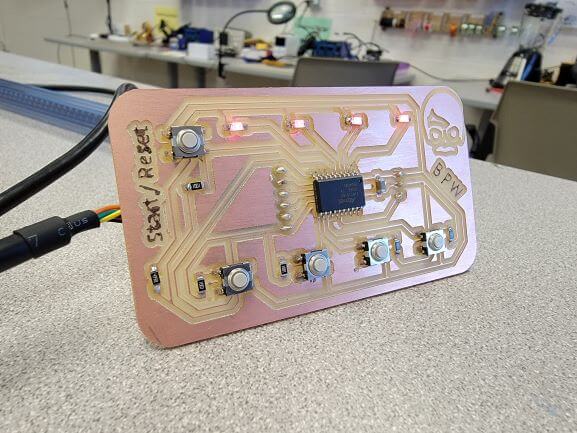
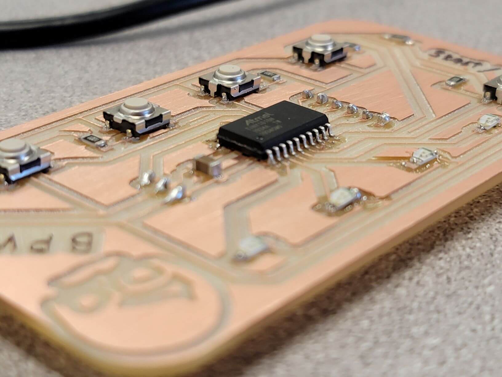
Then I soldered my board and tested each connection. I think this is my best looking board yet! And no, it's not just because my face is on it...
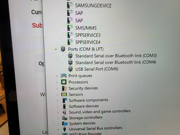
Before I could program my board, I had to fix a problem that was stopping me from going any further. I learned from Electronics Design Week that my laptop doesn't recognize the ATtiny1616 when it is plugged in via USB. I couldn't even selct the COM port in the Arduino IDE.
Luckly, a few other students had ran into this issue with their Windows laptops and new the fix. It involved installing the correct VCP drivers from FTDI Chip's Website.
Once I installed the drivers, COM6 showed up in my device manager whenever my board was plugged in. Amazing!
Now I was ready to program my board using the Arduino IDE. It is also required to install megaTinyCore via the Board Manager in Arduino if you haven't already (I had).
This allows for Arduino to recognize and program ATtiny Chips. Sure enough, my ATtiny1616 was on the list!
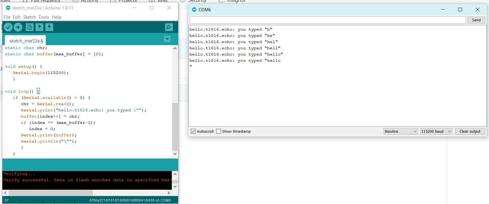
I was then able to install and run helloEcho on my board! Note that the 3-pin header is for programming and you must use the 6-pin header if you wish to see output on the Serial Monitor.
Uploading via the Arduino IDE is as easy as hitting the top left arrow next to the check mark after selecting the correct COM port and board from the Board Manager.
Now it was time to try my code! I loaded it, and...the lights were randomly flashing.
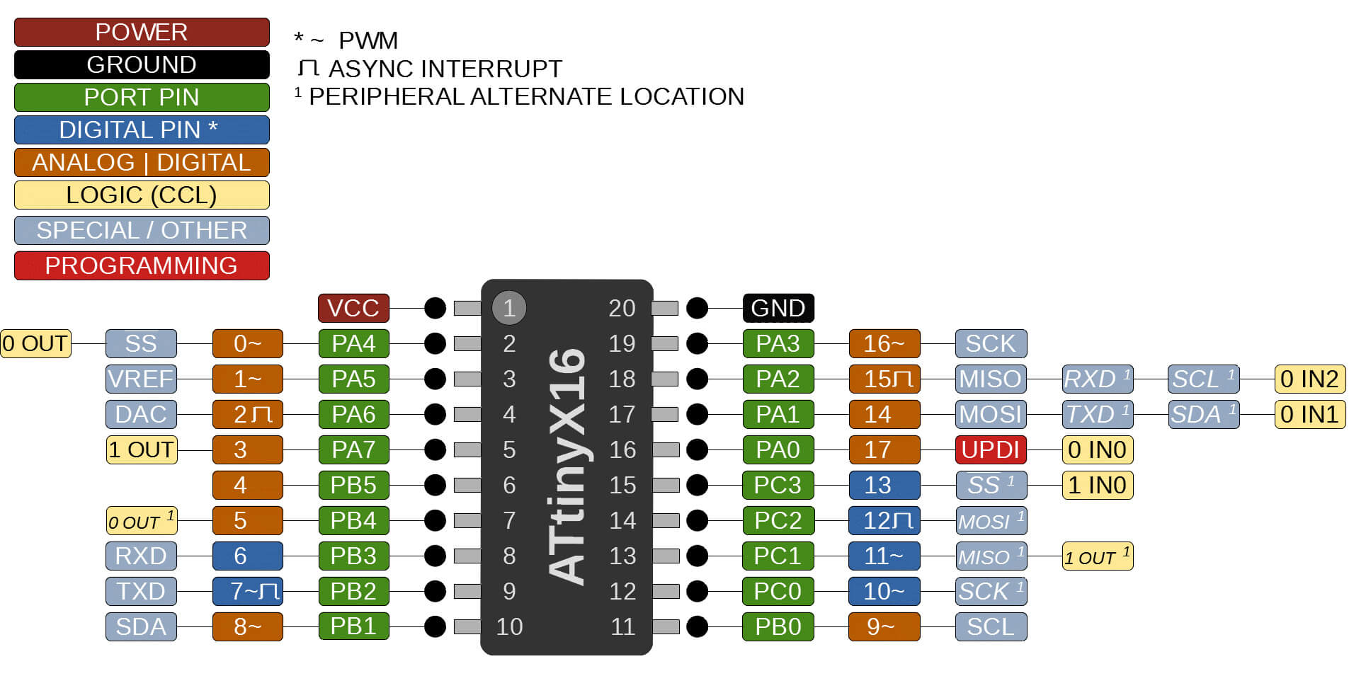
After a little torubleshooting and brainstorming in the lab, it turned out my pin numbers were wrong. I had changed them to reflect the ATtiny, but I was actually reading the wrong number on the pin diagram below.
This could have been disasterous. But luckily, the worst that happened was that I had to use a few more analog pins for digital functions than I expected.
Here's the pin diagram I was referencing. I was looking at the labels on the silver pins rather than the labels on the orange and blue pin labels!
So, from left to right on my board, the LEDs use pins [3, 2, 1, 0], my buttons use pins [8, 9, 10, 11], and my reset button uses pin 4.
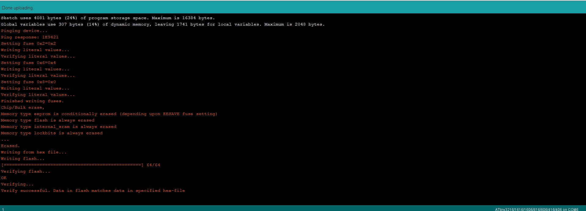
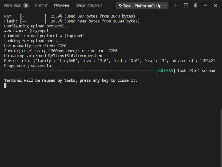
Here's what a successful upload using the Arduino IDE looks like.
Here's a video of the board in action!
And here's what happens when you get one wrong or hit the reset button on your turn. The LEDs all turn on and you must hit the restart button again to start a new game.
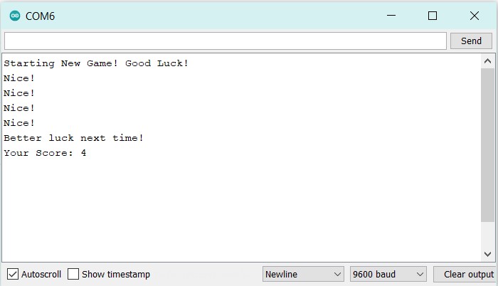
And here's an image of the serial monitor after losing on a pattern of 5 lights.
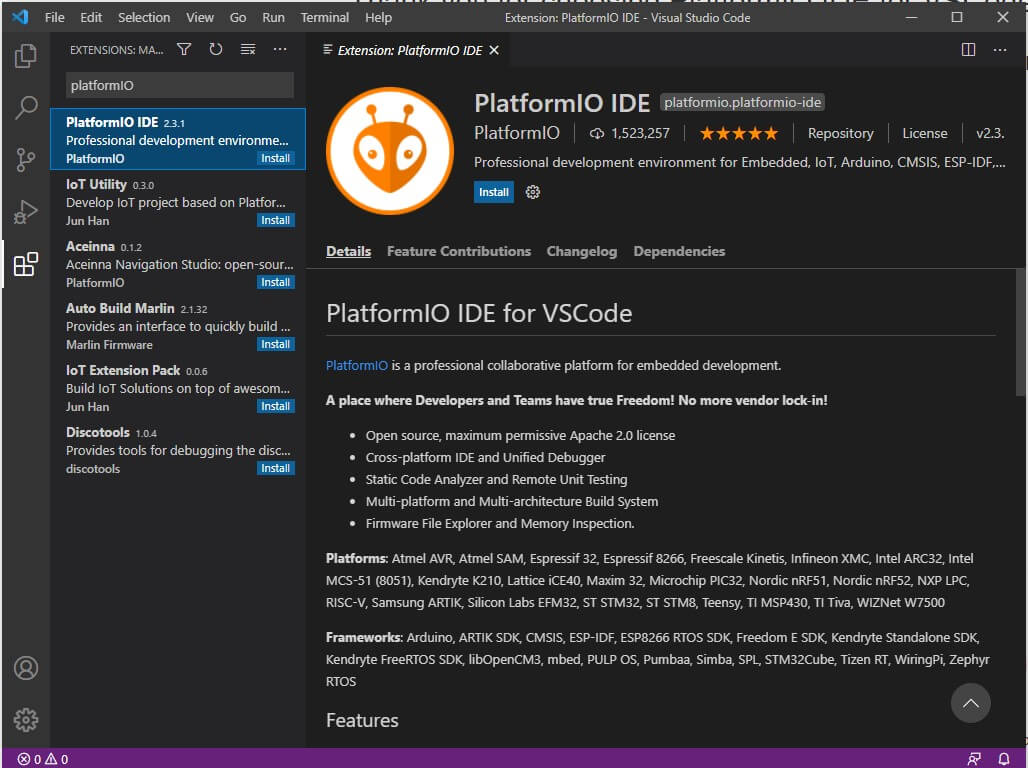
Next, I wanted to use Visual Studio and PlatformIO to program my board using the same Arduino code as before.
Using the Extension Manager in Visual Studio, search for "PlatformIO IDE" and install that
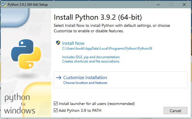
While it is installing, we need to set up Python. Grab the installer and select "Customize Installation"
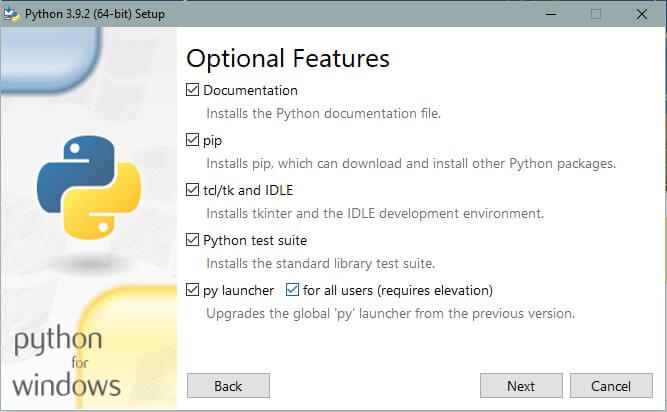
You can leave everything checked on the Optional Features screen
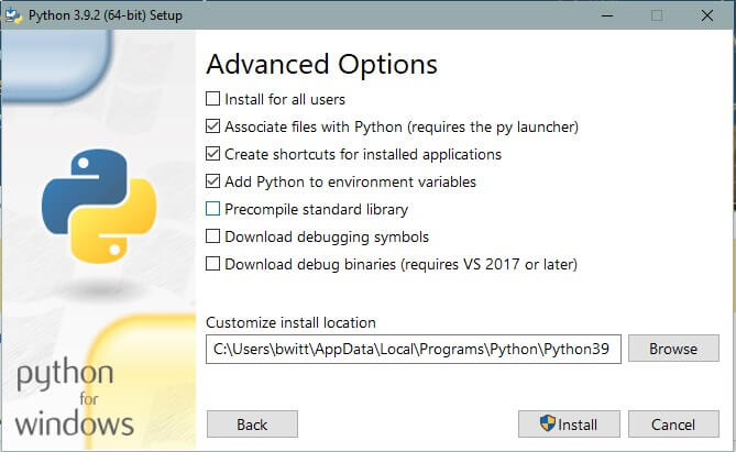
IMPORTANT: Make sure "Add Python to environment variables" is checked!
Now, open up the command prompt and run the command 'pip install git+https://github.com/mraardvark/pyupdi.git' to install pyupdi which is needed for PlatformIO.
The command 'pip' is why we needed to add Python to environment variables.
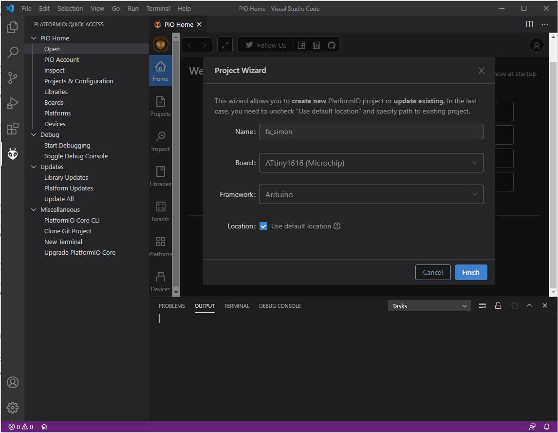
Now, PlatformIO was installed so I made a new project using the ATtiny1616 as my board and Arduino as my framework
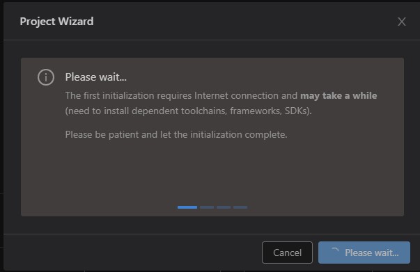
Then wait for PlatformIO to install what it needs to
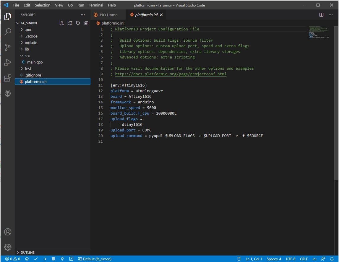
Once the project is created, you will see a bunch of tabs to the right.
First, I replaced the contents of 'platformio.ini' to match my .ini file. This allows pyupdi to upload to my specified COM port (COM6)