Group: use the test equipment in your lab to observe the operation of a microcontroller circuit board
Individual: redraw an echo hello-world board, add (at least) a button and LED (with current-limiting resistor), check the design rules, make it, and test it
This week, I was able to make an (almost) working board. By that, I mean that it worked once and then never worked again.
I'll try to go through what went well, what went wrong, and what frustrated me beyond belief this week.
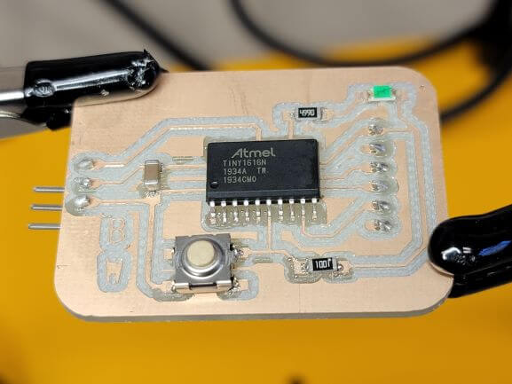
We first had to complete the group assignment using boards made by our instructors. These boards used an ATTINY-1616 chip to start a count down from 10 after a the button is hit and flash a red LED every second until the countdown is complete.
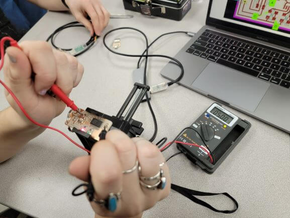
We started by using multimeters to observe the voltage as the board was in use. The image to the left shows us measuring the input voltage of 5V.
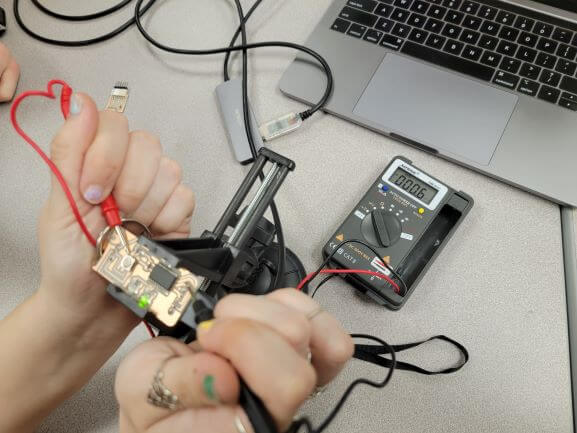
This next image shows the voltage when the LED is flashing. We measured the voltage going through the LED and noticed that when the LED is on, we get 5V. When it is off, it is closer to 0.
The image to the right shows the lower voltage when the LED is off. Notice how it still reads 0.6V. This could be because the multimeter cannot keep up with the rapidly fluctuating voltage of the light flashing on and off.
Here is a video that better shows the fluctuating voltage as the LED flashes. The red LED flashes very quickly so I think it got cut when I lowered the frame rate of this footage.
We also used an oscilloscope to observe the voltage through the LED as it flashes. Notice how the graph spikes when the LED flashes on.
Now that we had observed the behavior of a milled circuit board, it was time to design one of our own!
I chose to use KiCad because it seemed like most others prefered it over Eagle. I installed KiCad
here
and downloaded using the OSDN link for Asia and North America.
Then the KiCad installer guided me through installation and I kept everything at their recommended settings.
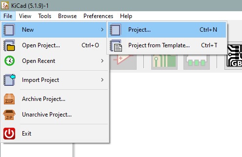
With KiCad open, the next step is to create a new project.
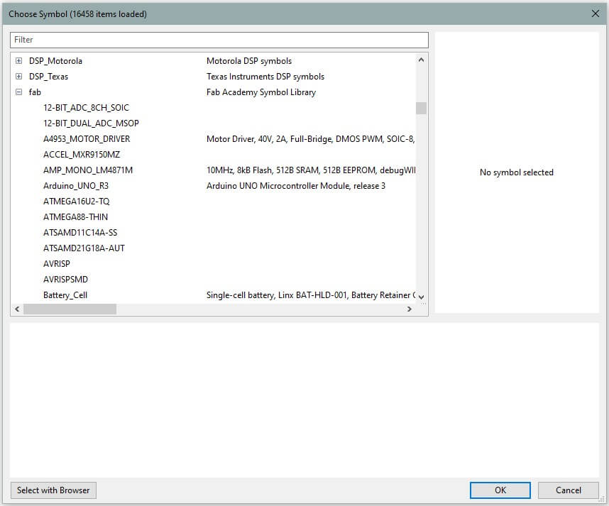
Once you have a new project, you can import the library for fab components. The link below is where you can download this library as well as view detailed instructions on how to import them into KiCad.
One of our lab instructors also started to create a library for the components that Wheaton has on hand. The instructions to download are identical to the ones above except for the variable names. Use "wheaton" instead of "fab".
Once the libraries are installed, they should appear as libraries when you are searching for components.
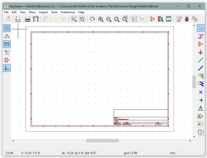
To build the circuit in KiCad, you must use the Schematic Layout Editor. Here you can search for components, place them, and wire them together to create a ciruit.
The schematic simply tells KiCad what should be connected to what and does not reflect the final shape of the circuit.
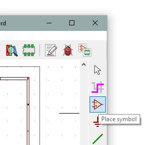
To search for and place components in KiCad, you use the 'place symbol' button.
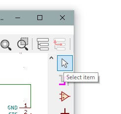
You can use the 'select item' button to hover over a component and hit the 'm' key to move it or the 'r' key to rotate it.
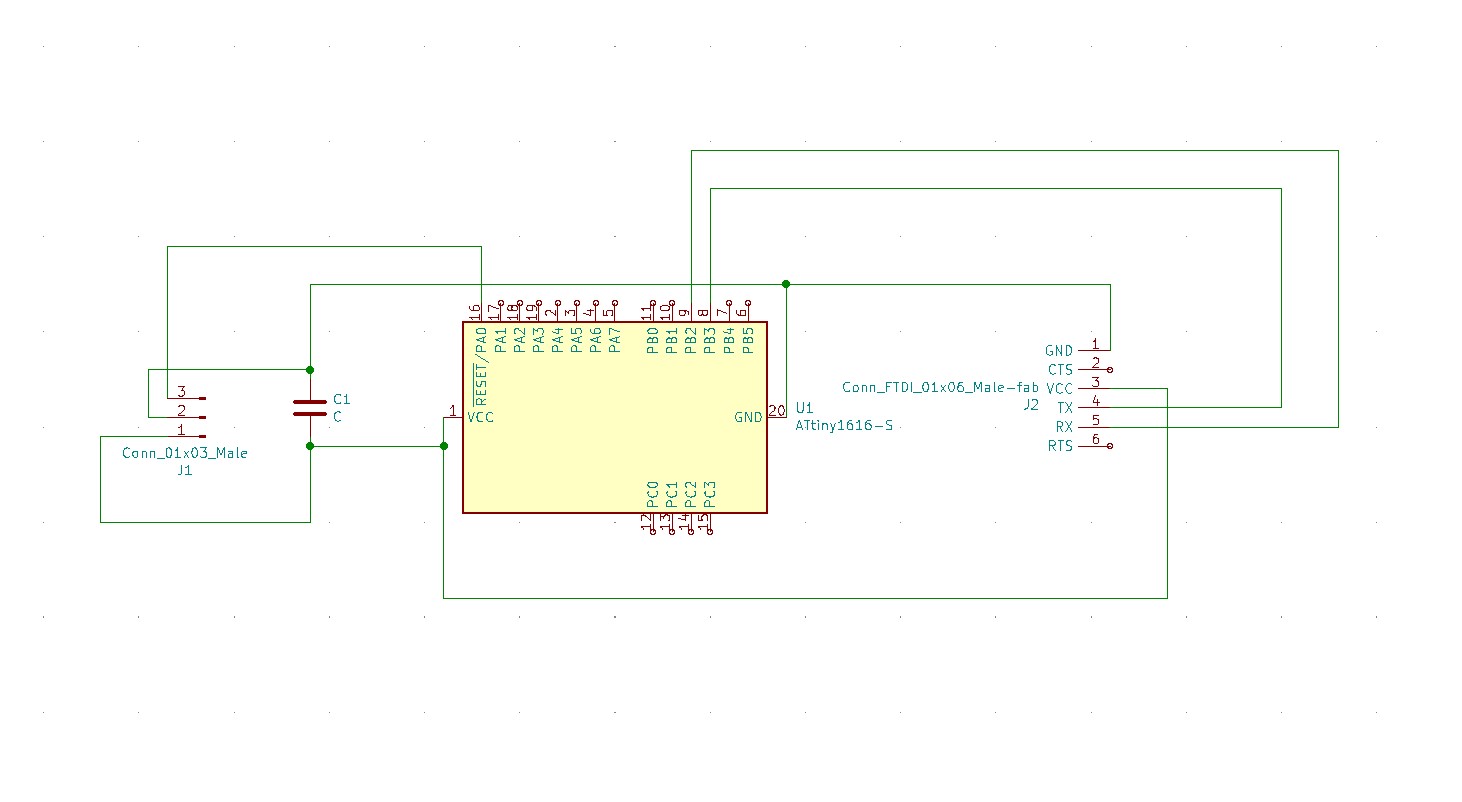
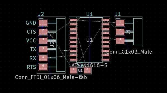
Following the tutorials of our lab instructor, I connected a circuit to control our ATTINY-1616 chip. Here's what the circuit looks like.
It is important to note that the assignment calls for a 1614 chip, but our lab had none and they are totally backordered. Instead, we substituted for the 1616.
I then added a button and LED to this circuit. The idea was that the button connects the 5V power source to pin 6 of the 1616. And the LED and resistor are connected to pin 13. Both these pins are digital meaning that they are either HIGH or LOW.
So, when the button is pressed, pin 6 would recieve a HIGH signal which could trigger pin 13 to output a HIGH signal. that way, the LED could react to a button press.
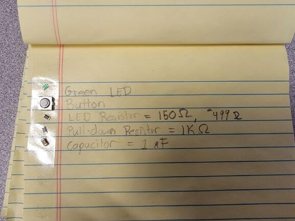
There are a few things I would like to explain about my circuit design. Firstly, there is a pull-down resistor between pin 6 and ground. This ensures that pin 6 remains LOW and isn't a 'floating' when there is no voltage going to it.
Secondly, I didn't need to know the values for the resistors or the capacitor while laying out the component connections. This is only important once it comes to soldering. But, I knew that the pull-down resistor just had to be an arbitrary, high value. I chose a 1kOhm resistor for this. And for the capacitor, I chose a 1μF that supported up to 30V.
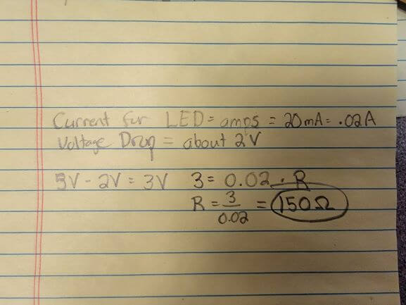
The math for the resistor that connects the LED is below.
I wanted to use a Green LED and so I looked up the specs for some similar to the ones we have at Wheaton.
I found that they have a voltage drop of about 2V and a maximum current of about 2 milliamps, or 0.02A.
Using Ohm's Law (V=IR), our neccessary resistance comes out to 150 Ohms.
Buuuuuuut, the closest value we had in our lab was 499 Ohms and that's what I used.
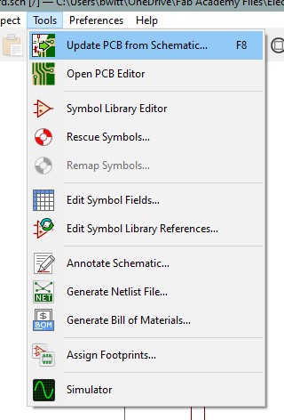
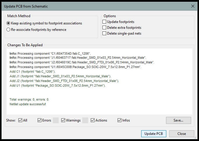
Then we can hit 'Update PCB from Schematic' and let KiCad do its thing.
And hopefully, you end up with a window like this with no errors! Hit 'Update PCB'.
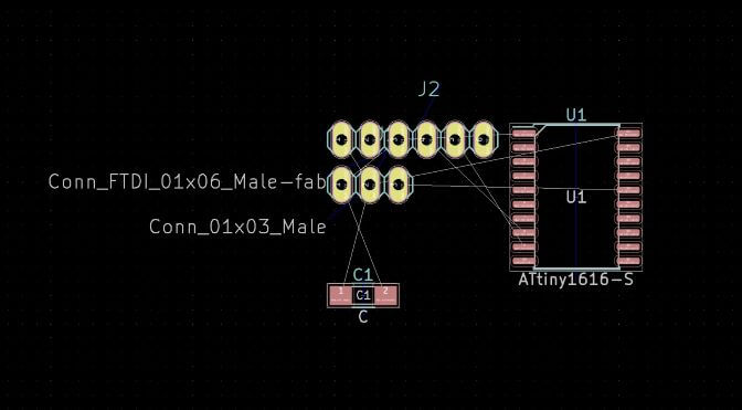
That should result in a layout of your components and faint lines to represent components that should be connected.
Please note that the above image is from before I added an LED or button.
Also, we are using through-hole pin headers, and the symbol above is for surface mounted.
To change that, select 'Assign PCB footprints to schematic symbols' and then select the component you want to modify from the list.
The through-hole footprints look like this (yellow).
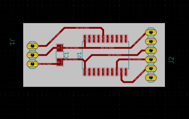
Then layout your components in a way that makes sense and connect them using the 'Route tracks' tool. I set track width to 0.5mm to be safe.
You'll know when all tracks are traced because you will no longer see the faint white lines connecting the components that still have to be connected by tracks.
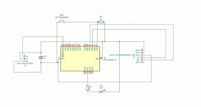
Above is my design with no button or LED.
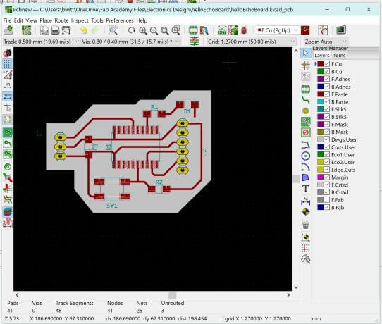
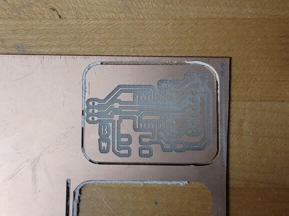
Here is my final design with the button and LED added. Note that the gray background is drawn on the User Drawings (Dwgs.User) layer.
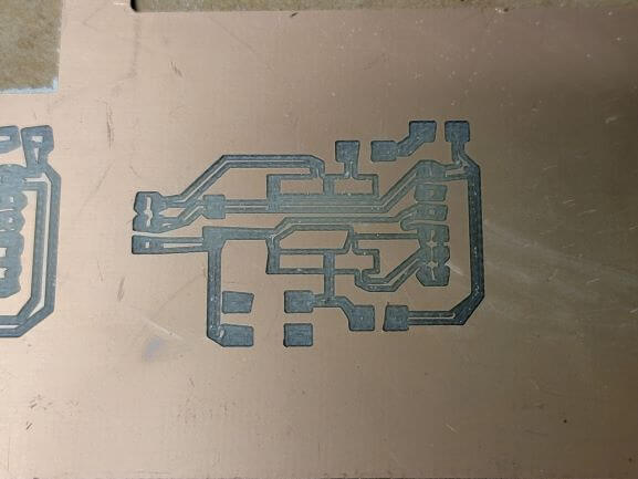
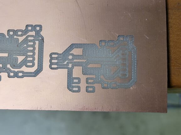
Now to export and mill my design, I tried a bunch of different methods, but I'm only going to cover the one that worked.
But first, let's briefly cover each of my failures. All of these started by exporting the SVG of my circuit from KiCad.
Failure 1: Used MODS but forgot to invert image
Failure 2: Used MODS but PNG was exported at 72 ppi, much too low
Failure 3: Attempted to use FlatCAM with tool diameter of .4mm and cut depth of .1mm
Failure 4: Attempted to use FlatCAM with tool diameter of .4mm and cut depth of 0.05mm
Failure 5: Used MODS with PNG exported at 300 ppi (also added ititials). Looks great but wasn't taped properly so didn't cut through.
Attempt 6: Success! Used same settings as Failure 5, but taped down better. Also forgot to take a picture here...
I wrote down all of the components that I needed and stuck them on double-sided tape to bring tho the soldering station.
Then I soldered them all on where they belonged. Nothing super interesting happend while soldering, but it took roughly 45 minutes to finish.
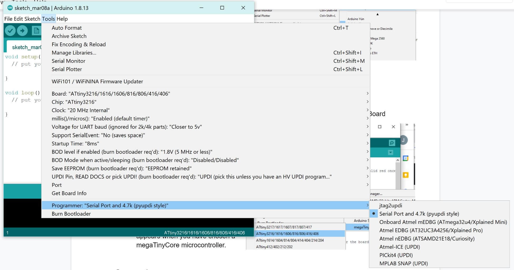
The first step to program the board is to download the latest release of Arduino.
Download Here
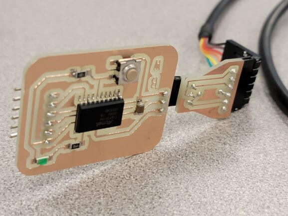
Then I selected ATTINY-1616 as my board in the settings, copied Neil's code into the Arduino IDE, plugged my board into my USB port using the adapter cable, hit upload, and...
NOTHING!
The code stayed on 'upload' infinitely and I realized its because of an issue with my COMS ports. The only ones to show up in my arduino menu (and device manager) are COM2 and COM3, both of which are bluetooth channels only. When I disable bluetooth, I couldn't even select the port option.
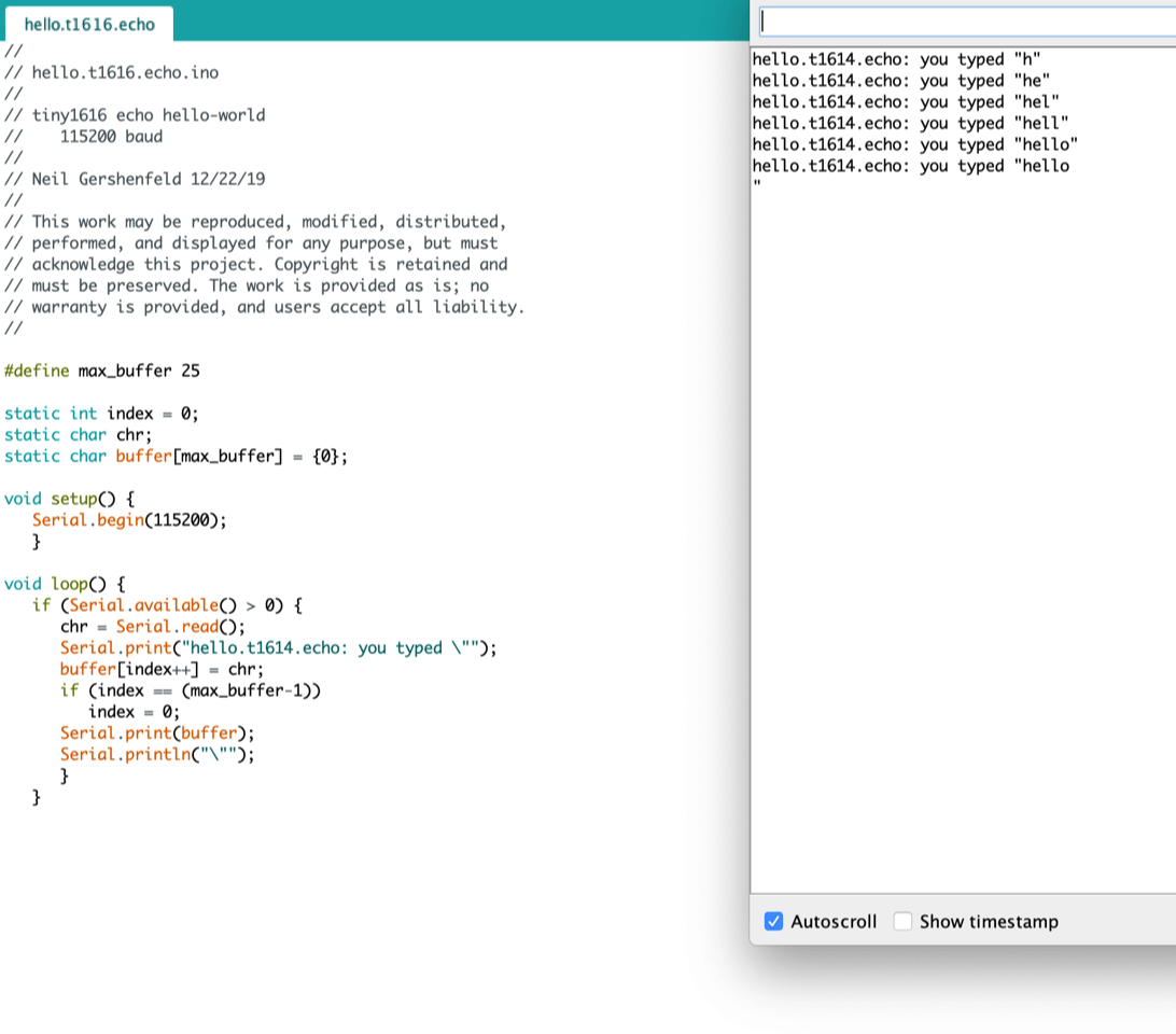
So, I decided to borrow someone's computer that had it working and I was able to get the hello echo code to work!
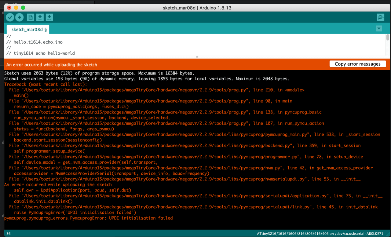
And that's all my board ever did. From this point on, the LED lit up when plugged in but the board is no longer recognized by Arduino. I can't load or run any other scripts on it. All I get is this error.
Maybe my board got fried. Who knows?
I'll never forget the first time you said, "hello." <3