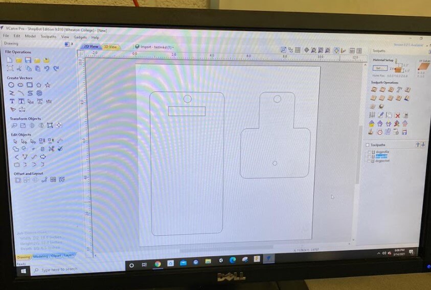
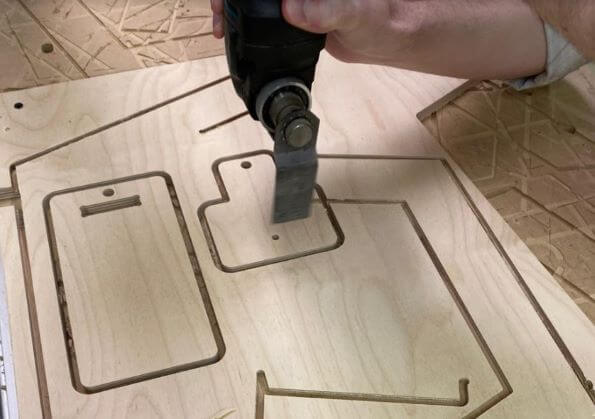
For the group assignment this week, we used VCarve to CNC a wooden phone stand that our lab instructor designed.
You can see that the design includes both cuts and a drill hole.
However, this design would not work because the top peg of the righ shape has to fit in the rectangular slot of the left shape. The CNC can not cut inner, right angles!
I'm not going to go in-depth on the steps of cutting using VCarve because I found Fusion to be a much more powerful tool for this. I will go into a lot of detail about CNC milling with Fusion 360 a little later.
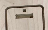
To allow the peg to fit, we had to do something called 'dogboning' where the corners are cut out as a circle.
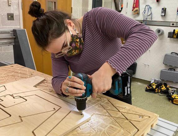
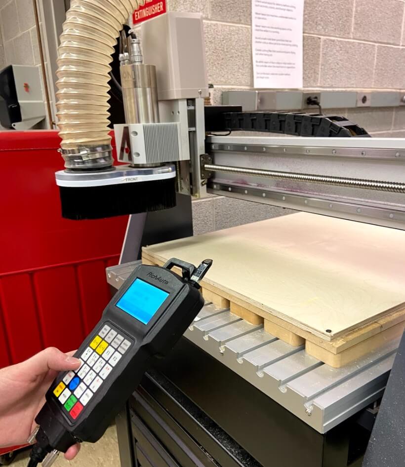
Before we could cut, we had to anchor the material with double-sided tape and screws.
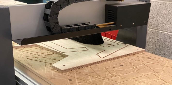
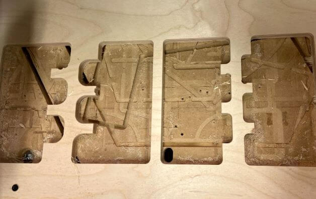
We then cut the file using the CNC machine.
And we cut the tabs to remove the 2 pieces.
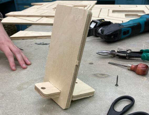
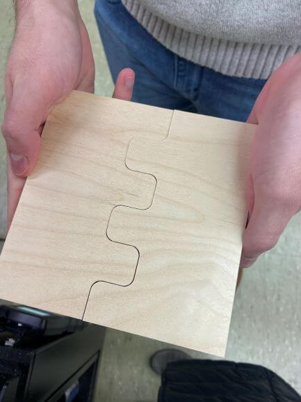
As you can see, the pieces fit together since we were able to dogbone the corners.
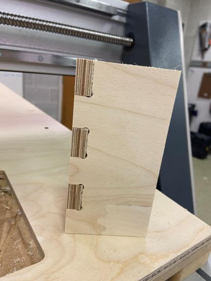
This was designed such that there was no clearance between the hole and the peg, so we did have to hammer it in.
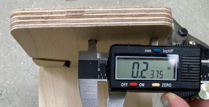
We measured the hole that was drilled assuming it would be exactly 1/4" since that is the diameter of the endmill.
Strangely, it measured 0.2375". This was most likely due to wood shrapnel around the circumference of the hole.
To understand my project this week, you need a little bit of background information.
A group of students at our Fab Lab is teaming up for Machine Design week to create a 'Smart Bar' where you can mix and match chilled drinks. We have already done some research as to what parts are required, so we have a basic understanding of the neccessary dimensions of the actual bar enclosure. So, that is what we are designing and building this week; an empty shell that is big enough to fit a small fridge and all the plumbing for our bar.
Emma Yount and I teamed up this week to pool our materials and design the bar. Check out her website here!
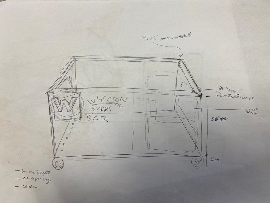
The first step in designing our bar was to create a sketch. Normally, I do this in Illustrator, but pen and paper does the trick, too!
We decided that the height of our counter should be about 36" since that's what seemed comfortable. This also meant that the front of our bar had to be made out of 2 sheets of the 2'x4' plywood. We chose to use our knowledge from the Computer-Controlled Cutting week to fit everything together using box joints.
That meant that the dimentions of our bar would be roughly 48" long x 24" deep x 36" high. Of course, these dimentions changed a little bit while actualy modeling our design.
To model the front, we made a rectangle that was the width of 2 pieces of plywood put next to each other. We accounted for a 1/2" cut margin around the entire board meaning that the boards could be up to 23" wide when fully cut.
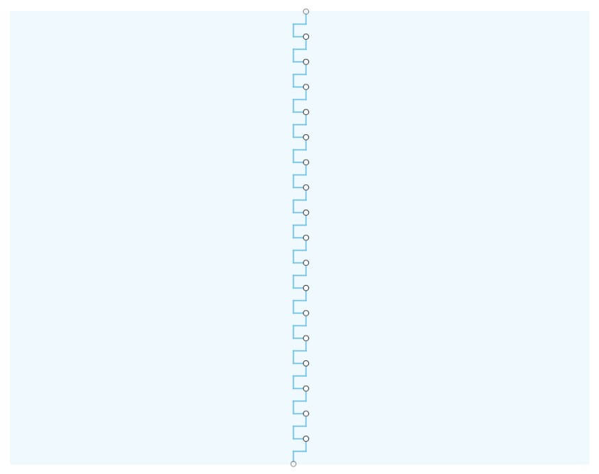
Then, we made made a sketch on the surface of this body of a rectangular pattern down the center to simulate the fingers and grooves that make up a box joint.
We used the technique in the following video to make finger joints that account for the clearance needed between fingers. We decided to use a clearance of 0.01" (1/64"), but the design is parametric, so this can easily be changed!
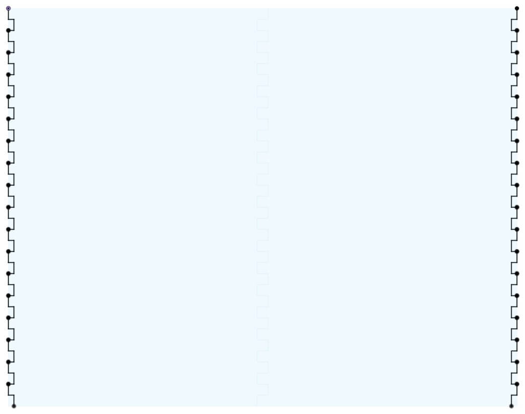
Then we did the same on the sides, except with more shallow grooves and fingers to make the side panels flush with the front.
Once we cut out this pattern, our design looked like this. This is the front of our bar.
Here is a closeup of our 0.01" clearance gap between the grooves and fingers.
This clearance can easily be changed by changing the variable assigned to it. In fact, this whole design was built parametrically!
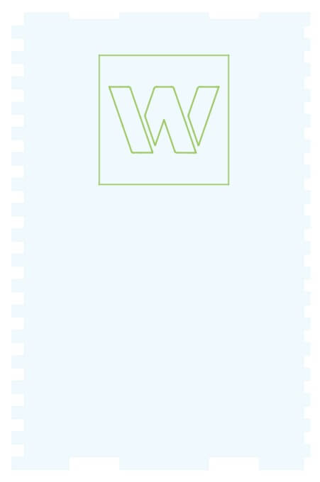
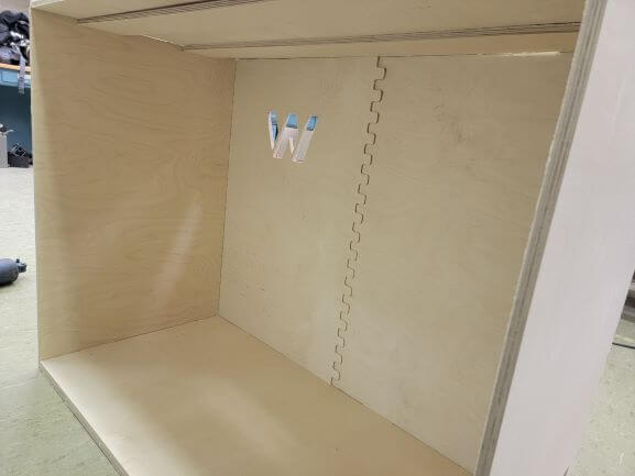
We wanted a Wheaton Logo on the front panel that we could put colored acrylic and an LED behind. This was created by importing an SVG of our logo.
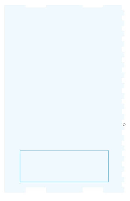
We new that the fridge we are going to use vents on it's right side, so we incorporated this in the corresponding side panel.
The side panels were designed by following the same rectangular pattern technique, except only on one side.
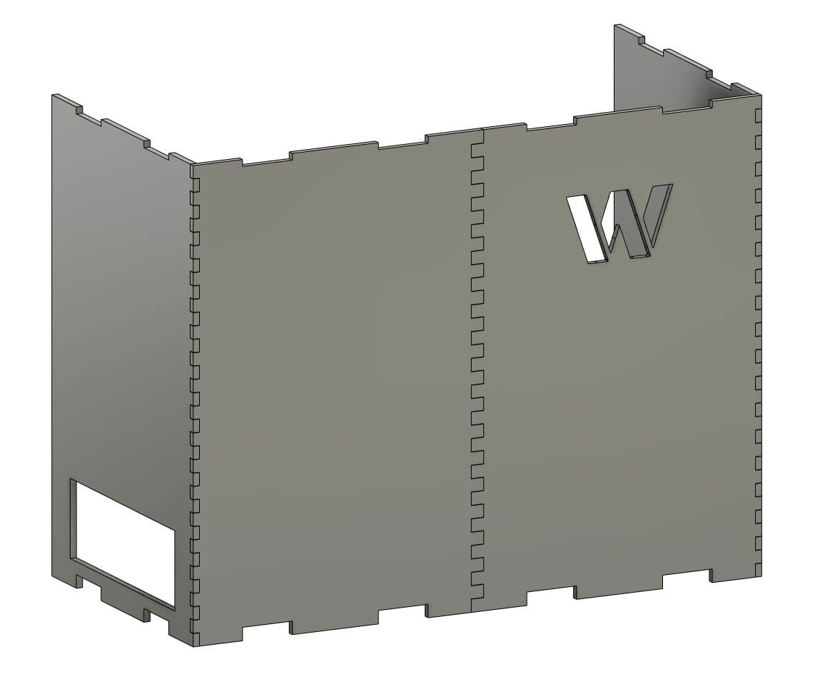
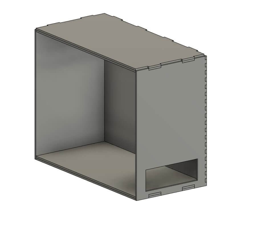
We put everything together and this was the result.
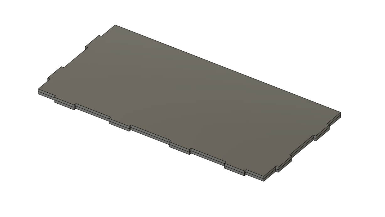
The grooves along the top and bottom were created using this design as the base and countertop. We wanted them to be 2 boards thick for strength.
Now, we were almost done!
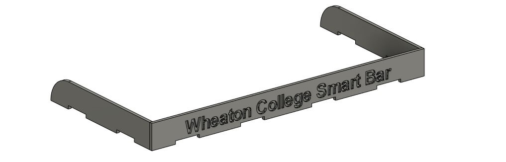
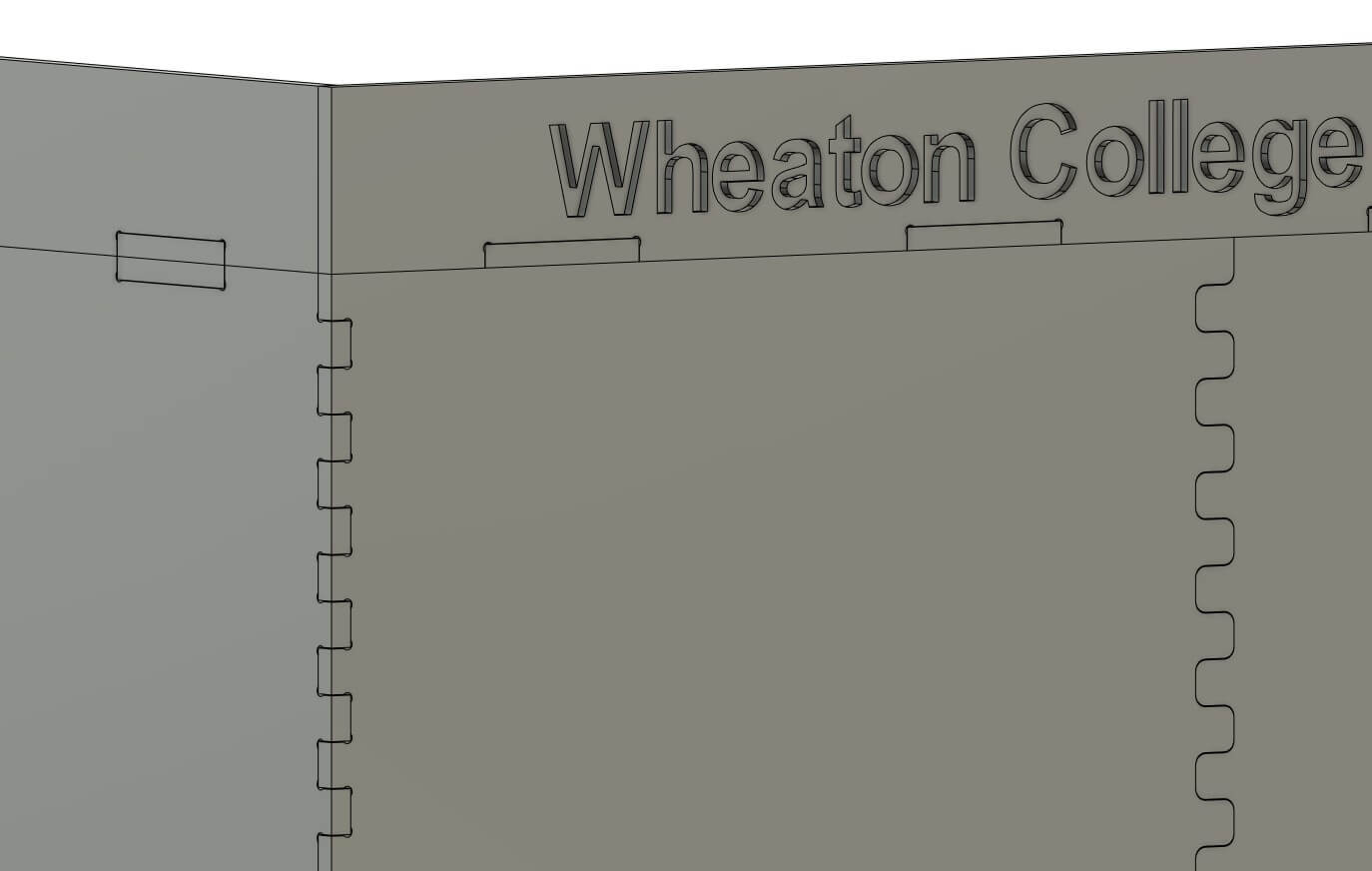
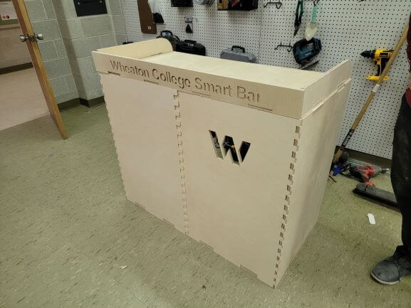
The design felt too empty at this point. We decided to model a sign to wrap around the top.
This sign also functions as a barrier from any liquids or cups from falling off the top. Plus, it looks really nice!
The text was created using the text and push/pull tools in Fusion 360. The text is 0.25" deep: half of our material thickness.
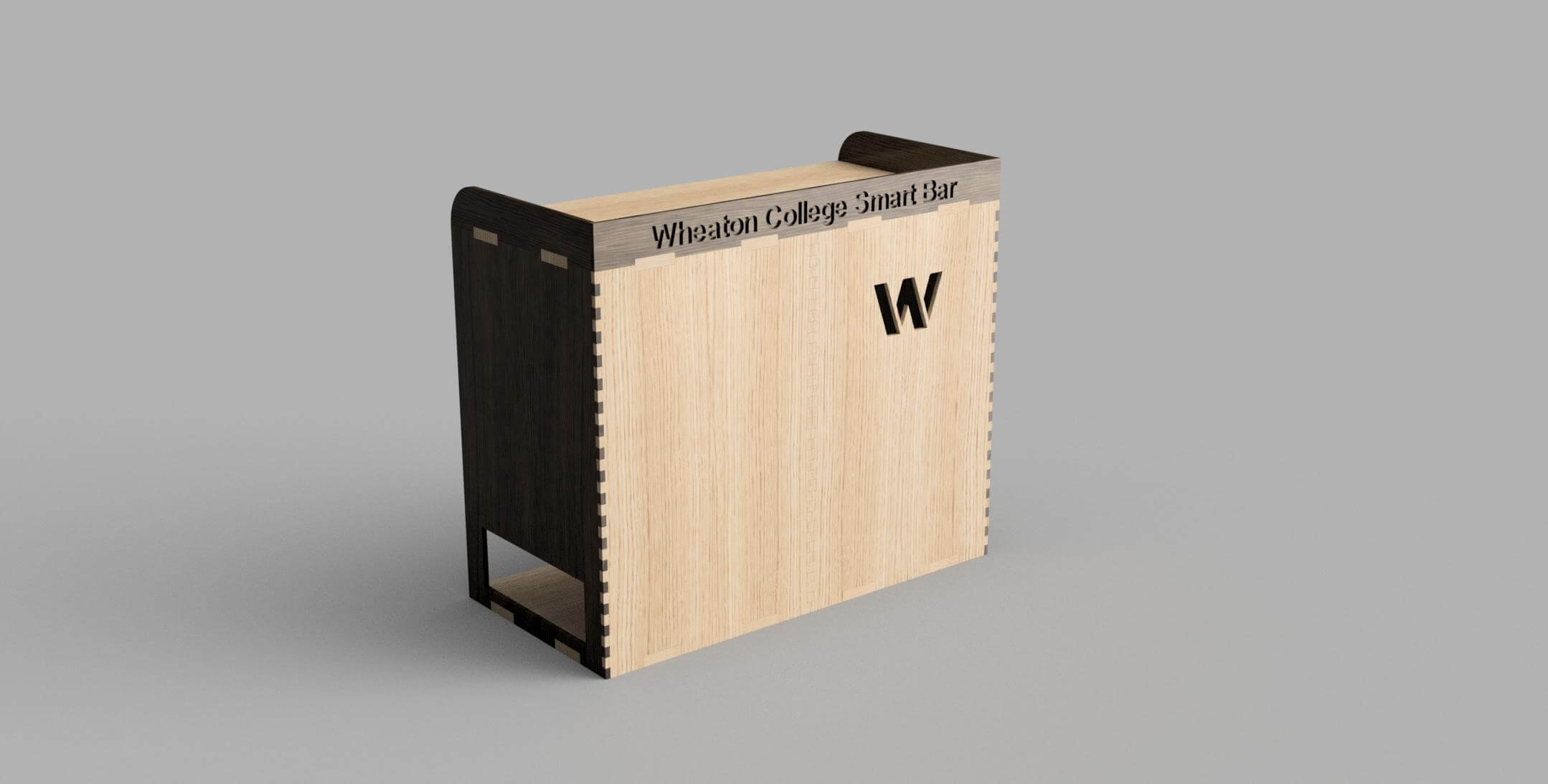
Then, we applied materials to simualte the wood stain we want to apply to our bar. We used Fusion's built-in redering to genarate these images.
This is the front-view.
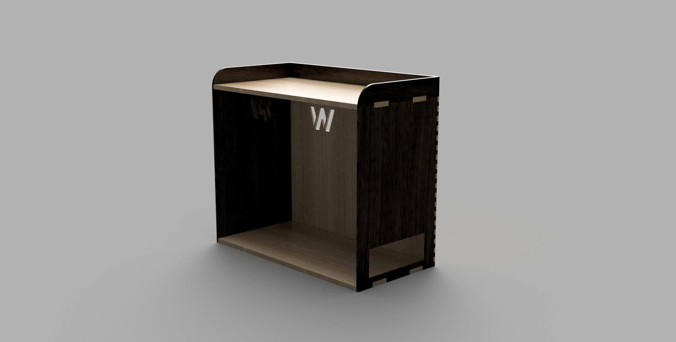
And the back-view.
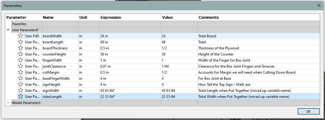
And finally, here are the parameters that we used to design the bar.
After we had gotten to this point, we had the lab with our instructors that clarified how a CNC works and what it is actually capable of. I sumarized that lab at the top of the page.
But it was after this lab that we decided to modify the design a bit to ensure that it could successfully be cut in our CNC.
The reason we had to modify our previous Fusion design was because it relied on perfect, inner right angles in order for the joints to stay together.
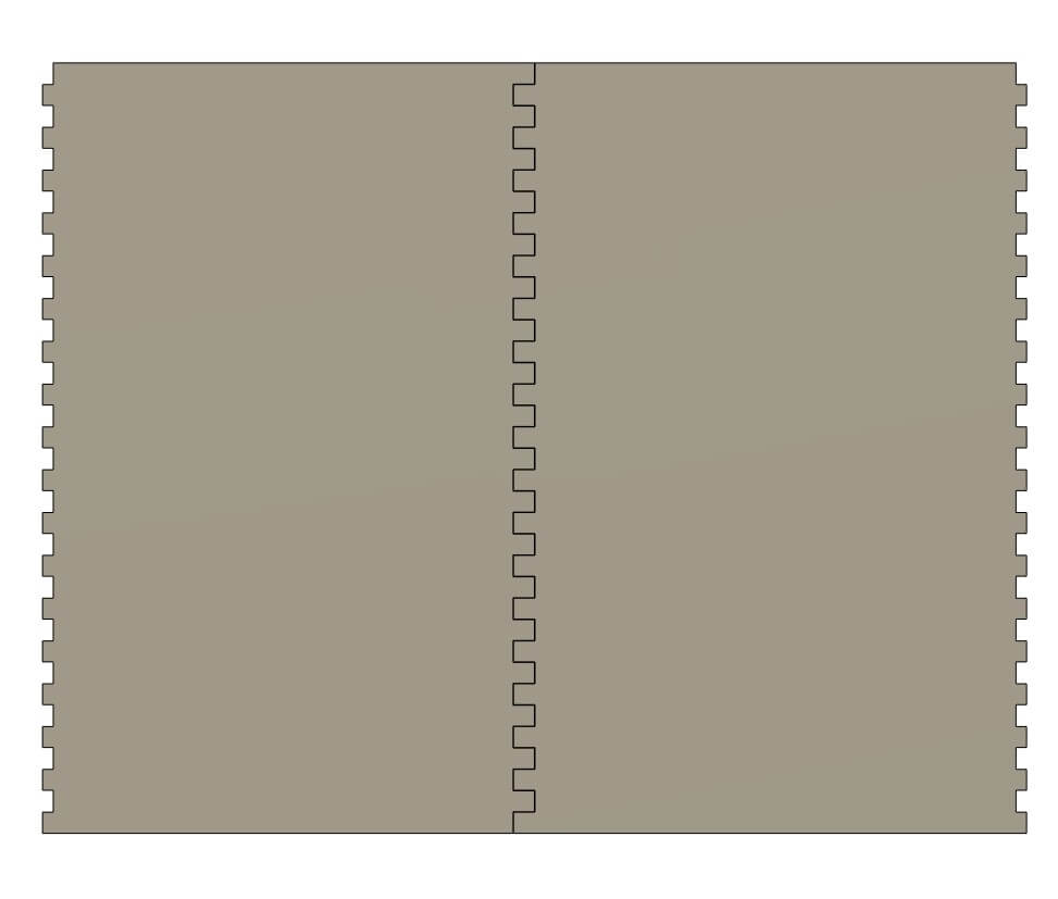
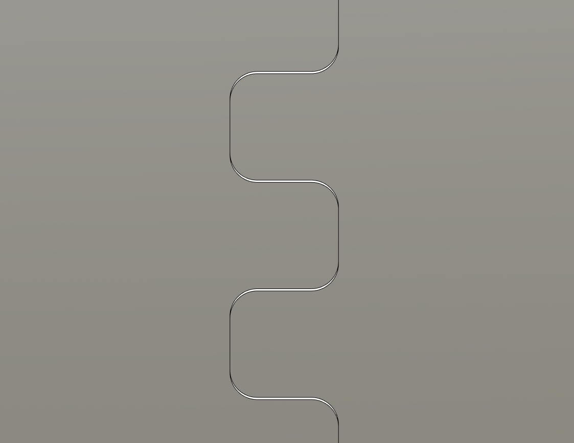
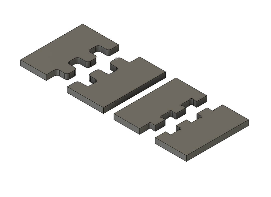
The first change we made was to round all the corners of the middle front joint.
Now, instead of sharp, right angles, the middle joint relies on curved corners.
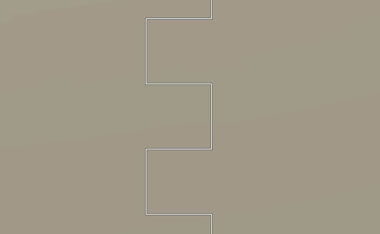
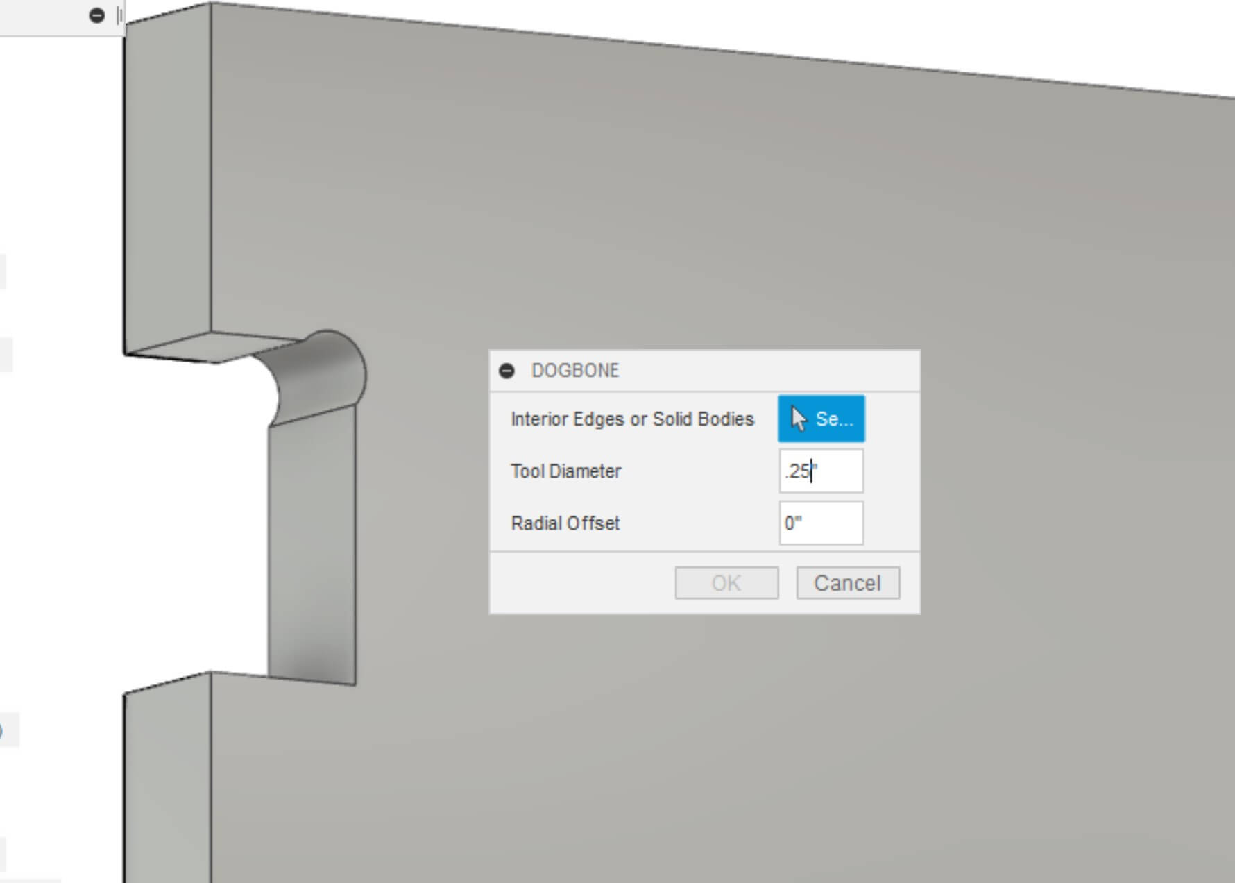
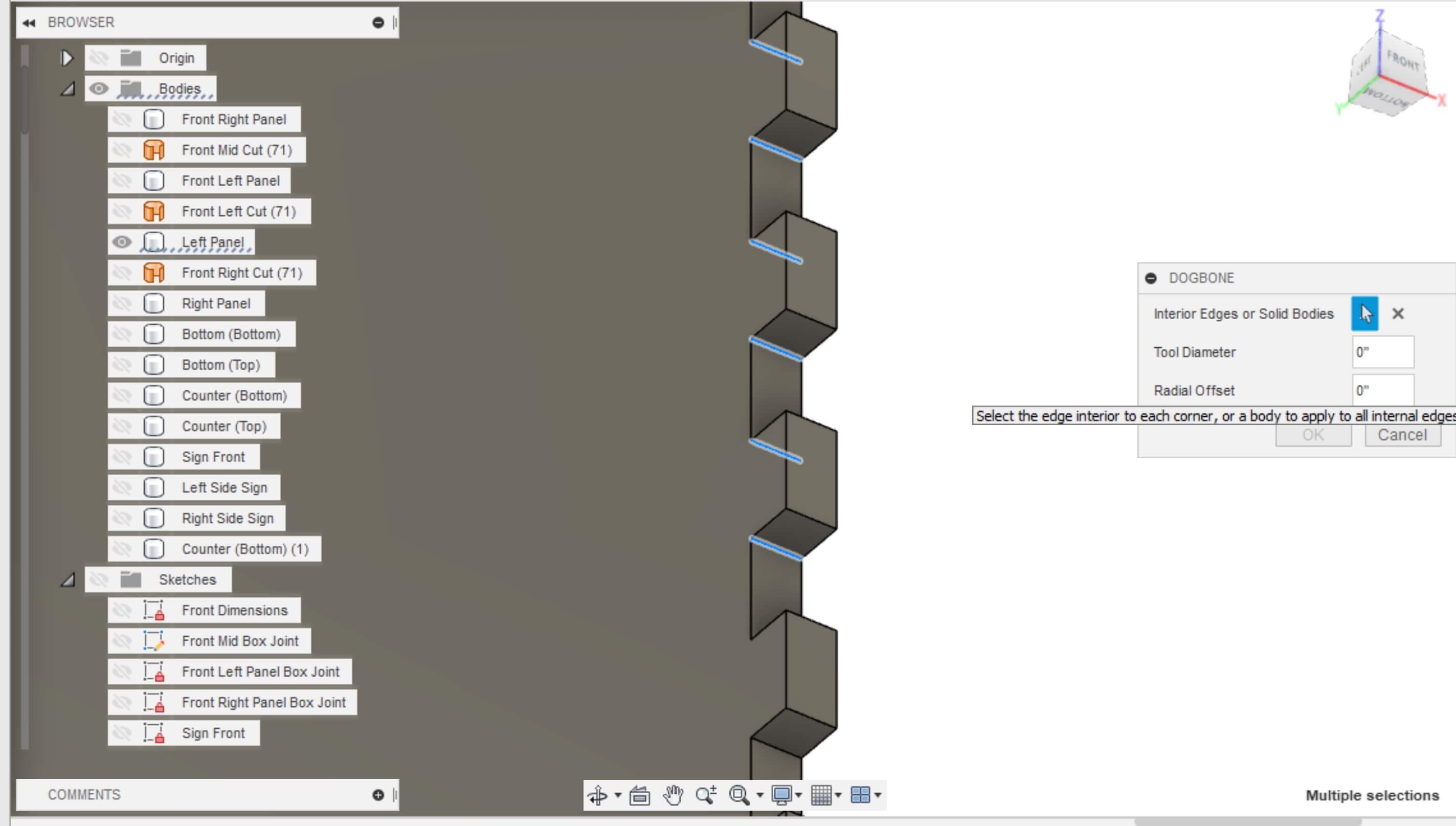
Then we had to dogbone each inner, right angle that allowed our panels to connect with 90° corners.
We installed the dogbone addin by tapnair on github that easily and automatically allows you to create dogbones on every selected corner. It bases the diameter of the dogbone based on the user's entered endmill diameter. For us, this was 0.25".
It took a little while to add the dogbones due to the amount of corners we had to select and the time it takes to calculate.
Now all of our joints were CNC compatible!
We were nervous as to how these new joints would fit together. We were especially worried about the dogbones and how much light would shine throught them.
So, we decided to make a small test of each joint to CNC.
This is also how we learned to CNC using Fusion 360! It's actually pretty easy once you go through the initial setup!
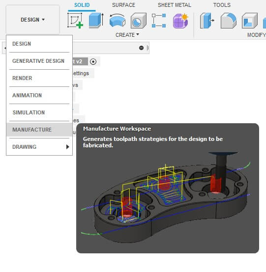
The first step is to switch over to the Manufacture Workspace
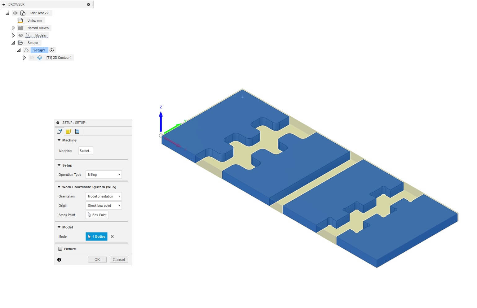
Then, under Setup, select the bodies you want to cut. Also ensure that your 'Stock Point' is set to a corner on the top of a body. This is your origin.
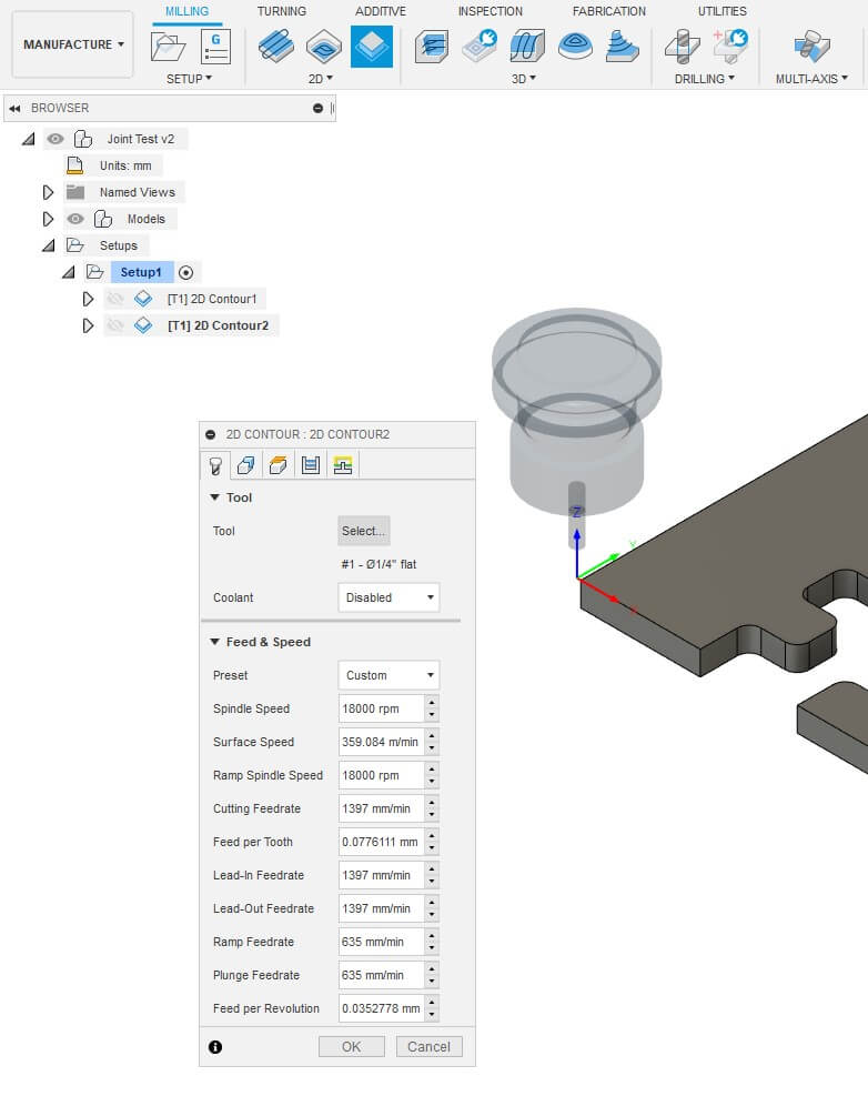
Then, at the top of Fusion 360, select the 2D Contour option and select your tool from the Tool Library.
The tool for our Axiom CNC is not in the default library of Fusion 360, so we had to import the Amana Tool Library.
After imporing the library, we had the correct 0.25" endmill in Fusion.
We can also now disable the 'Coolant' option since we are not using any form of coolant on our endmill.
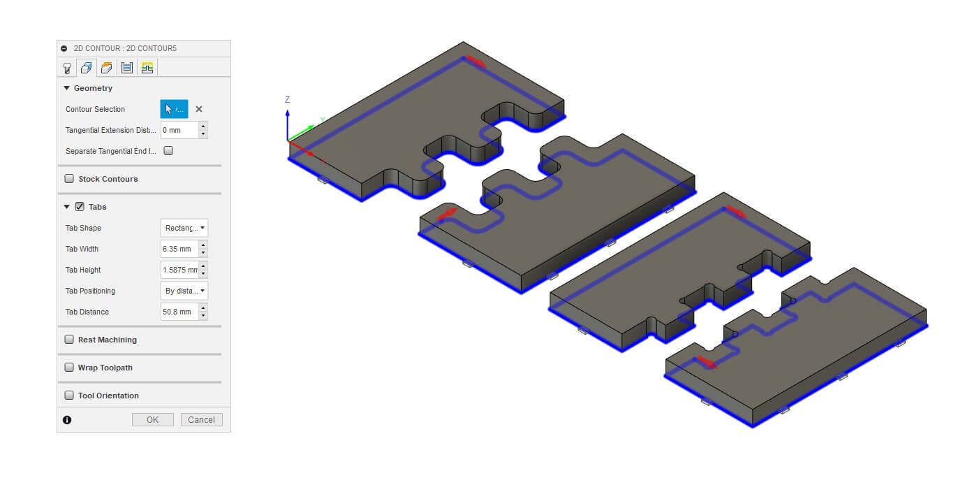
Then, under the second tab labeled 'Geometry', select the bottom path of your bodies to cut as your Countour Selection and enable 'Tabs'.
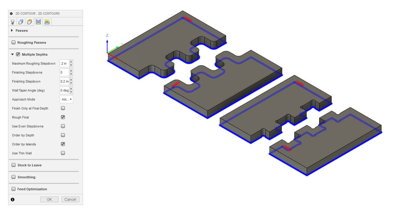
Go to the second to last tab labeled 'Passes' and enable 'Multiple Depths'. Set the Maximum Roughing Stepdown to 0.2". This will allow for 3 passes since our material is 0.5" thick.
Now the setup is done! It is always a good idea to simulate your cut to make sure everything looks like it should and the machine isn't going to destroy itself.
Notice the 3 passes? If we only chose 1 pass, there is a high chance the endmill could break due to stress.
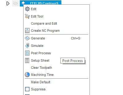
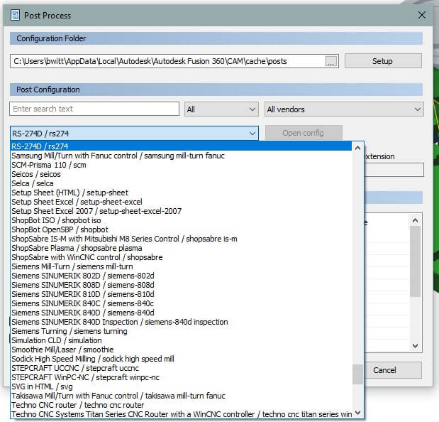
Now, right click the 2D Contour settings you genarated and select 'Post Process'.
And select your machine. At our Lab, we use the 'RS-274D / rs274' since the settings are compatible with our Axiom CNC.
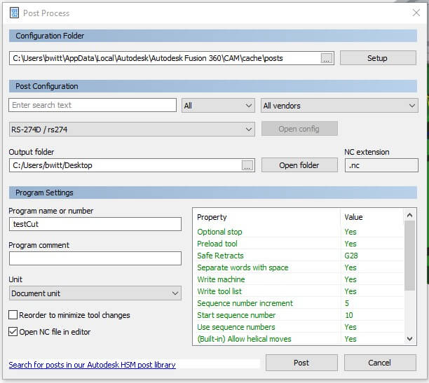
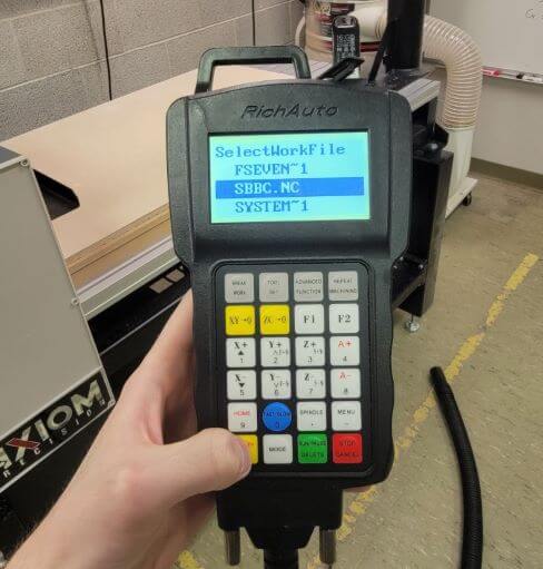
Export the file to whatever USB stick you use to upload files to your CNC and name it as you wish. We had to be clever with our names since the CNC controller screen only shows the first few letters of our file name.
If you want to view the code it genarates, you can select 'Open NC file in editor'. This will request your permission to install a 3rd Party App to read thise type of file. Note: this is optional.
After you hit 'Post', you are ready to cut!
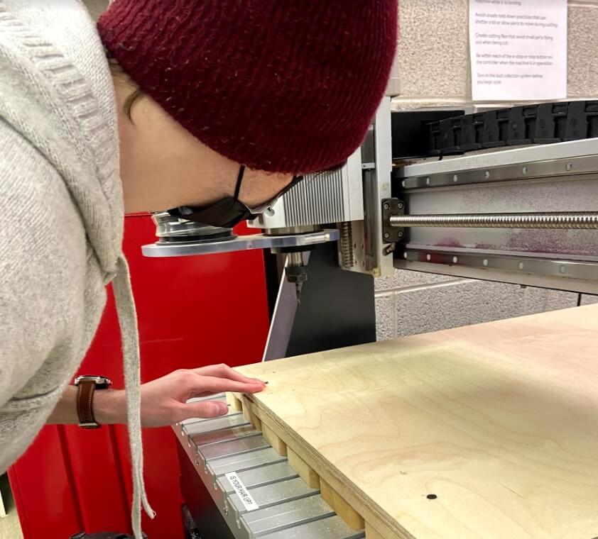
When you get to the CNC, the first step is to secure your material down as flat as possible. You also want to ensure that it will not move while being cut
We tried a combination of screws and double-sided tape at first but soon realized the tape didn't help at a large scale. So, we relied on 4 screws in each corner of the board
It is also important to ensure that your endmill never comes in contact with a screw. for the test file we were currently working with, this wasn't a worry. However, we were eventaully planning on cutting parts that spaned almost the entire size of the board. That is why I designed the panels with a 0.5" cut margin.
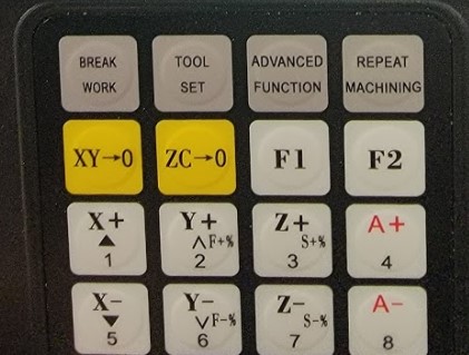
Set the origin at a point that you know allows for the endmill to avoid all screws.
Our Axiom has a really neat 'Tool Set' feature that automatically sets the z-origin by placing a connected metal plate on top the the material.
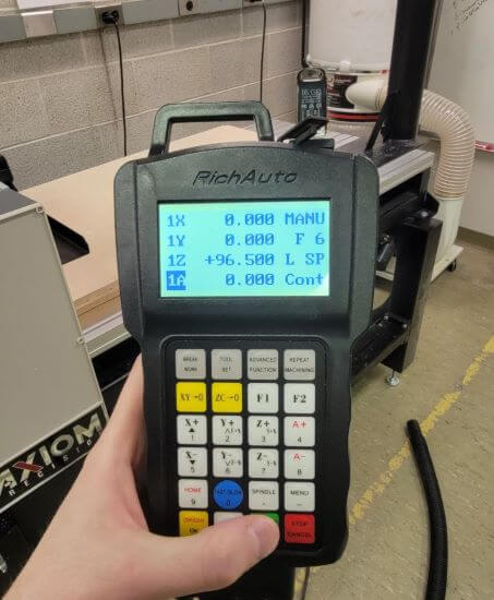
Once the origin is set, turn on the connected vaccuum and hit 'Run'.
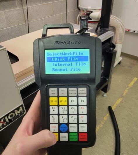
Then select UDisk File for a file on the USB
Then select the file you want to cut and hit OK to begin the countdown
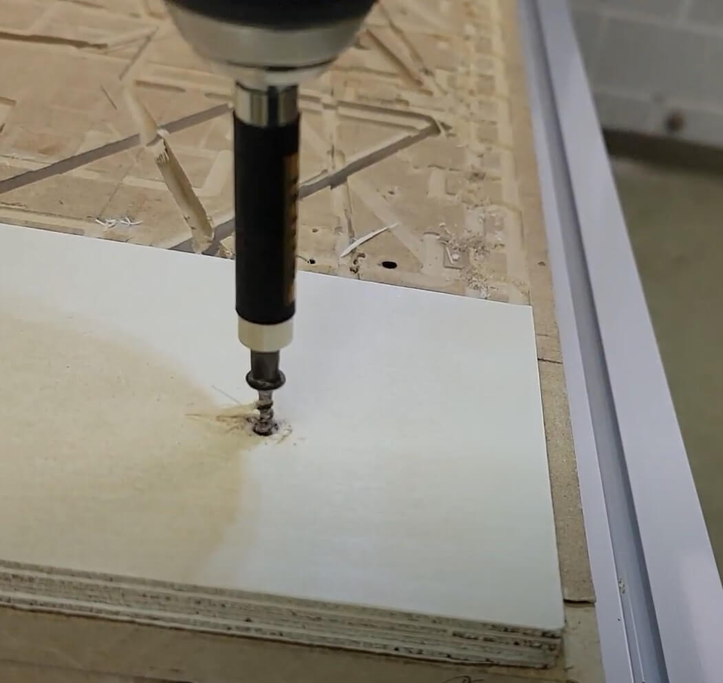
The endmill will begin to spin and the CNC will start cutting. MAKE SURE YOU ARE WEARING EYE AND EAR PROTECTION!
Here's a video of the endmill winding up.
The machine will now do exactly what the simulation in Fusion showed!
And, just like that, our test cut was completed!
I was amazed that our 1/64" clearance between the joints was actually pretty good! And the curved joints and dogbones looked absolutely perfect!
At this point, we felt confident enough to begin cutting the real thing.
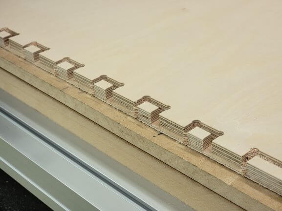
Front joint looked great!
And the corner joints looked amazing! Time for the real thing!
The process of cutting each panel was identical to how we cut the joint test above.
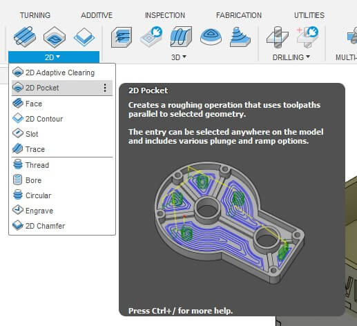
The only difference was when it came to cutting the text on the sign.
To do so, you select '2D Pocket' instead of '2D Contour'. Your Contour Selection should be set to the bottom inner edges of each letter.
Since cutting the panels followed the same steps as the joint test, I'm just going to explain some of the issues we ran into that were due to the cuts being so large.
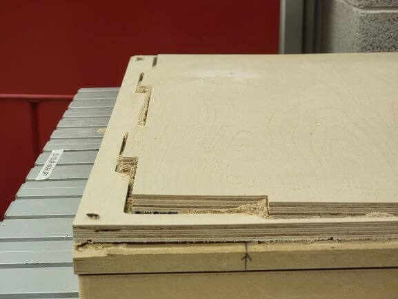
The issue that came up the most was the warped plywood. It caused many of our tabs to be useless as the wood bowed up as it was being cut.
Luckily, this didn't cause any issues when cutting, but made it harder to put everything together in the end. We also had to be super careful that the edges weren't high enough to jam the machine.
The other issue we kept running into was correctly setting the origin. We really had to eyeball where it should be to avoid hitting any screws. As I had mentioned previously, we accounted for a 1/2" cut margin, but not for the 1/4" endmill diamter.
This meant that in some places, we really only had a 1/4" margin to put the screw in...YIKES!
Luckily, we never hit a screw but you can see how close to the edge we cut. This cut even went a little off the edge!
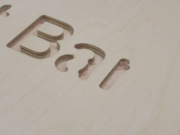
The lettering also wasn't cut correctly because our bit was too big.
In the most narrow parts, specifically the last 'r', you can see that the CNC gave up because it couldn't cut that small of a path with the current endmill.
We will go back with a smaller endmill in the future.
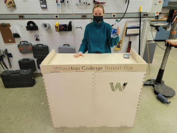
But all of this effort was definitely worth it!
Our bar came out beautiful!
Who's thirsty?
We are going to use this bar for Machine Design Week, so between now and then, Emma and I are going to stain and treat the wood. We have all of the materials to seal the cracks and make it waterproof.
We also need to glue the joints with wood glue. It is going to be a nightmare to clamp, but we'll manage!