Okay, I know, I know...My Computer-Controlled Cutting project has 3D printed components!?
But that's because I wanted my project to do something funny. I always love to complicate things more than they have to be.
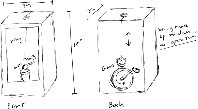
That's why I am proud to introduce what I'm calling "The Big Dipper!" The world's most convenient cookie dipper!
There were a few assignemnts this week and this is the order in which I will present them
Characterize your lasercutter's focus, power, speed, rate, kerf, joint clearance and types
Cut something on the vinylcutter
design, lasercut, and document a parametric construction kit, accounting for the lasercutter kerf, which can be assembled in multiple ways, and for extra credit include elements that aren't flat
And now, after rereading the expectations, I realize that my project doesn't fully fit the idea of a "construction kit." OOPS! At least its still cool :)
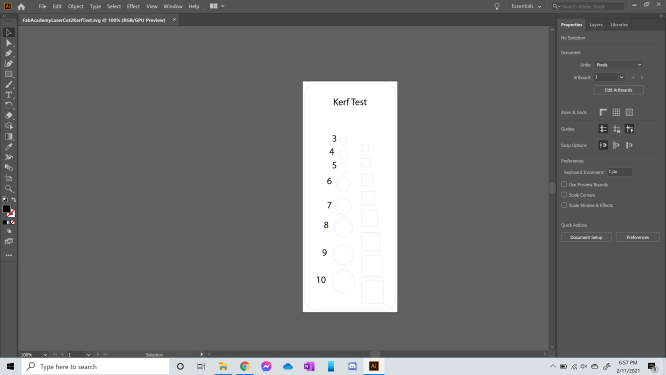
To do this, we created the design to the left in Fusion 360 and imported it to Adobe Illustrator. Fusion would not allow us to send the 1 and 2 mm holes, so we had to start at 3 mm.
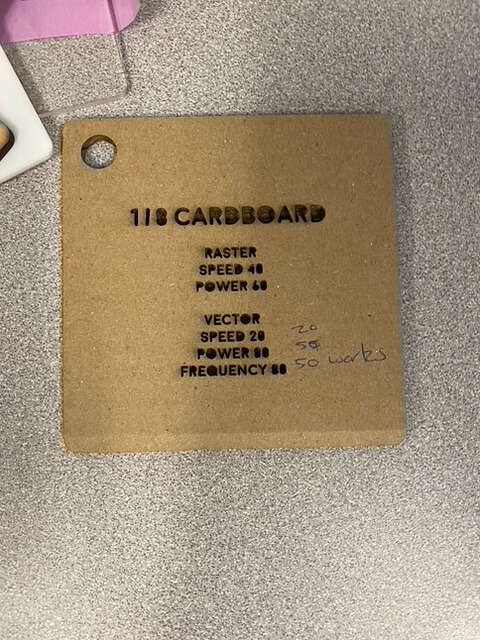
We then sent this design to our Epilog laser cutter using settings that have been proven to work on cardboard for this specific machine.
Raster: Speed = 40, Power = 60
Vector: Speed = 20, Power = 50, Frequency = 50
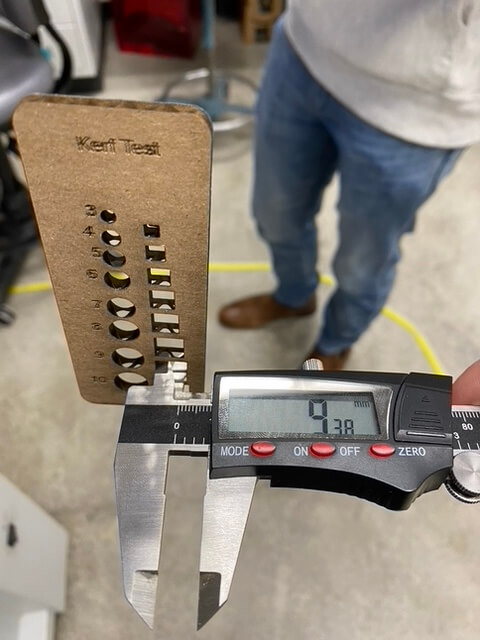
Those settings resulted in this. It was perfect! So, we used the caliper to measure each hole and calculated our kerf using the differences.
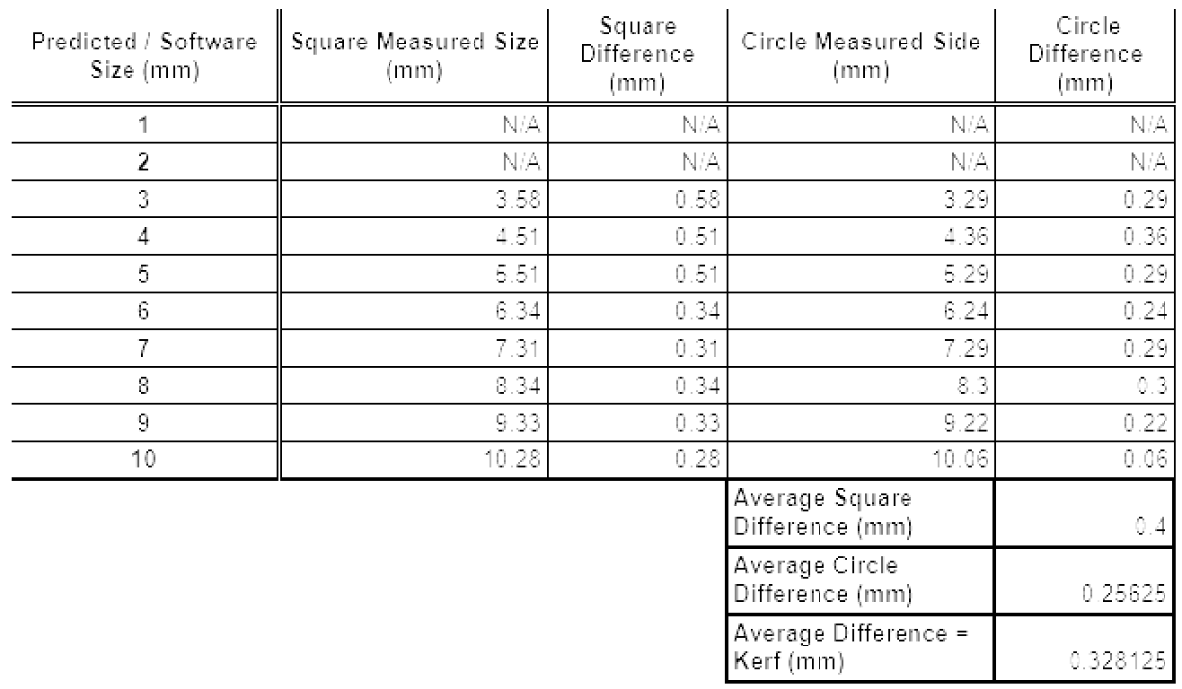
Here are the results of our kerf test.
The average kerf difference between our expected and actual measurement for our square holes was 0.40 mm and for our circular holes, it was 0.25625 mm.
We took the average of these to measure our estimated kerf which came out to be 0.328 mm. This seems a little high to me.
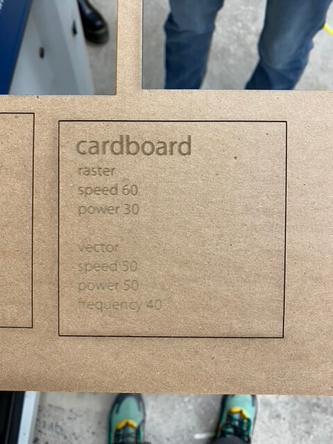
Next, we had to characterize different settings to see which ones cut cardboard the best.
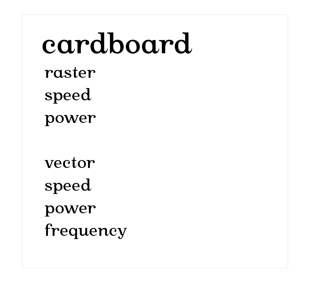
To do this, we made an Adobe Illustrator design that listed all of the settings. Each time we changed the settings of the laser cutter, we would raster these changes on the swatch
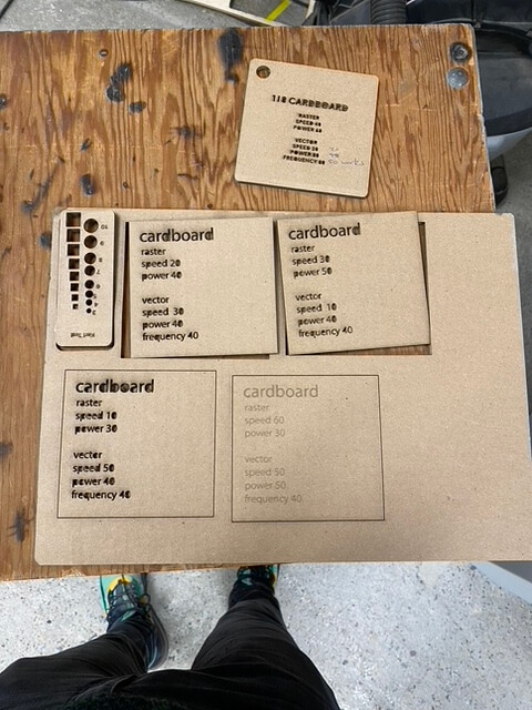
The results are below.
(top right) The best settings we tried
Raster: Speed = 30, Power = 50
Vector: Speed = 10, Power = 40, Frequency = 40
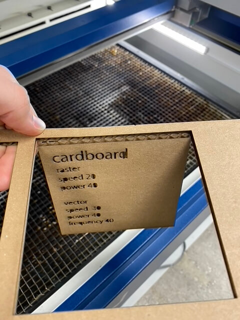
A cut that didn't quite work out
Raster: Speed = 20, Power = 40
Vector: Speed = 30, Power = 40, Frequency = 40
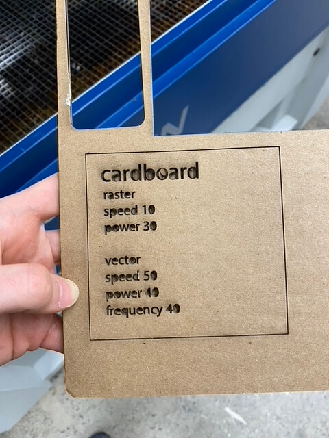
Burnt raster, didn't cut through
Raster: Speed = 10, Power = 30
Vector: Speed = 50, Power = 40, Frequency = 40
Weak settings, didn't cut through
Raster: Speed = 60, Power = 30
Vector: Speed = 50, Power = 50, Frequency = 40
Our next assignment was to cut something on the vinyl cutter.
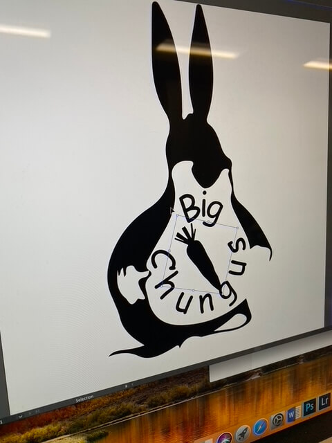
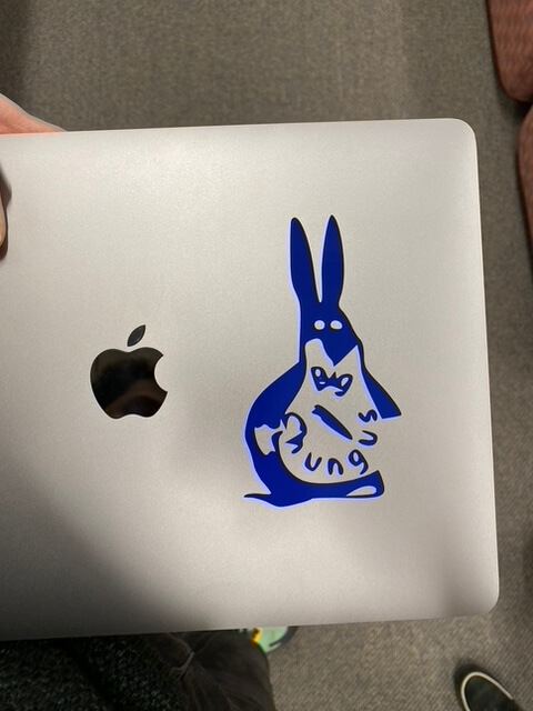
I cut two things this week. The first was a group logo that we created in 10 minutes to fit our new team name, Big Chungus.
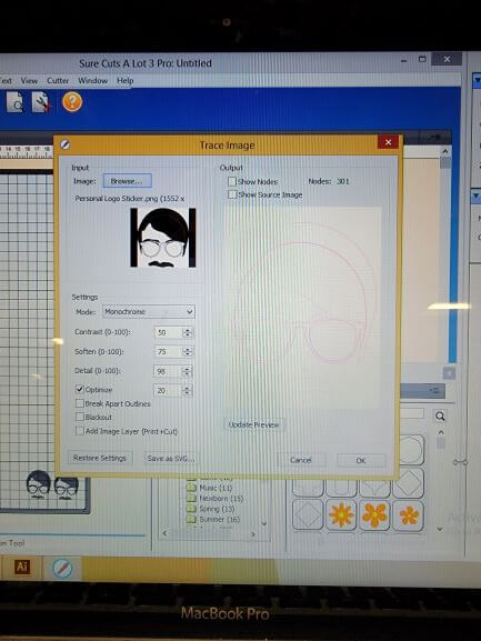
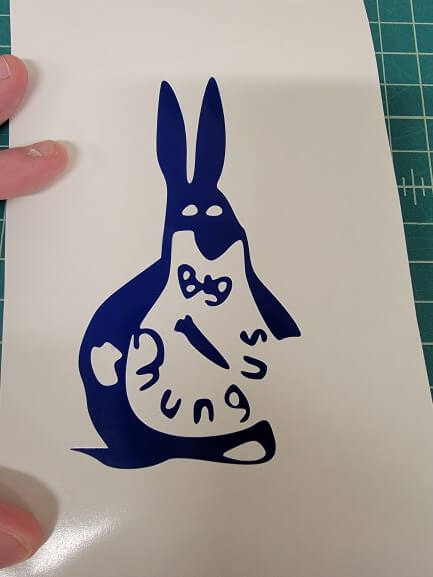
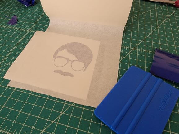
The second was a sticker of my face.
The first step was to design a sticker in Illustrator. We did this using the image trace tool. Beautiful!
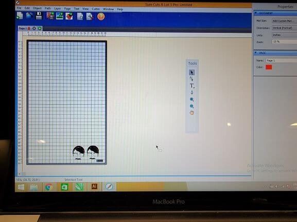
Next, we imported our design into Sure Cuts A Lot. It must be a black and white .png that is then image-traced in.
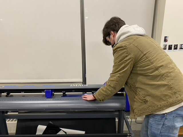
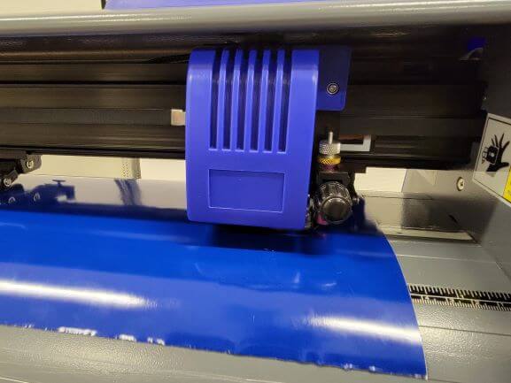
Line up the blade and clamp the sign vinyl.
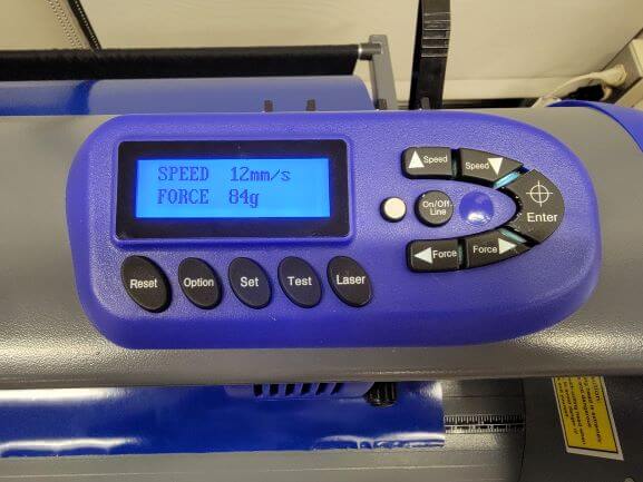
These are the settings we use to cut the sign vinyl.
Line up and resize the stickers to tell the vinyl cutter where to cut.
Weed out the parts of your sticker that shouldn't be there.
Apply the transfer tape and smooth out any air bubbles.
Apply your beautiful sticker to a surface of your choice!
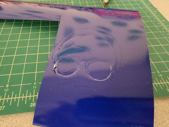
Here's one of my failed stickers.
I think the details of the glasses were too fine to cut at this size. Also, the vinyl kept bunching up becuase I do not think it was properly clamped when I cut this.
Here's what the vinyl cutter was doing when it was not properly clamped with the rollers.
Now the final task: a construction kit.
Well, I made a kit...and I constructed it. Does that count?
But in all seriousness, I had a blast making this contraption even if it is not technically what I was supposed to do.
As with most projects, the first step was to sketch my idea.
At this point, I had already decided I wanted to make an over-the-top cookie dipper but I didn't know any more than that.
I thought that I could at least make the gears out of laser-cut cardboard, but the tool I used in Fusion 360 made it hard to export the outline of the gear as a DXF.
But I decided to go for it anyways. If it worked, I would be happy...and it does!
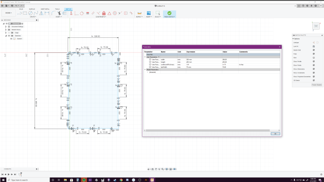
I don't want to go too in depth into the modeling process because we've already been through it a bunch. But I would like to spend a minute explaining my parametric design.
I made sure that my entire design can be changed with a few clicks of the mouse. Fusion 360 has the amazing ability to set custom parameters to use as dimentions within your design.
This means that the dimensions of every side, notch, and cutout can be changed and the model will scale accordingly.
This is especially useful for features such as the cardboard's thickness. I wasn't sure what thickness of cardboard I would be using, so I set it to an arbitrary value. When I learned that the
cardboard is 1/8" thick, I was able to plug in that value as a parameter and watch as the grooves changed size to accomodate it.
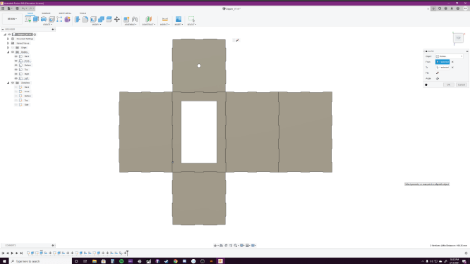
Here's me changing the height parameter of one side of the box. Notice how the grooves remain the same size and are evenly dispursed along the entire edge before and after the change.
It is important to note that Fusion dislikes when you change the parameter by too large of a value. I could only change by a miximum of 50 mm at a time before my design would break.
This is a known issue that the Fusion developers are working on.
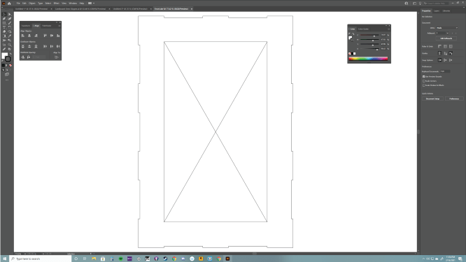
I completed my design and Fusion and exported each separate sketch as a DXF file.
The DXFs are then imported into Illustrator where the stroke weight is changed to 0.01 mm. Make sure the units are 1 : 1 mm.
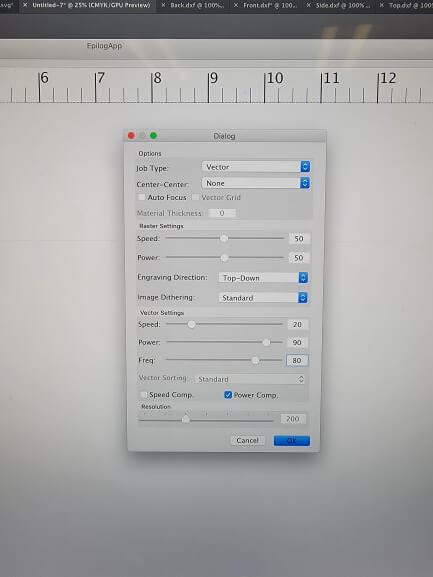
Here are the settings I used to laser cut my design.
Raster (doesn't matter because I am only cutting): Speed = 50, Power = 50
Vector: Speed = 20, Power = 90, Freq = 80
Here's the laser cutter cutting out my box. The cardboard was warped, so I had to hold it down with duct tape and heavy objects.
You can see a weight on the right of the cardboard.
#OddlySatisfying
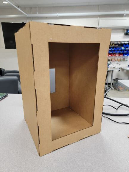
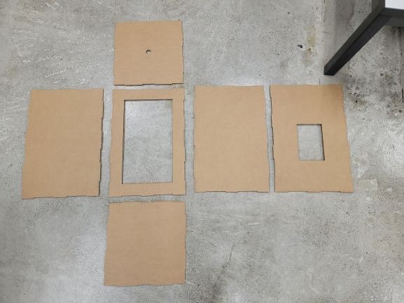
Here's what the cardboard looked like after being cut.
Here you can see just how bad the bend in my cardboard was. I tried to place it under a heavy object for a day, but that did nothing.
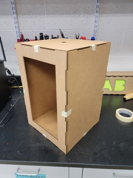
So I decided to tape it together because it wouldn't stay together without it.
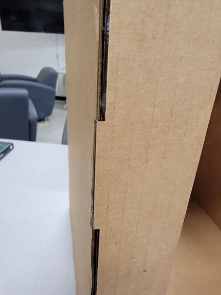
And here is a close-up of one of my joints.
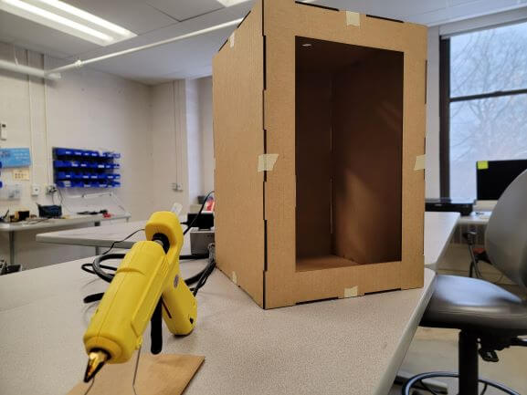
And here's where we stray away from the assignment.
I decided to hot glue my kit together because it absolutely would not hold without that or tape.
But sometimes, its okay to need a little extra support!
I would like to quickly explain why the glue and tape was needed to hold everything together. To put it simply, I was lazy and didn't account for kerf in my design. I truly did not think
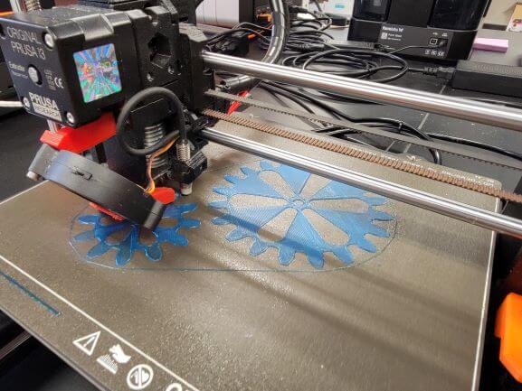
I 3D printed the components that I modeled.
Here's the back-plate printing.
Now, who wants cookies?
I would like to quickly explain why the glue and tape was needed to hold everything together. To put it simply, I was lazy and didn't account for kerf in my design. I truly did not think that it would affect anything, especially with a soft material like carboard.
But, as I proved above, the joints were actually too loose because of this. Thus, my project was not actually "press-fit" Perhaps if I accounted for kerf, the joints would be tighter and friction would probably hold everything together. But, by the time I realized this, it was too late!
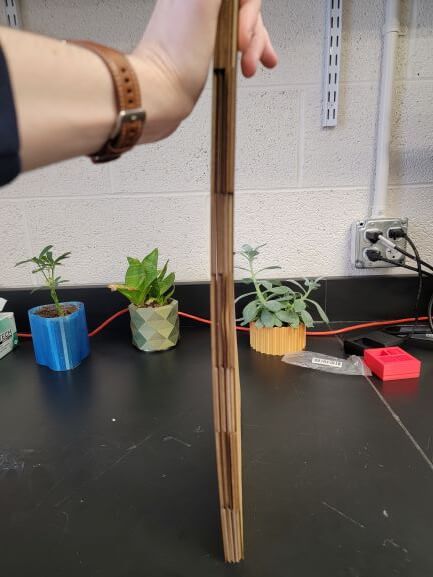
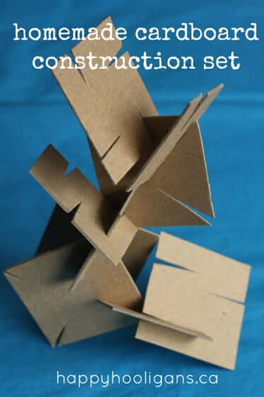
I also believe that making a box was not my smartest idea. I should've followed the assignment more closely and made an actual contruction kit. That way, the joints could be deeper than 1/8" and the cardboard could go together in a more structurally sound way.
I should've created a press-fit kit like the one shown here. Then, it would've actually been a construction kit, not just a box. The joint structure they are using in this example would've been much stronger than the finger joint's I used. I didn't account for the bend of the cardboard, so using large sheets proved to be another major issue in my design.
All of these issues could've been avoided had I followed the assignment closer. But, I still had a ton of fun, got experience with parametric design and laser cutting, and learned how kerf can make or break a project!