Group: Test the design rules for your 3D printer(s)
Individual: Design and 3D print an object (small, few cm3, limited by printer time) that could not be made subtractively and 3D scan an object (and optionally print it)
Please enjoy this amazing video which took me way to long to put together.
It shows the process of designing and printing my Plinko Board!
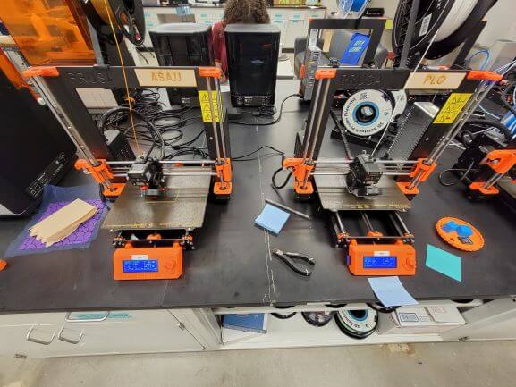
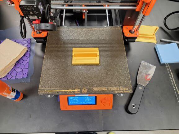
We first had to complete the group assignment using the 3D printers in our lab. We have Prusa printers and the model that I used most for this assignment was the MK3. I also commonly use the MK3S.
We also have a couple of SLA 3D printers that I have not yet used. The difference between a regular 3D printer and an SLA printer is that a 3D printer works by extruding plastic filament through a heated nozzle whereas and SLA 3D printer uses resin that is hardened by a reaction to light.
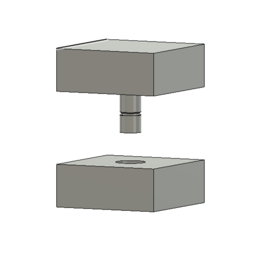
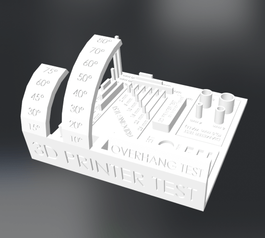
To test the capabilities of our printer, we used a couple of prints. The first was a set of boxes where one had a peg and a groove that is supposed to fit in a hole on the other one with a ridge to lock it in place.
After printing, we noticed that the connection was very loose. This is because of the nature of the plastic (PLA) that is used to print. When it is extruded at a high temperature, it then settles and can expand or contract.
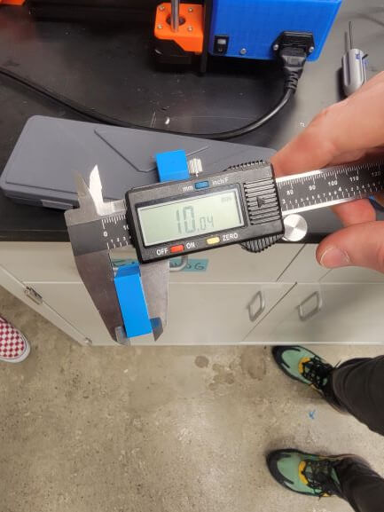
This side is supposed to measure 10mm. As you can see, it is actually 10.04mm. The margin of error is consistantly plus or minus 0.05mm.
Here, you can see a measurement that was designed to be 1" and was printed exactly at 1".
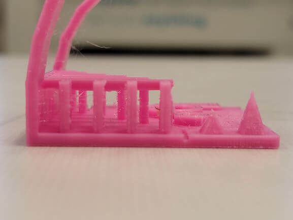
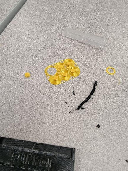
For a second test, we decided to print a model we found on Thingiverse by the author, Majda107.
We attempted to print this twice, and both times the print failed. Other groups had similar test prints that were successful, so we're not quite sure why ours failed. We used some already-printed units as tests.
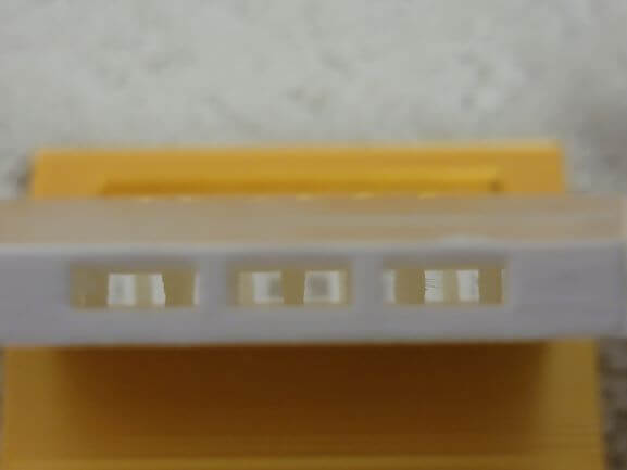
I was especially suprised at the bridging capabilities of our printers.
I had no idea that 3D printers were able to bridge between two points until seeing it for myself.
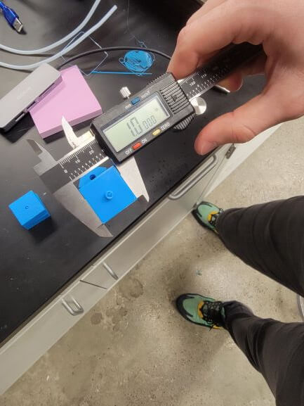
We also took measurements of different parts of the unit and noticed the same error margin we noticed in our original test.
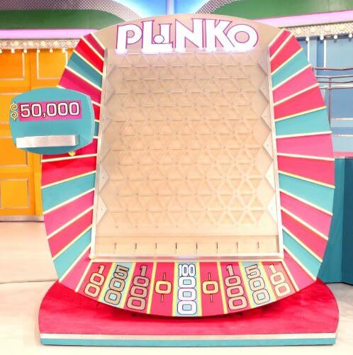
And with that, I was ready to begin my project. I took me a while to come up with what I could make, but I evenually decided to make a miniature Plinko Board from The Price is Right!
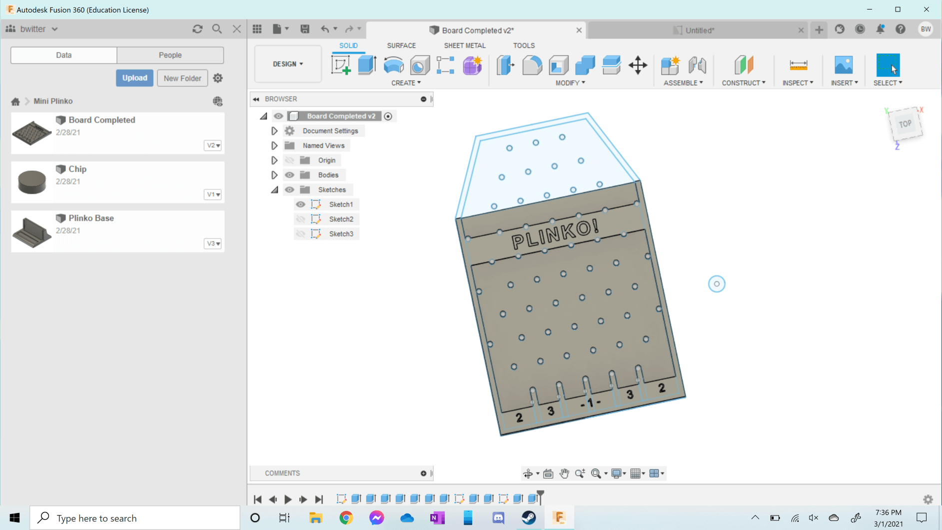
I created my own design in Fusion 360, and it actually took two versions to create a working game.
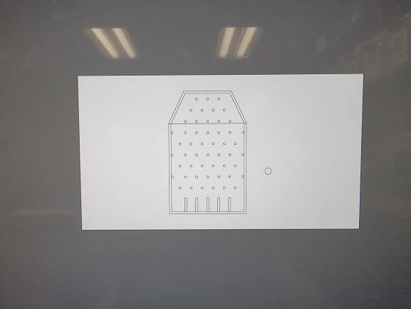
Here is my design. My first print was just a rectangle that had pockets in the bottom and a bridge across the top to satisfy the requirement of being impossible to make using subtractive methods.
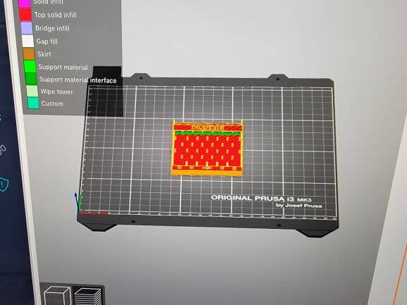
I was made aware, however, that by simply roating my model and using the right bit, it could be made subtractively. So, I added a "funnel" full of pegs with three openings on the top, which can be seen in blue.
After finishing the model in Fusion, the next step is to export it as a .stl and import the .stl into PrusaSlicer.
PrusaSlicer is where you select your printer type and settings to generate the G-Code that the printer understands. The G-Code is loaded onto an SD card and loaded in the printer.
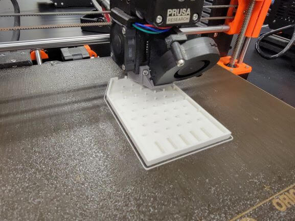
My original print
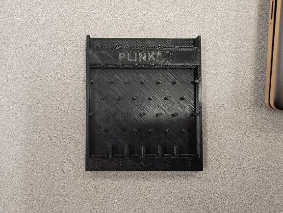
My final print
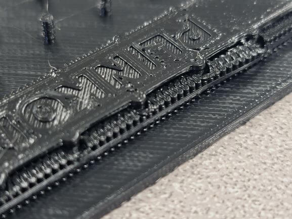
I also decided to print my first model with supports because I was not confident about how well it would handle the bridging across the top pegs.
This actually rendered my print useless as I couldn't physically remove all of the supports and they stopped the chips from being able to drop.
After my board was printed, I noticed that the chips kept falling out of the front whenever they hit a peg. To fix this, I decided to laser cut a small piece of clear acryllic to glue to the front.
To the right is the DXF of the sketch from Fusion 360. I timmed it so that it was only the outline and then laser cut it.
I also designed and printed a base
And some chips. Both the base and chips could be made subtractively. I printed these with a brim becuase they are so tiny.
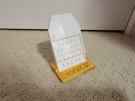
I put everything together and it worked! Make sure to watch the YouTube video at the top of this page, too!
Top view of the inside of the "funnel"
And here's the final product fully assembled
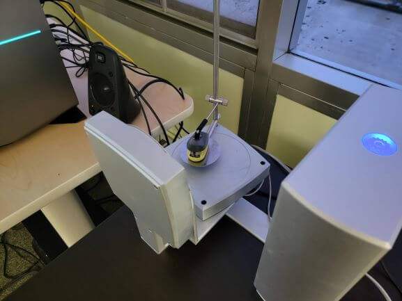
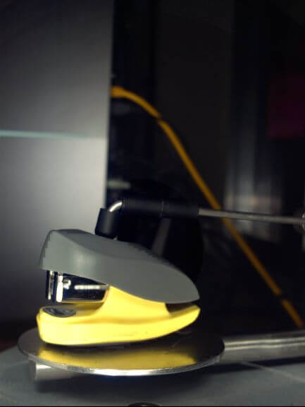
Next, it was time to try out some 3D scanners. I decided to scan my mini stapler.
We have a stationary 3D scanner at Wheaton, but it's a little old. I also was confused by the decision to have such a tall metal arm because as the tray rotates with the object, the arm scrapes the machine.
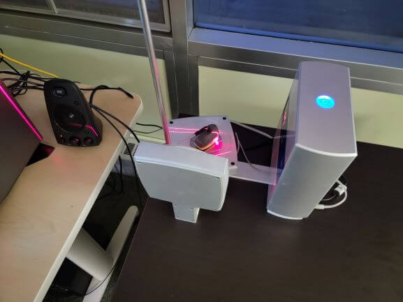
Our scanner works by shooting lasers at the item to scan and sensing the depth. It also takes pictures and uses those images to map color and texture.
To get all angles of the item, the tray rotates and that's why the arm to hold it in place is neccessary. Like I said, there is no reason for it to be as tall as it is.
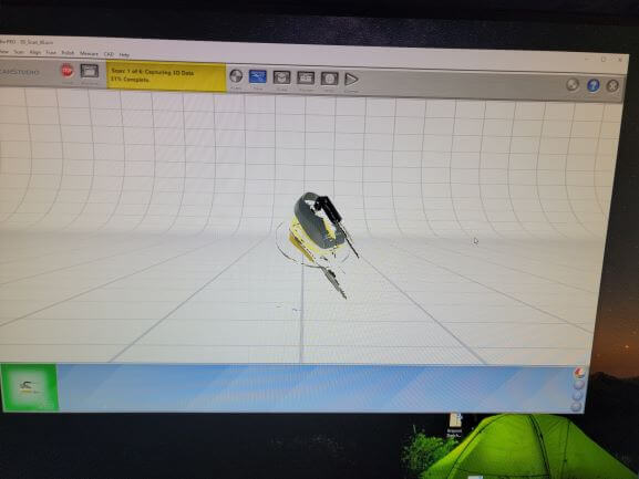
We use a software called ScanStudio. Here's what it looks like while scanning.
And here's one of the pictures the unit took
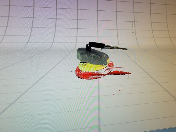
The scan took around 30 minutes. This was after two scanning passes at medium quality.
I had to spend another 15 minutes or so to trim the base plate and arm from the model.
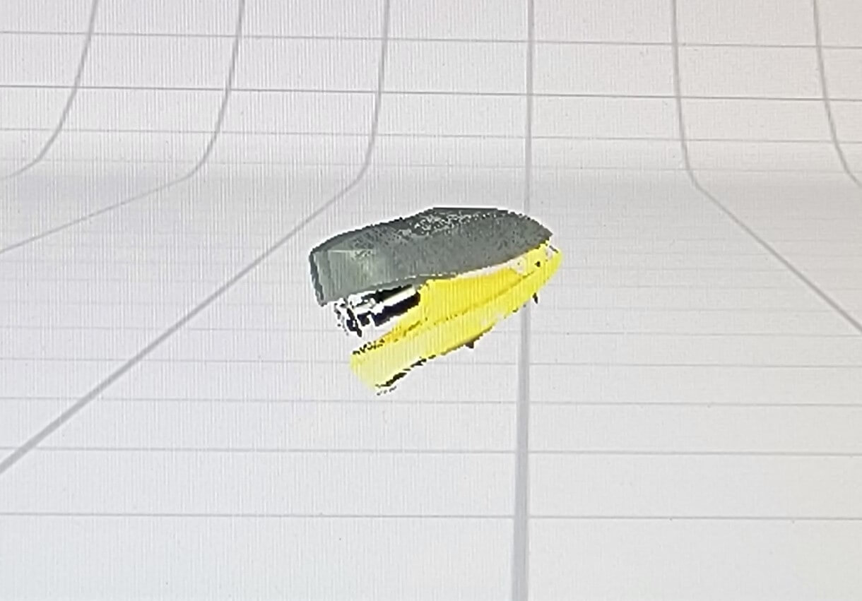
I was then able to export my scan as a .stl file. It didn't come out great but that's mostly because I used medium settings to save on time. The scanner also struggles with any reflective surface like the chrome on the stapler. That's why it appears empty im many places.