design a machine that includes mechanism+actuation+automation
build the mechanical parts and operate it manually
document the group project and your individual contribution
actuate and automate your machine
document the group project and your individual contribution
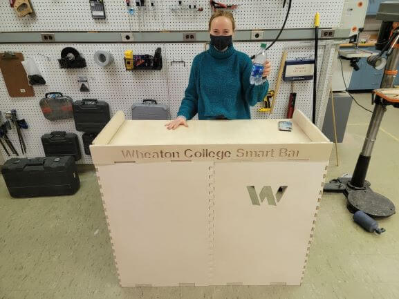
In order to complete this assignement, we split the class into 3 teams: Design, Plumbing, and Electronics. Our ultimate goal was to create a Smart Bar that could mix drinks of the user's choice. Each group's documentation has its own section below.
The design team consists of Rushil Bhatia, Brandon Witter, and Emma Yount.
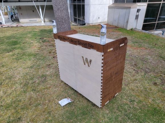
The first step was to design and cut the bar counter. Emma and Brandon accomplished this during Computer-Controlled Machining Week. Check out
Emma's page here
and Brandon's page here
to view the steps that created the counter shown above!
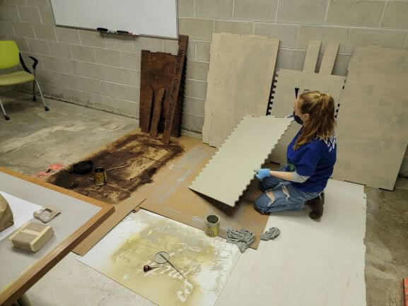
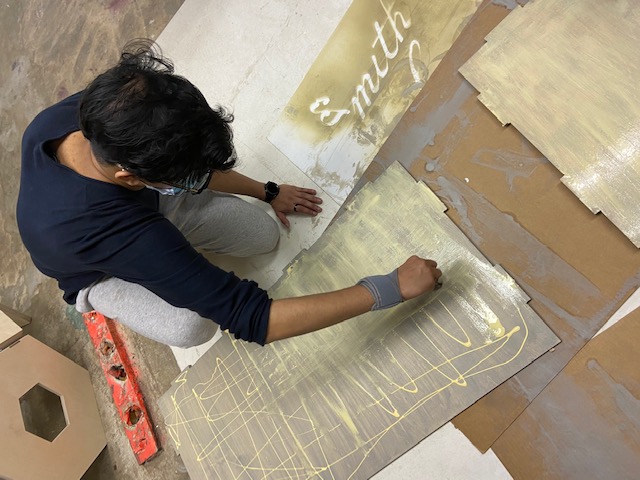
We began this week's assignment by using sanding blocks to sand each piece of wood that we cut. We also used loose sandpaper to get the frills on the edges of the joints.
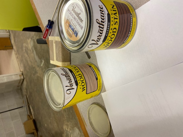
Then we began the staining process. We wanted to get a cool two-toned pattern along the joints so we chose a dark chestnut stain for the sides and a hazelwood stain for the front. This process took a couple of days since we had to apply 2 coats.
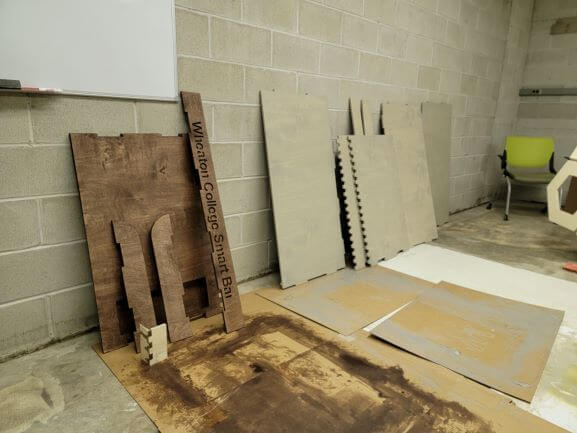
Here's what the wood looked like once it was fully stained and dry!
We had a little bit of trouble with the hazelwood stain. It seemed to contain a gunky, gray paint that was tough to scrape off the bottom when stirring. It was also a lot more gray than we anticiapted, but it still works very well with the chestnut!
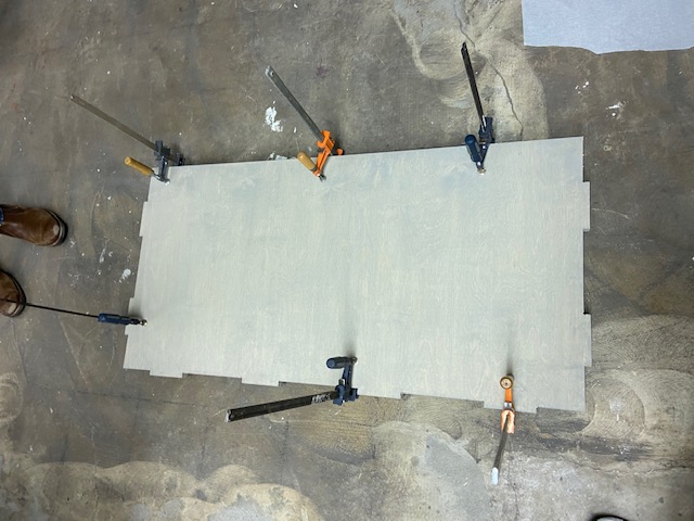
Once the stain was completely dry, we used wood glue to hold everything together.
We applied wood glue to both surfaces of everything we were gluing together and spread it evenly with a paintbrush. Clamping was easy for flat pieces, but not for the corner joints.
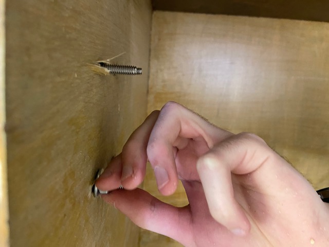
For this reason, we decided to use glue on the joints and also screws for extra support.
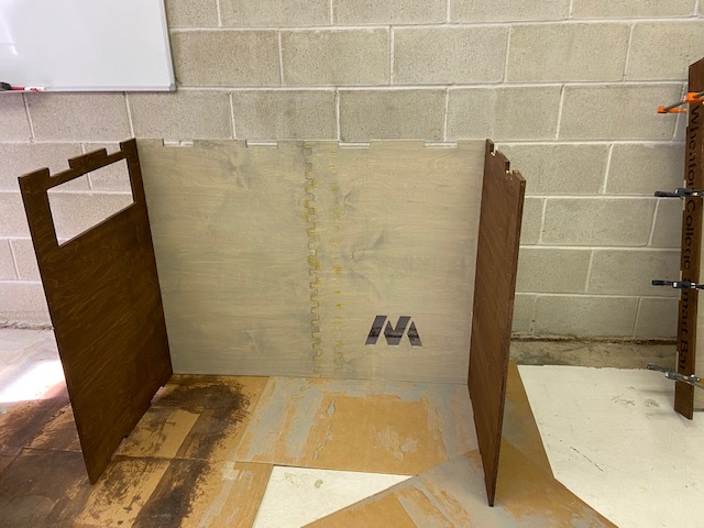
We glued the bottom of the counter in and ensured a tight fit with our improvised rubber mallet. Then we added screws and let the glue dry.
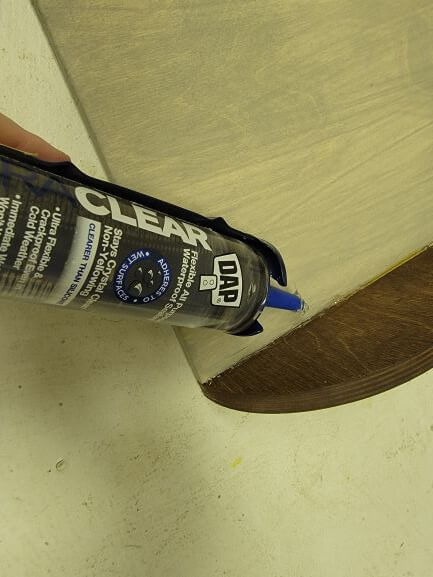
After the glue dried, we applied a clear, silicon caulk along all of the interior edges so liquids couldn't escape in case of a spill.
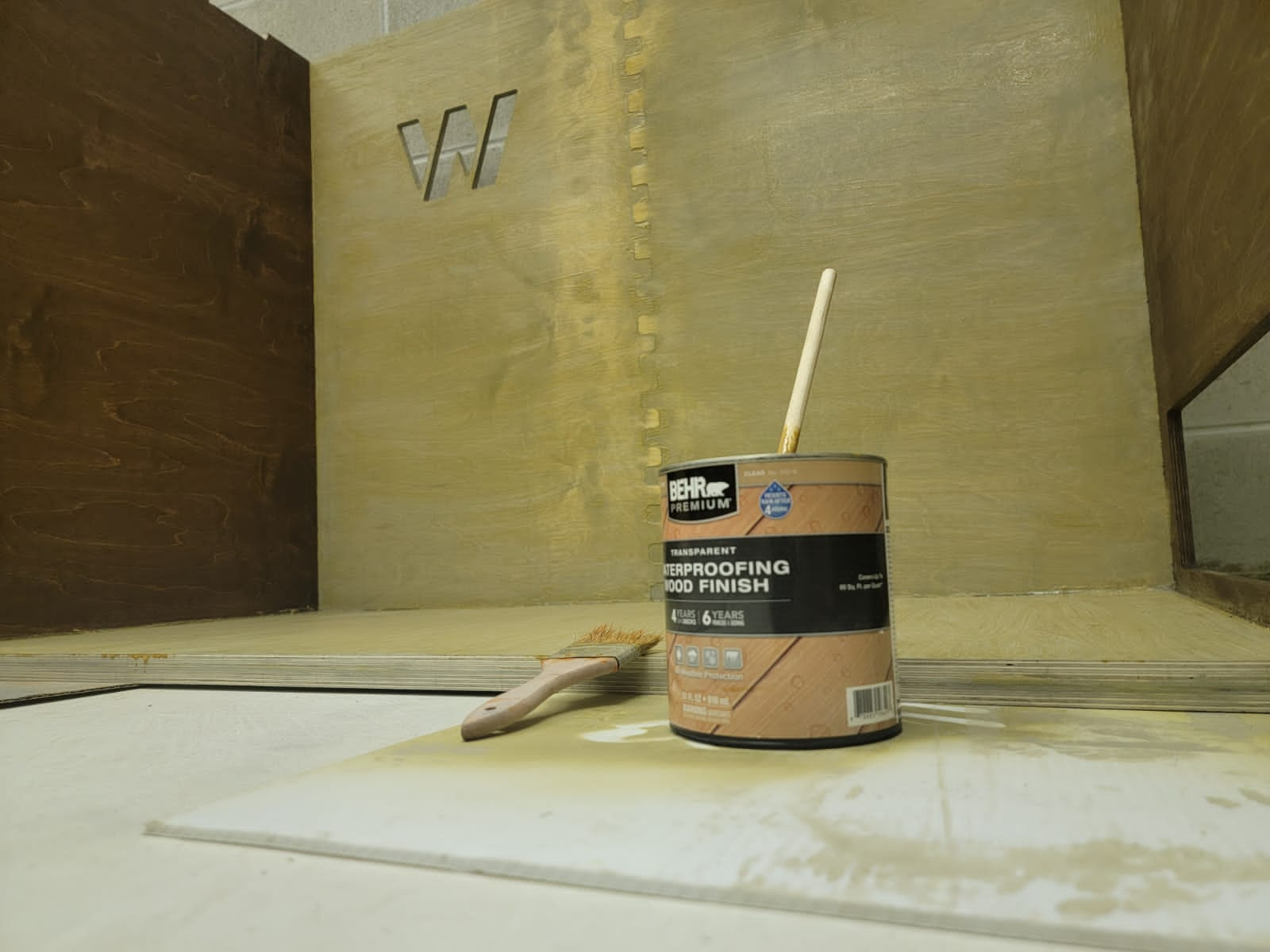
We also purchased a "transparent" waterproofing treatment for wood that was not transparent over the hazelwood stain. Luckily, we started on the interior so we were able to treat the exterior with something else.
We then attached the wheels to the base using 1/4" bolts, nuts, and washers.
This allowed us to roll the bar across campus to a spot where we new that no one was going to touch it. We sprayed it using an all-purpose, weatherproof clearcoat. It gave our bar a pretty nice sheen and really brought out the colors of the stain!
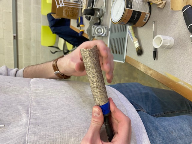
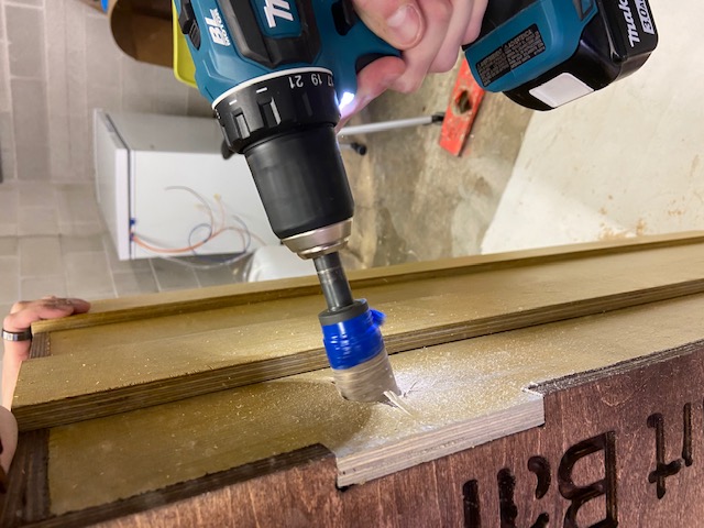
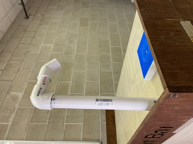
We also had to attach a faucet for the plumbing tubes to run through.
We had purchased a nice silver one, but decided that a PVC one is fine for the time being.
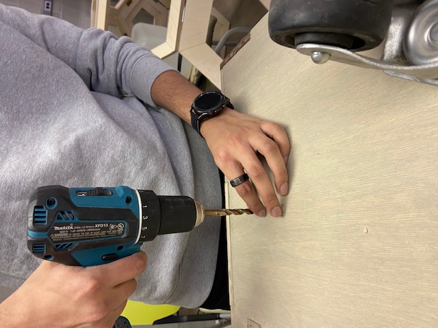
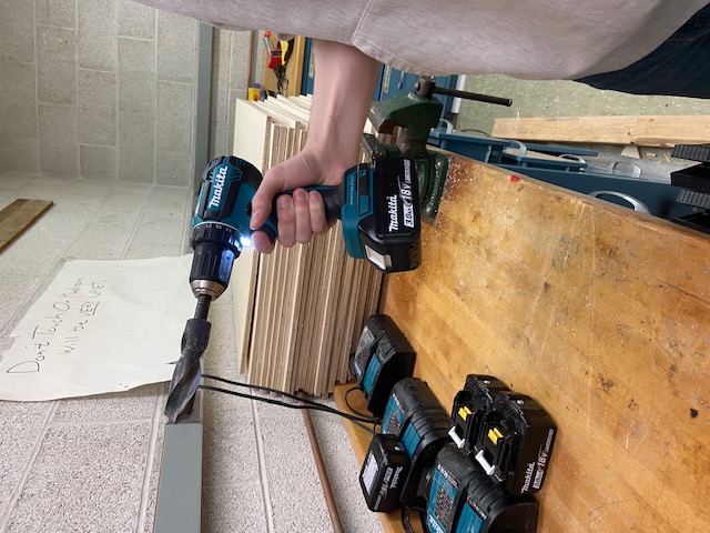
We had to drill a hole wide enough to support the PVC so we used the biggest drill bit we had. This created a hole that was a tiny bit too small, so we decided to tape sandpaper to the bit and sand the hole down. If it looks stupid but it works, it ain't stupid!
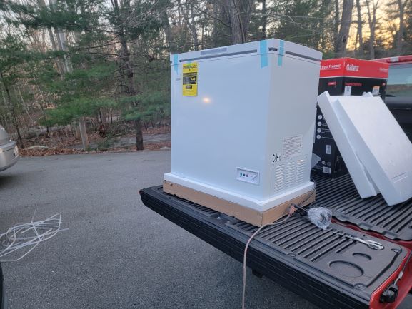
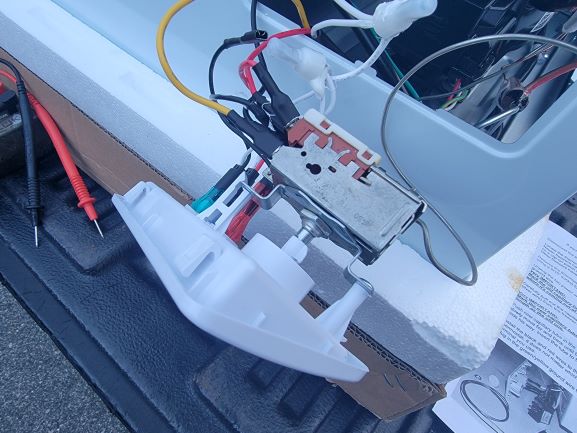
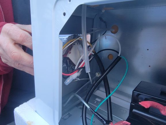
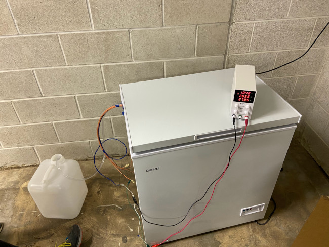
We decided the best way to chill our drinks was to convert a 5.0 cu ft chest freezer into a refrigerator.
It really wasn't dificult at all! It involved removing the venting and front panels, replacing the freezer thermostat with a refrigerator one from
this coversion kit,
and running the new probe where the old one used to be in the capillary tube.
Lastly, we had to 3D print and laser cut a couple components to integrate the other teams' work.
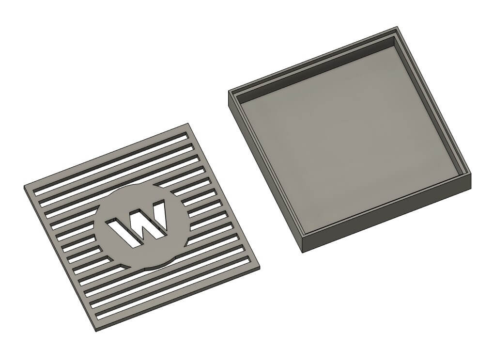
We firstly printed a spill catcher in case a cup overflows while it is being filled.
We also lasercut a sheet of frosted acrylic to go behind the Wheaton logo to shine lights through.
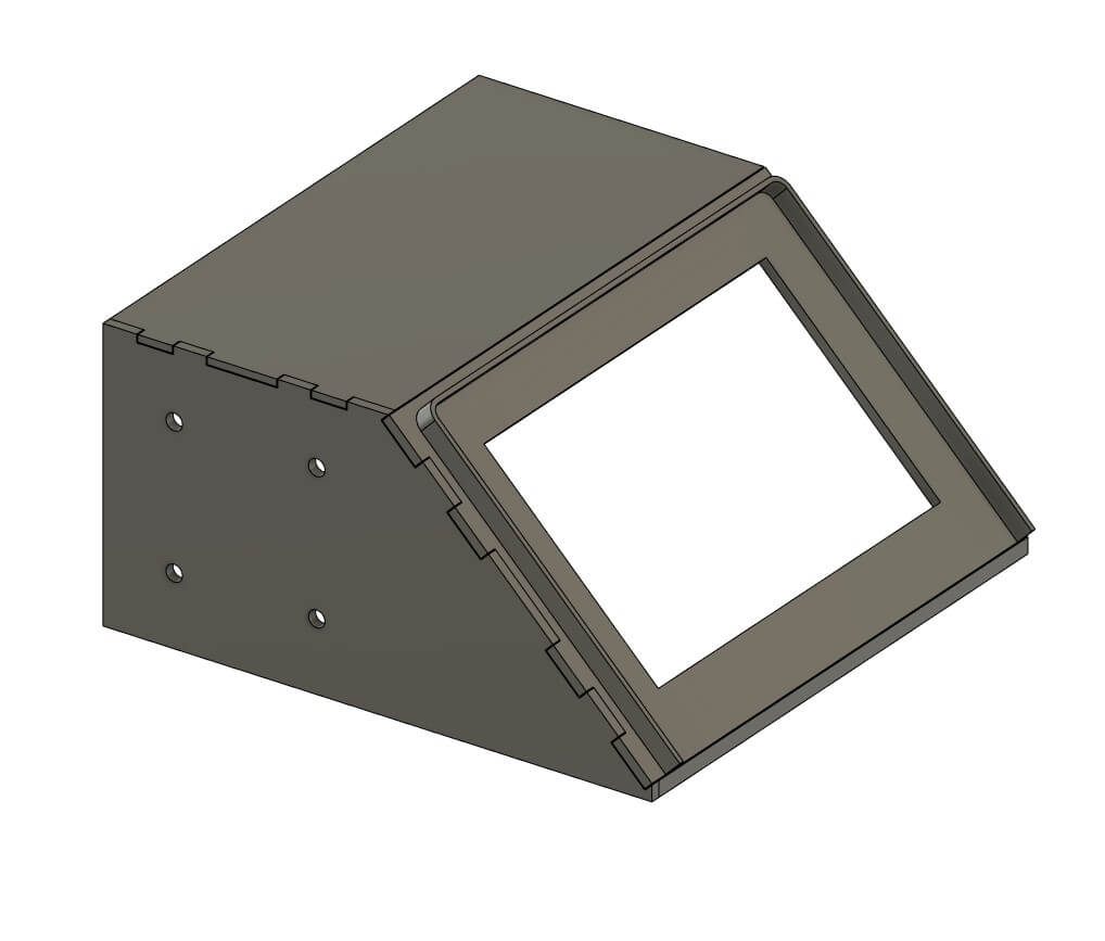
And lastly, we 3D printed a mechanism to hold the control screen underneath the counter. This seems a little too flimsy, so we are going to redesign this soon.
This first section is about programming the user interface using a Raspberry Pi.
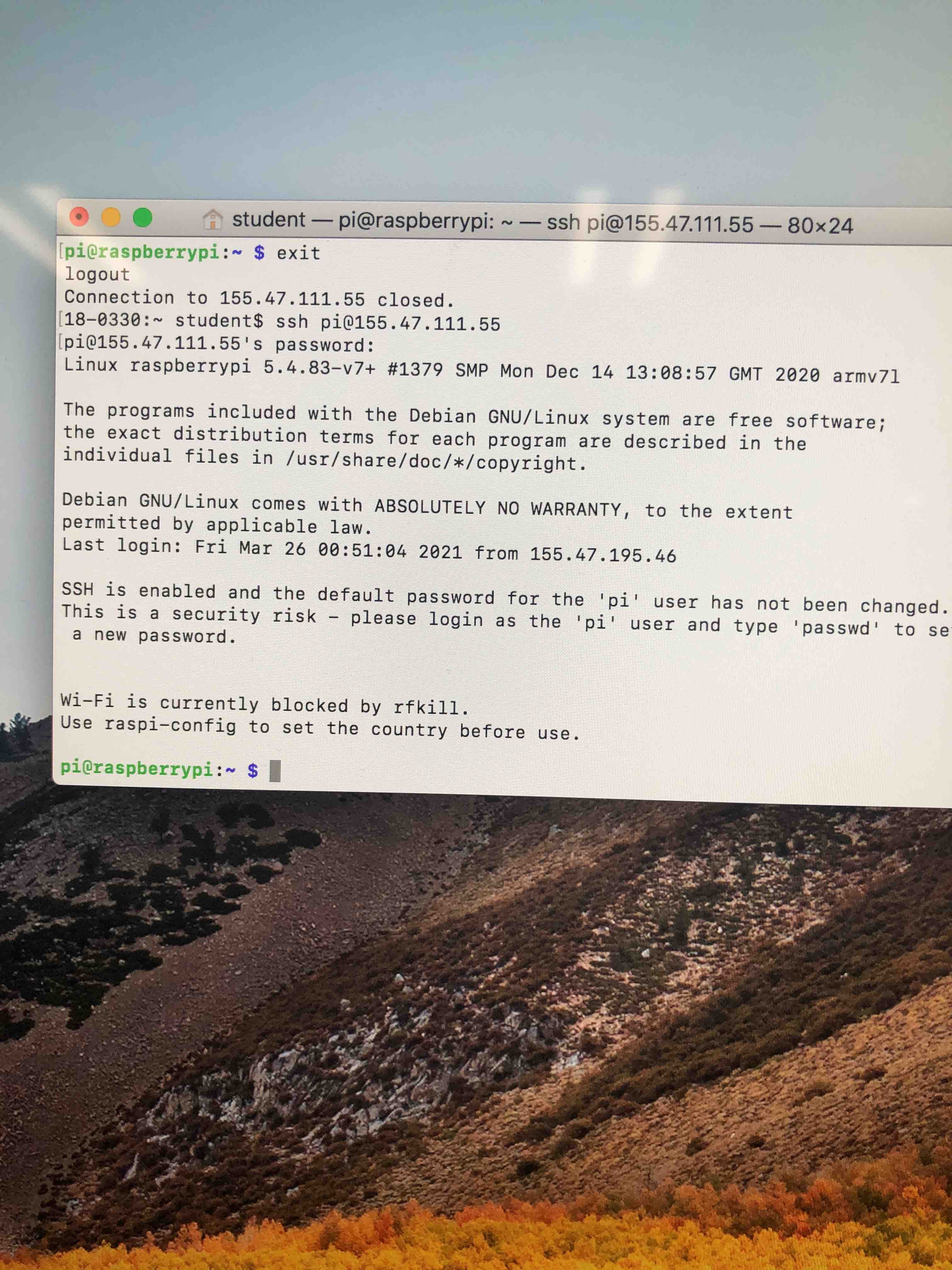
The task of programming the Raspberry Pi began by setting up the Pi to be accessed via SSH (secure shell). This made the process of running code and setting up the Pi far easier since it could be done from the larger iMac in the lab. We followed online tutorials, and collaborating with eachother.
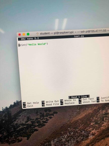
In order to test the Raspberry Pi and see if we had correctly shelled into the Pi, we created a small Hello World file using "nano test.py", which ended up working! Seeing that we were able to shell into the pi and had correctly booted the pi, we then began to work with Rpi.GPIO in order to set up the GPIO pins (General Purpose Input/Output) for the valves and pump.
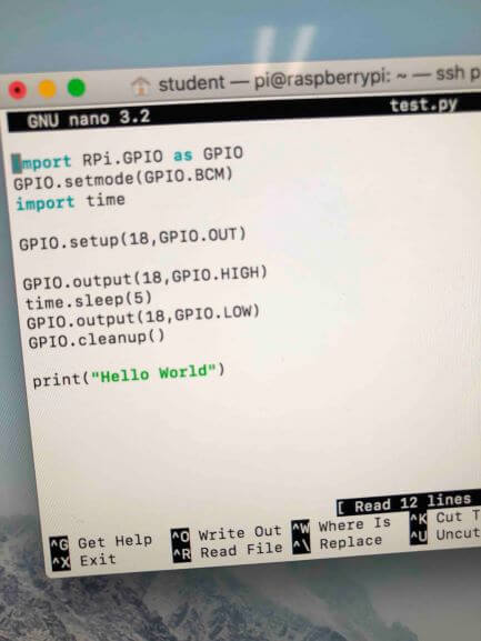
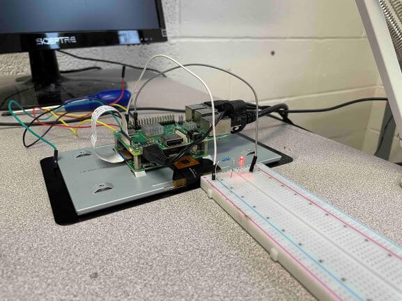
To test our ability to use the Rpi library to power the GPIO pins of the Pi, we edited our hello world file to include the above lines of code. We connected GPIO pin 18 to a breadboard at first with a resistor and an LED in order to see if our code was working correctly.
Once we were able to get the LED to light up by setting up the "GPIO.output(18,GPIO.HIGH)" code to work with the LED, we instead plugged in the pump to see if it would work with that too.
This worked too! The only thing left to check was the solonoid valve, and to see if the same setup would work with the valve.
THIS WORKED TOO! Since the Raspberry Pi was now able to be coded in Python to power the valves and pump through the GPIO pins, the next step was to create the code for the project.
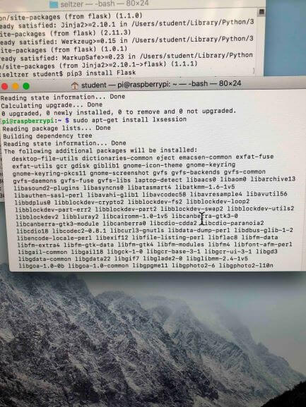
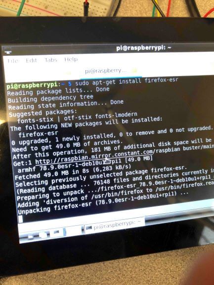
We split off to get (1) the Raspberry Pi to correctly boot into GUI mode so that it booted into the desktop and (2) start design on the front-end and back-end for the app. The app used an SQL backend and a Python/HTML/JavaScript front-end with Flask. To get the Pi to boot properly, many libraries had to be installed, and hours of troubleshooting began.
After a number of packages and libraries were installed, and using "raspi-config" to try to change the keyboard from EU to US, we finally got the Pi to boot into GUI and started to get the Pi ready for the App.
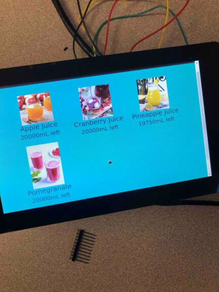
We figured out that Chromium Browser (Raspberry Pi's favorite browser) would allow us to use the touchscreen to interact with the app and the finished product worked out beautifully. The user is able to interact directly with the screen to select a drink and their desired volume that they want dispensed. To check the system before installing it, we again used a breadboard and LEDs with resistors in order to see if the GPIO pins would work.
This next section is about programming speakers and LEDs.
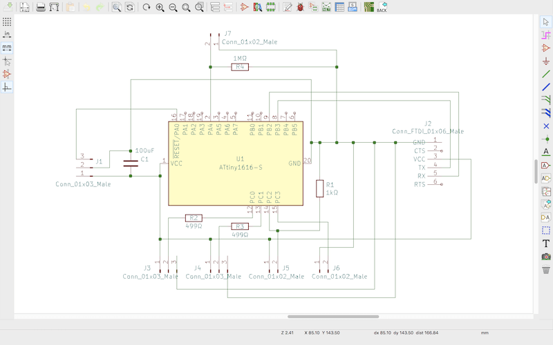
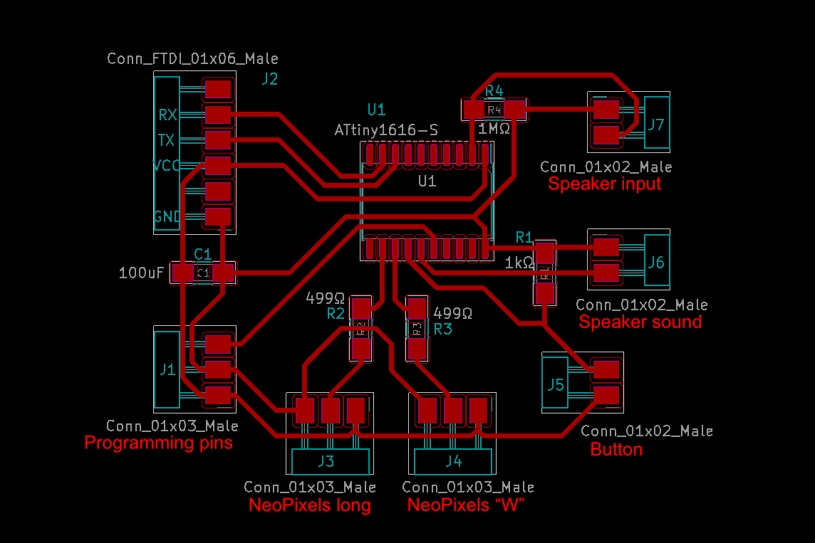
We started by creating a board for our LEDs and speakers in KiCad. Here's the diagram and schematic. We initially made them without one of the pin headers we needed, so we redid it and the finished product is above.
We milled the board we designed in KiCad and soldered all of the components onto it.
Once that was done, we tried testing a lot of the random speakers laying around our lab to see if they worked, and none of them did. We ended up using piezo speakers.
We were able to program one piezo to play a song when the other is shook!
Then we worked on getting the neopixels to light up. We had a UPDI initialization error, which was an issue with bad solder and path connections, which we fixed with a combination of scraping the copper and resoldering elements.
After fixing that problem, we tried using an external power supply for the neopixels by plugging that into a usb cable and then plugging that into a wall outlet. We think this fried the pin on the attiny which caused us to have UPDI errors again.
After trying a bunch of things, we replaced the attiny and everything worked out. We then combined the neopixel code with the speaker song code.
We needed to get the water from jugs in a freezer to a faucet.
We had brainstormed a lot of different ways of doing this but
once we started getting the parts a lot of the ideas started
to not really work. We ended up realizing that we needed to
use gravity to get the liquids to the pumps because they didn't
work under vacuum, and wouldn’t pump air. We then thought of a
cool way to clear the pipes after dispensing the drink. We then
got the fridge and decided that it wasn’t safe to drill a hole in
the side of the fridge, due to us not being able to locate the pipes
in the walls. So we had to fit all the plumping into the fridge.
The first thing that we needed to get done was to take inventory of supplies
we were going to need in order to get the task of plumbing done. Through
discussions with the other groups, our assignment through these two weeks was
to create a plumbing system that would offer four different kinds of beverages to the user.
Supplies:
Pump (DC 12V, Flow: 7.5LPM)
Pipes (OD = ¼in ID = 3/8in)
Valves
4 Tanks
4 Bulkhead unions
3 1/4in splitters
4 Adapter 1/4 in ID x 3/8 in MIP
3 Tee 3/8 in ID
5 Solenoids
4 N-Channel Mosfets
Orange and Brown Wires
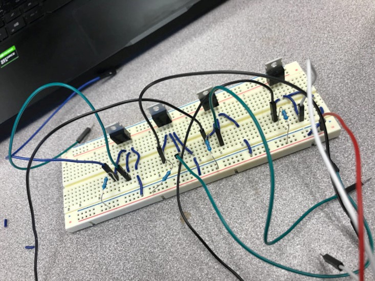
The first thing we needed to do was to test the pumps that came in with our Mosfets.
Below you can see the setup we used worked out onto a breadboard.
We needed this setup in order to convert 5V to 12V. The board consists of 4 transistors
each accompanied by a 5k ohm resistor. Below you can see a video of us finally getting the pump to work.
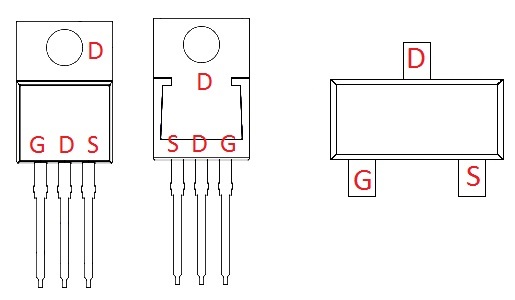
The Mosfets have terminals labeled gate, drain, and source. A Mosfet is similar to variable resistors but
where the gate-source voltage difference controls the drain-source resistance. We used a resistor to drain
the gate so that you can easily turn the Mosfet on and off.
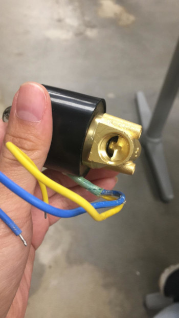
The images below are of the solenoid valves that we used. We then got them functioning using the mosfets.
The solenoid valves work by converting the current that is supplied into an electromagnetic field which
applies mechanical energy to move the valve to a desired position. This allows us to regulate the flow of our beverages.
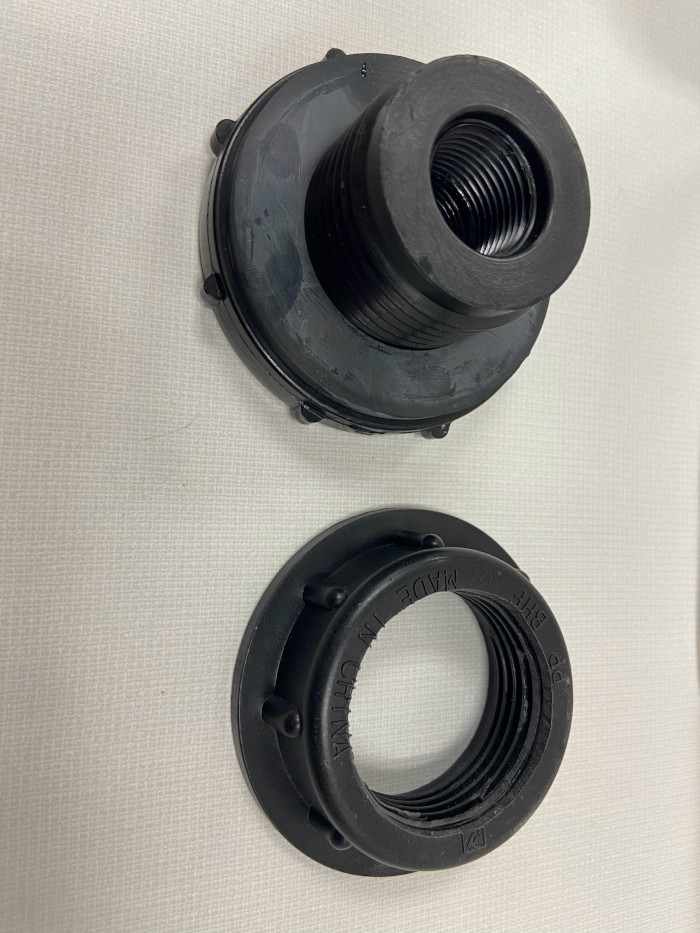
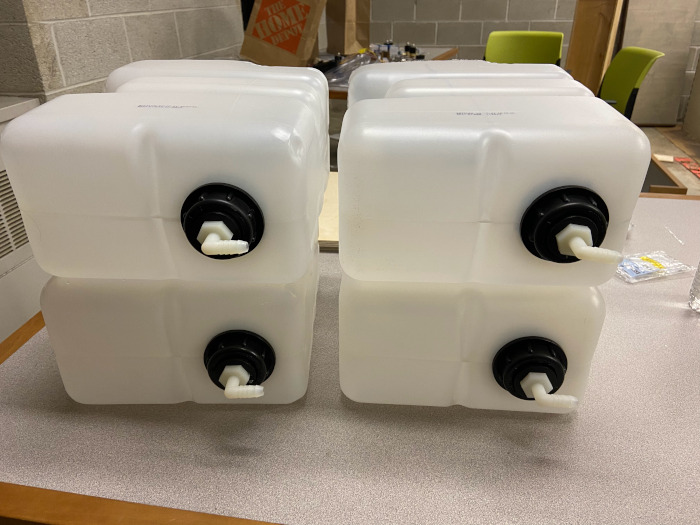
We originally had some larger jugs that we were going to store our beverages but we had to make some changes due to some
sizing issues. Below you can see the jugs that we used, we installed some bulkhead unions using teflon tape to secure a
good connection so as to not cause leaks.
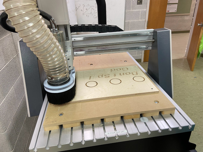
We made a stand for the jugs in the fridge so that we could fit our plumbing underneath it. It also had the extra benefit of
making the pumps closer to the jugs. We used the 3 axis mill to make the bed of the support
We made a stand for the jugs in the fridge so that we could fit our plumbing underneath it. It also had the extra benefit of
making the pumps closer to the jugs. We used the 3 axis mill to make the bed of the support. Below you can see the CAD model we made
in Fusion 360. We set this up in the manufacturing tab in order to mill it out the the 3 axis CNC.
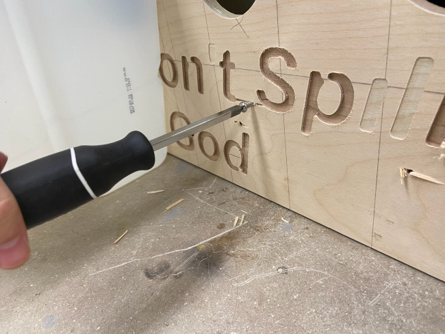
Below you can see the process of the board being milled out on our machine. We ran into some problems as fusion
really didn't like milling out the letters we had set to be cut out. But over all this stand was not going to be seen
by the people using the machine so we just needed the holes to works as intended.
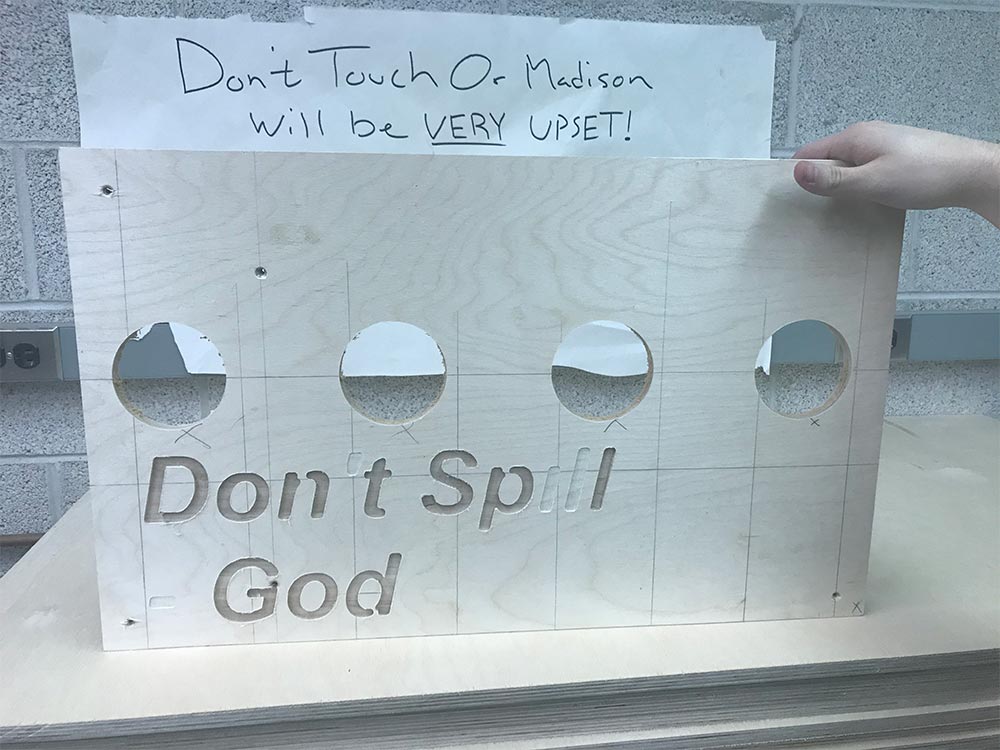
Below you can see the end procces after the Axiom finished its operation.
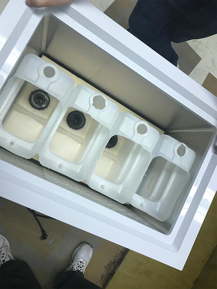
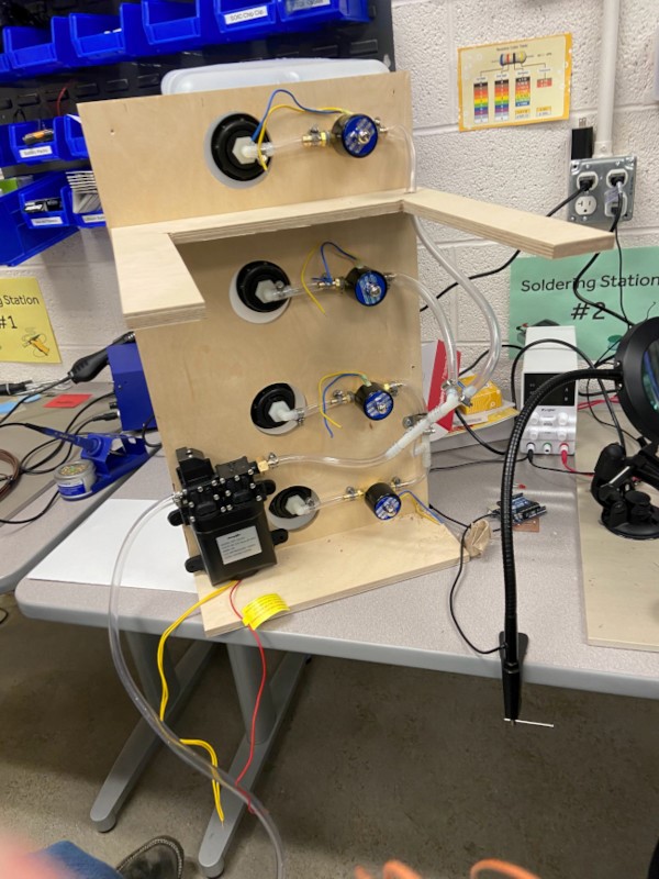
Using the stand we created with the 3 axis mill, our jugs fit perfectly into the fridge with room below for the solenoids
and pumps (the pumps and solenoids can withstand the temperature we are subjecting them to). This is a picture of the fridge
with the jugs on the supports
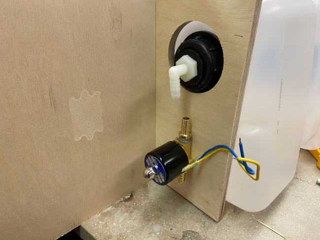
We attached the solenoids to the bottom of our stand as they had slots for screws of the top for exactly this reason. The jugs then
slot into their stand then with tubing connected with the solenoid with fittings and fasteners in order to not have any leaks.
After predrilling hole we secured the solenoids by screwing them on through the front of the board.
We slowly worked away at connecting pipes and valves until we got everything attached below is the end result, we have connected our four
solenoids connected to our flour jugs. We attached the valves to the bottom of the support board and then connected the valves with T joints which are then sent to a pipe that will eventually reach the faucet.
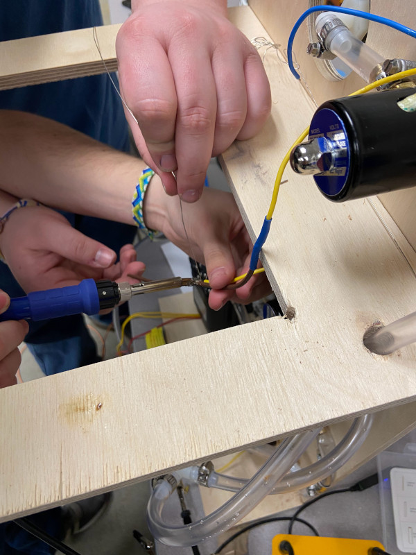
We had mutliple wires that needed to be spliced together as the pump had wires that needed to go to ground and powers, as well
as the solenoids. This single picture doesn't show the extent of the amount of wires we connected.
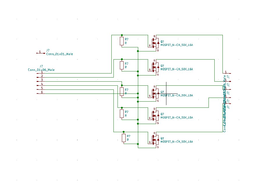
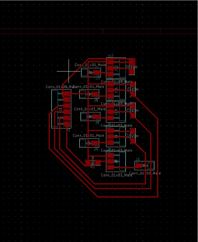
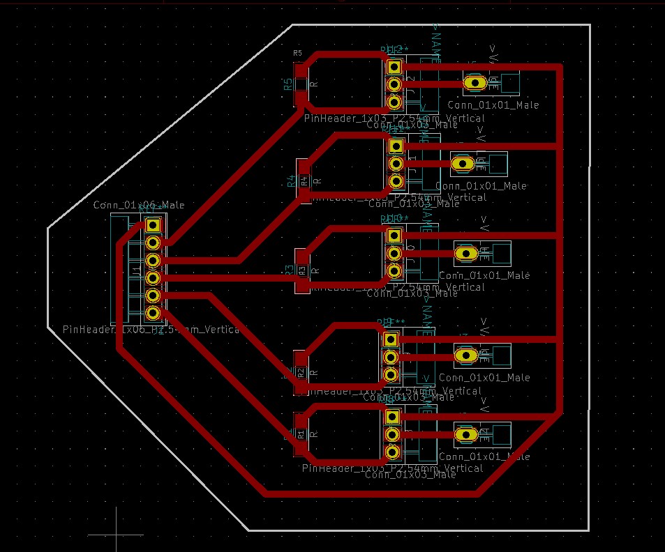
Next we needed to make a board that will be used with our mosfets that will be integrated with the electronics group. you can see our
initial schematic and pathing we made below, but we ended up getting confused with the drain, source, and gate of the transistors
and ended up routing the board incorectly. In this case we mixed up our gate and drain.
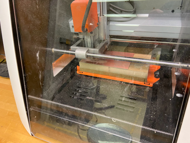
We milled out the board that ended up not working with the roland
Below is a video of how we have to zero our z axis. In a perfect world, since our board is no 100% flat,
we could use a tool that would map a gradient of our copper so that our paths would cut out properly.
Instead we had massive problem cutting our traces as our surface was in no way even. We cut our traces multiple times
all the while adjucting the zero of the z axis. When we first set it up, we tried zeroing our z in the middle of our cut,
but we had to set it more to the right in succesive cuts (we had to do traces multiple times).
Below is the full cutout of the board that didn't end up working.
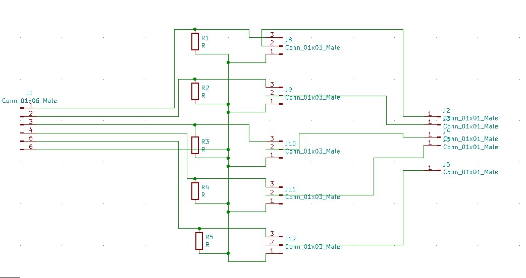
Below is the new schematics and pathing done where we have drain, gate, and source correctly pathed
this time around. Another added thing is the lines that were connecting to our power source were made thicker. We needed to
make the lines bigger not because of the voltage but because of power.
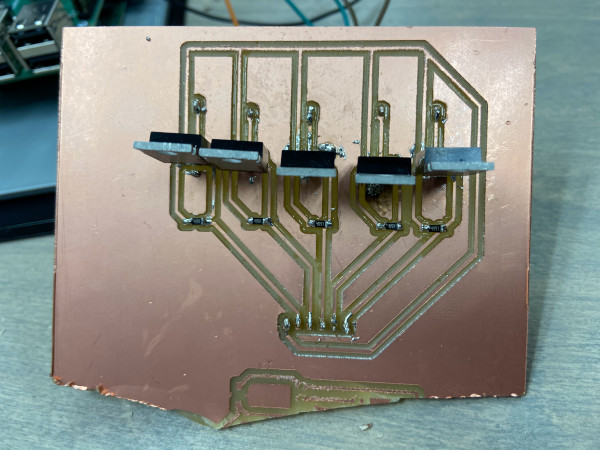
Below is our board fully milled out, as you can see we were in a rush and part of the board we were using had a
failed cut on it so we used a hacksaw to get our board instead of waiting over thirty minutes for our outline cut
to be done.
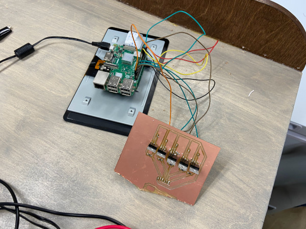
We collaborated with the electronics group in order to get out trasistor set up with the electronics they need in order
for it to control 12V with a 5V logic system.
We got everything set up in the feezer and everything was working as planned.
And that's as far as we have gotten so far. After a full night of troubleshooting plumbing issues, we were unable to get the machine to function as intended.