
This week we’re learning about molding and casting. Using a small block of machineable wax we need to use the CNC mill to create a 3-way mold; within the outline that is milled into the wax we’ll pour a molding material, which, after having cured, can then be used to create the actual pieces.
Assignments
Our tasks for this week are:
- Group assignment: review the safety data sheets for each of your molding and casting materials, then make and compare test casts with each of them
- Individual assignment:
- Design a mold around the stock and tooling that you’ll be using
- Mill it (rough cut + (at least) three-axis finish cut) and use it to cast parts
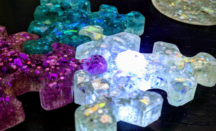
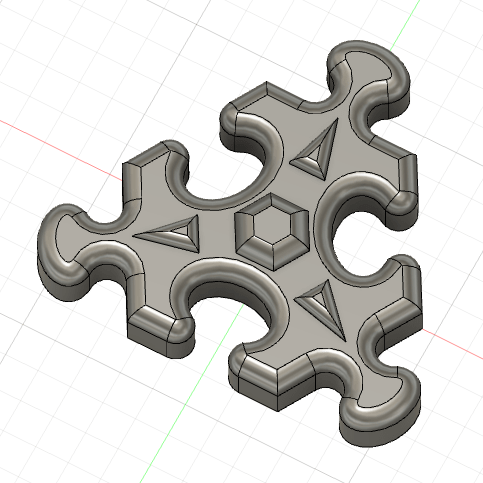
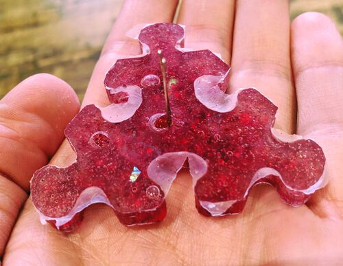
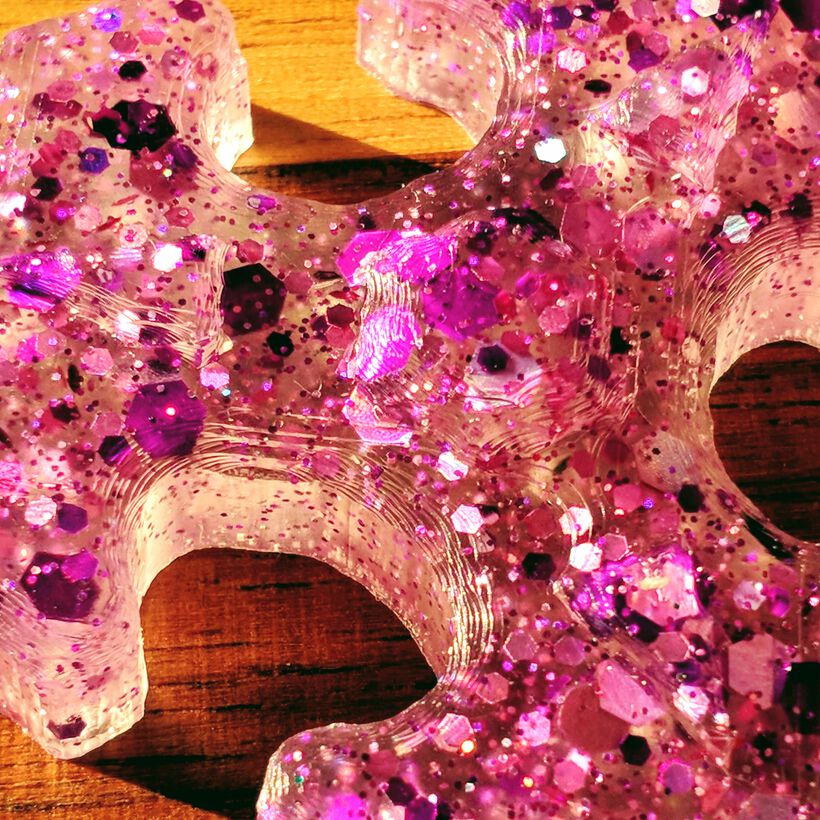
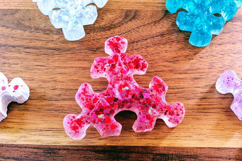
Hero Shots
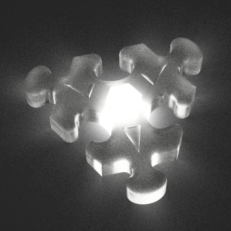
Showing some final results of the casted, glitter-filled, puzzle pieces for the tl;dr and hopefully showing you why the rest of this very long blog could be interesting to read (⌐■_■)


Testing Molding & Casting Materials
During the instruction day at the lab we got a quick intro in using VCarve Pro to set-up the 3D toolpaths and how to fix the wax block to the ShopBot’s table (which I’ll get to later), but in terms of casting and mold making we were pretty much just left on our own to try and figure it out. Henk had pulled out all the materials and a bunch of molds for us to play with.
Safety & Handling Summary
In general there are a few things to keep in mind when working with molding and casting materials.
In terms of safety:
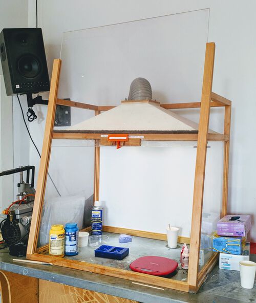
- Always work with these materials in well ventilated areas. At the Waag there is a small “chamber” with a fume extractor to do this.
- Wear vinyl gloves (I think nitrile is fine too, but latex is not), safety glasses and long sleeves
- If the casting material is even more nasty, wear a respirator

In terms of handling the material:
- Each material used for creating molds or final casts is based on creating a chemical reaction between two compounds that get mixed. When in separate containers, these compounds won’t get into any reaction on their own (although they don’t have an endless shelf life), but when mixed they’ll transform.
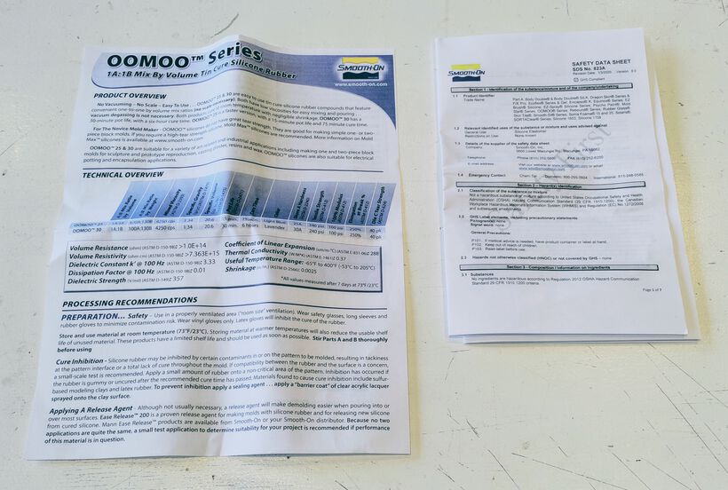
- Each material has a data sheet which gives instructions on how to use it, general safety measures to take, mixing ratio’s, curing times, etc.
- Each material also has a safety sheet that more elaborately describes the hazards of using it.
- For each material there is a mixing ratio to use for the two substances. This is often given in both volume (e.g.
1A:1B) or weight (e.g.100A:130B). We generally used the weight ratio and made sure to use a digital scale to measure it very precisely.- To figure out how much of the material you’ll need, you can fill the mold with water and either see what volume or the weight of the water.
- Each material has a pot life, which is the time you’ll have between mixing the two components and when the material’s viscosity doubles (apparently). It’s used as a proxy for understanding how much time you’ll have to mix and pour the material into your mold before it’s already started setting. These can be as short as 2 minutes to 30 minutes and longer.
- Each material has a curing time, which is the time needed for the material to fully set (most materials also have some post-curing time in a heated environment to get even better results). This can range widely as well from only 20 minutes to 16 hours.
- Depending on the material of the mold and the cast, you might need to use a release agent that will form a barrier between the mold and the casting material that you’re pouring into it. Some materials will otherwise stick together (e.g. urethane on urethane).
- For the best mold creation you want to have as few bubbles in the material as possible.
- While stirring always make motions that are on the horizontal plane (back and forth), and not moving up and down. Stir gently, not vigorously, but stir well, you want to have the two materials fully mixed and homogeneous.
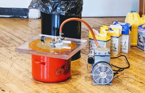
- Materials benefit from being placed in a vacuum chamber, so the air bubbles trapped inside will “boil out”. At the Waag there is a lovely, giant, cooking pot that has been turned into a vacuum chamber. After having mixed the two materials fully, you place it inside the pot, place the thick acrylic lid on top of it (making sure to place the silicon part over the pot’s edges), close the valve (on the left side), plug in the power, and wait for the pressure to drop inside. The liquid material will start to rise and release bubbles, like a mud pool. If you see that the material is going to rise over the container that it’s in, open the valve to let some air back in and try and find a balance between opening the valve and closing it again to not make the liquid gush over the container.
- Another technique to reduce bubbles in the final result is to pour the material into the mold very slowly, with a uniform flow, and from a single spot (at the lowest point) and let the material seek its level up and over the mold.
- It’s best to let any leftover mixed material stand in its container and let it fully cure before throwing it away.
Testing Materials
Nicole and I set out all the materials available at the Waag on a table and tried to order them in materials generally used for the creation of molds, and those that would be used for the creating of the final casts. From that we got the following list of materials:
Mold materials
- PMC 121/30 WET | Soft and Flexible
- OOMOO 30 | Tin-cure Silicone Rubber
- Mold Star 30 | Platinum Silicon Rubber
Casting materials
- Smooth-Cast 305 | Medium Setting - White
- Smooth-Cast 310 | Slow Setting - White
- Smooth-Cast 325 EU | ColorMatch - Pigmentable
- KX Flex 60 | Fast Cure 60A Urethane Rubber
- Clear Flex 30 | Water White Urethane Rubber (for professional use only)
- Crystal Clear 202 EU | Water Clear Urethane Casting Resin (for professional use only)
- Tarbender | Clear Epoxy Encapsulant
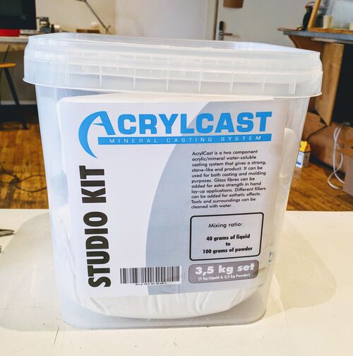
- AcrylCast
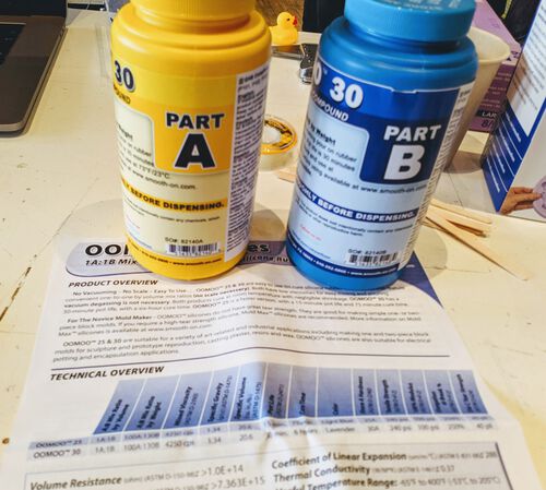
Nicole and I figured we’d start with a mold material first and randomly grabbed the OOMOO 30 to start with. We read both the data and safety sheet of the OOMOO:
Some points that stood out: It has a mixing ratio of 1A:1B in terms of volume, but 100A:130B in terms of weight. There is no vacuum degassing required to remove bubbles trapped inside. It has a royal pot life of 30 minutes and curing time of 6 hours. It should be used in a properly ventilated area. A releasing agent is usually not necessary.
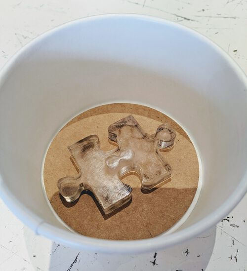
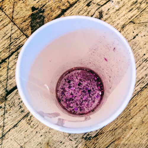
We grabbed a paper-with-plastic-lined cup. Loes had created some cardboard coaster that fitted in the bottom onto which we could tape whatever item we wanted to create a mold off. I’d coincidentally just created a test puzzle piece from acrylic for my final project, which seemed like a good candidate.
We measured how much water was needed to fully enclose the puzzle piece (and a bit above it, although in hindsight we should’ve added a bit more), which was 55g of water.

We set-up the materials in the fume extractor chamber and put on gloves and safety goggles. Initially I forgot to stir the separate parts and B before pouring them together, oops… (●__●)

On the second try I mixed the separate materials first, and only then weighed exactly how much we needed from each. What we did wrong then was that we’d used the water’s weight of 55g to figure out the weights needed for the OOMOO materials. However, they don’t have to be the same density (-> weight per volume) as water. Plus you can’t get all the material out of the container that you mix it in, so we should’ve used more. Nevertheless, we used 24g of part A (pink) and 31g of part B (blue-towards-purple) to get 55g of material in total. Trying to stop the flow of material from the yellow and blue bottles was definitely very messy, so keep some paper towels at hand to wipe the excess from the bottle’s rim before closing it (otherwise the next person might never get it to open again).
I mixed it for ±2 minutes until I couldn’t see any pink or blue colors anymore, just a soft lavender. Since vacuum degassing wasn’t needed, I poured it into the cup with the puzzle piece. What I did wrong then was that I moved around my (slow) flow instead of keeping it in one spot (and letting the material ooze around the puzzle piece itself).
Note | You might notice that I don’t have (m)any photos of the mixing and pouring process itself throughout this blog, because generally our hands were too dirty to handle phones during those moments.
With only 55g of OOMOO we noticed that it wasn’t getting nearly as high above the puzzle piece as the water had, and only then did we realize our mistake in using 55g of water as the exact value for the amount of OOMOO needed. Thankfully, a thin layer did cover the whole puzzle piece.
Nothing else to do there but clean up and wait (until the next day).
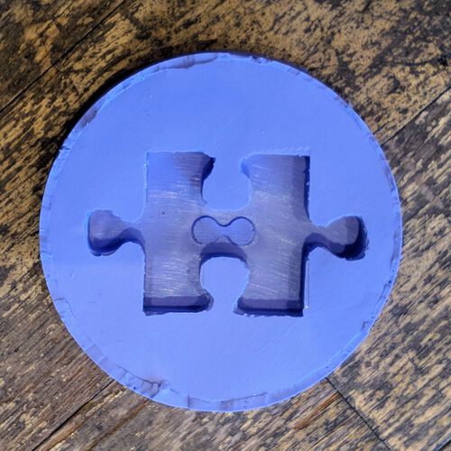
Jumping back and forth along time a little for the remainder of this section, the photos below show the resulting mold that came from this. When I pulled the mold from its paper cup the next day I saw that part of the mold had seeped below the cardboard that we’d used to tape the puzzle piece to. Removing the cardboard showed that the OOMOO had even flowed a little below the two puzzle piece’s “ears” that I hadn’t specifically taped to the cardboard.

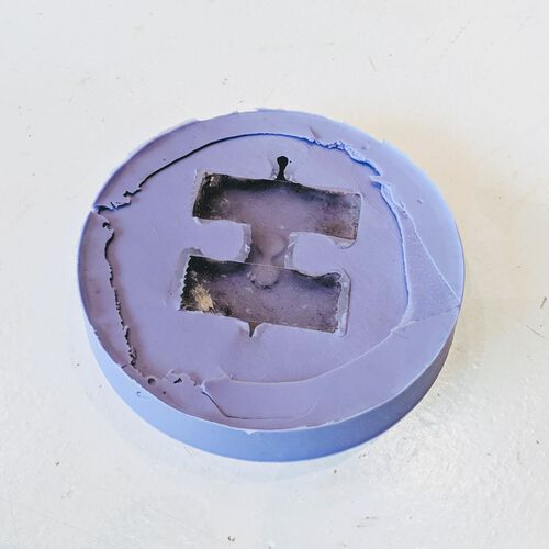
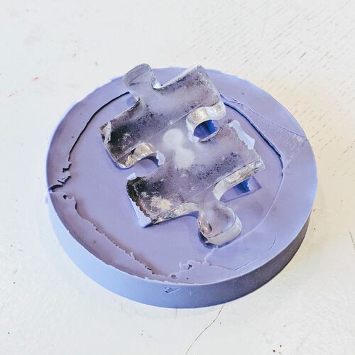
Using a knife I removed all the excess flaps of OOMOO that were not supposed to be there, which resulted in the following final mold.
Although I was interested in the Crystal Clear, I was taken aback by the big red “Not for personal use” warning on top. I definitely didn’t want to risk getting exposed to toxic fumes or develop an allergic reaction just to create some practice mold. Nicole and I therefore tried AcrylCast next, which seemed like a kind of plaster.
This time we took one of the available molds; a kitty head. We weighed its “water content” to be 14g.

This was the only non Smooth-On material. Its datasheet can be downloaded here. It actually seemed rather benign, it being non-toxic, water-based mineral/acrylic, there wasn’t even a safety sheet! You mix together 40 parts of the liquid and 100 parts of the powder. Its pot life is 6 to 12 minutes.
This time we took notice to have a laptop with the instructions for usage next to use when we were creating the mixture, to make sure we weren’t forgetting steps (like with the OOMOO):
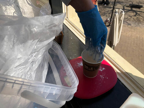
- First shake the liquid well and dispense into the mixing cup first.
- Then gradually sift the powder into the mixing cup until you have the appropriate amount.
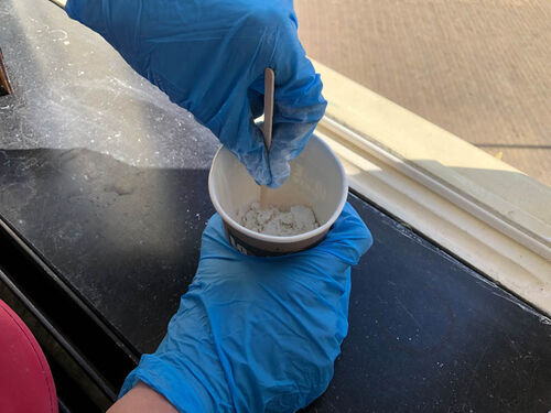
- This should soak for a minute.
- Next, mix thoroughly until the dry powder is evenly dispersed into the liquid (at least 1 minute of mixing) to a lump free, creamy consistency
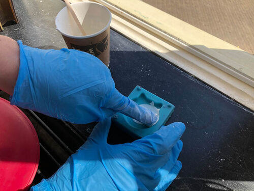
- For the pouring it is recommended to brush a face coat of the AcrylCast onto the surface of the mold (however we couldn’t find a brush, so I used my finger instead)
- Finally, pour the remaining mixture in slowly.
The datasheet doesn’t say what the curing time is strangely enough.
We used a lot more than 14g of total material this time and that was a good choice, because the plaster-like material didn’t want to come out of the mixing cup easily, but we had enough to fully fill the cat’s head.

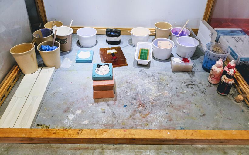
We then set it into the fume extractor chamber, next to all the other molds and casts that the other three groups had made.
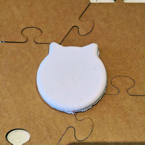
Phil had give us the advice to leave a little of the molding material in the cup, which you can use to test if the material is hard enough already. This showed me that the AcrylCast was setting really fast! I could pull the kitty head away from the mold after only an hour.
With almost all groups testing different materials, by the end of the group assignment day there was a mold or cast created from almost all possible types of options, except for the Crytal Flex, Crytal Clear and Tarbender, which nobody was in the mood for due to their more toxic qualities.
For example, Phil had filled a “knife” shaped mold with KX Flex 60, a white-ish flexible material with a pot life of only 2 minutes, so he had to work fast!
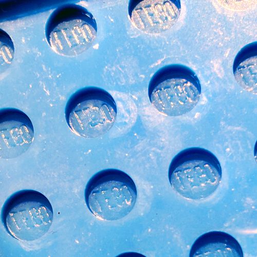
The group with Lucia and Loes was very enthusiastic, and applied all three molding materials to Lego bricks; OOMOO 30, PMC 121/30 WET, and Mold Star 30. These resulted in the following molds (taken out the next day):
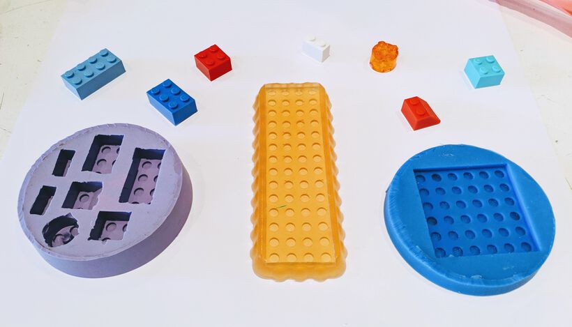
I was surprised to see the level of detail that was captured, even the tiny LEGO markings on each stud’s top was legible:
Lucia, Loes and Erwin teamed up to try the Smooth-Cast 325 EU, together with some red, white, and black pigments. Pouring these into molds of the Waag building, another cat head and a lamp. The pot life is only 2.5 minutes, so they had to work fast, and the cat’s head they did as their final mold, was done a bit too late, so it came out looking a bit…. scary

They also left a part of the lamp cast without any pigments, and I saw that this was a little transparent and would let through some light if an LED was placed behind it, which would be interesting to play with.
Design
I have to admit that I’m generally not one for “messy”, so this wasn’t quite the week for me. I therefore decided to go for something simple so I could be milling early on, and give other people more time to work on their designs instead.
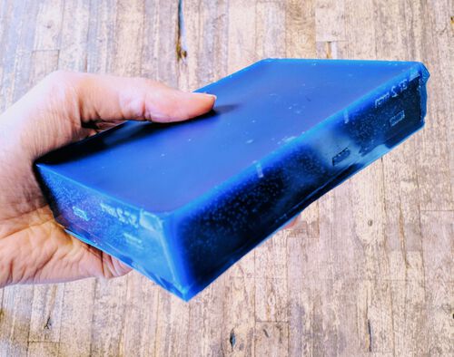
We all had a wax block with a size of 14.6cm x 9.7cm x 3.1cm.
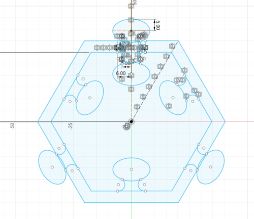
The idea was to create a design to cut out from the wax block, which, when fully poured, creates a mold for the final cast (see the brown squares in the image below). You then use those (brown) molds to pour the final casting material into, which will result in the final piece (a transparent ring in the image below); a three-way mold.
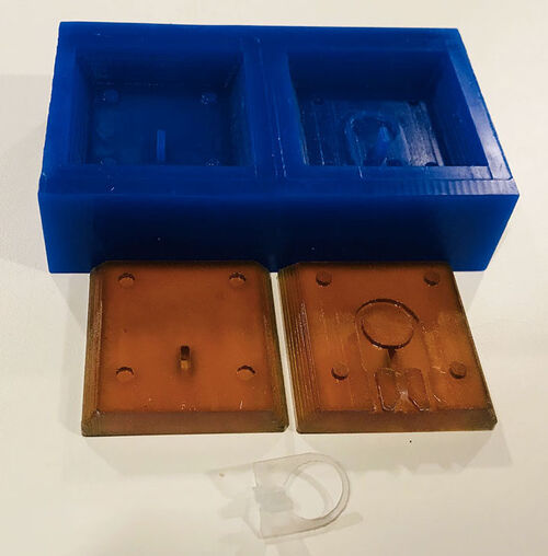
In terms of creating that wax version from the final design you want to create can be quite the mind bender, in thinking about creating the negative of a negative (thus you’re actually creating a positive for the wax).
Potential for Final Project
Initially I had seen molding and casting as a potential option for my final project; using it to create my puzzle pieces. However, the idea for casting is that you have one mold which is used to create many of the same pieces. Well, that idea is squarely against the concept of a puzzle, where you want pieces to be unique. Creating a separate mold for each piece would be too (material and) time-consuming.
I was considering something else though, where I would create one big rectangular block with casting material, so I could put “stuff” in there, such as glitters, or even the LEDs, to brighten up each puzzle piece. After that had hardened, I would then mill or laser cut out all the unique puzzle pieces.
However, I found that no hard-(almost)-transparent casting material is safe to mill or laser cut sadly; often releasing either toxic fumes when cut or glass dust when milled o(╥﹏╥)o
A Hexagonal Puzzle Piece
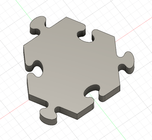
Even though I knew that this technique wouldn’t help my final project, I still wanted to create a puzzle piece. Just for this week I thought it would be fun to create a jigsaw piece of which I could create several, and then fit them all together. I also wanted to explore if I could stick an LED into the mold while making my final cast, so I could have the puzzle piece light up, and to put some glitters and other fun stuff into a (semi-)transparent casting material and see how that would look.
Naturally my puzzle piece would be based on a hexagon, not a rectangle (⌐■_■)
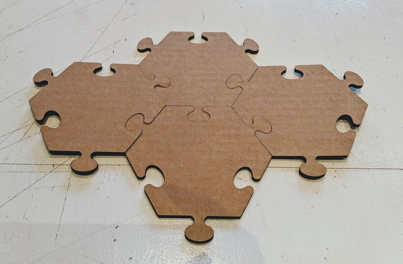
At the end of our instruction day at the lab, I quickly set-up a hexagonal puzzle piece in Fusion 360 so I could still do a laser cutting test and see if my concept for a “piece that fits in itself” was correct.
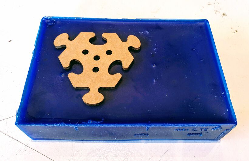
I hadn’t really checked the sizes while creating this piece, so when I saw what the laser cutter had made, I immediately knew that it was way too big to fit the wax mold we had. However, the pieces did fit together!
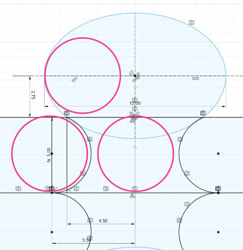
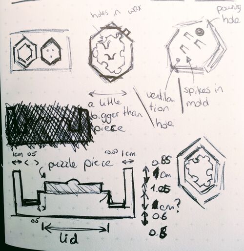
Back home during the evening I continued working on the design. I made the puzzle piece a lot smaller, however the “ears” with which a jigsaw piece is connected to another piece couldn’t become too small, since the milling bit we could use had a 5mm diameter. I therefore had to keep checking that the following curves were bigger than 5mm (the pink circles show a circle of 5mm diameter):
Having created a piece that was about 6.5cm on its longest side I felt that I had to add some ornamentation and rounded edges to create a more 3D design. Initially I wanted to created an undulating surface across the top, but I didn’t know how to make that, and I didn’t have the time to spend on (video) tutorials. I therefore tried a bunch of different things, all of which I wasn’t very pleased with
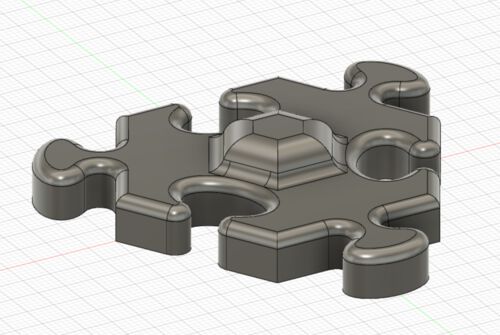

However, there just wasn’t a whole lot of space left on top of the puzzle piece for me to work with, combined with the fact that the milling bit was still quite large, so finer detail wasn’t possible either. I was therefore ok with only having some geometric smoothed bumps on the top.
Back in the lab the next morning I did another quick laser cutting test of the bottom side of the puzzle design. It did fit inside the wax mold. However, it was still too big, because I needed to take into account that both the wax block and the mold that would be poured into it would need walls of about 5 - 10mm thick.
I therefore had to make my design smaller still. I figured that I’d want the wax wall to be 10mm thick, the inner mold wall to be 5mm and the space between the puzzle piece and that wall to be another 5mm. I’d need those distances on both sides, so in total I would use (10 + 5 + 5) * 2 = 40mm for walls and such. That would leave me with 57mm for the actual puzzle piece, which I took into account when making the design smaller in Fusion 360.
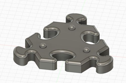
At this point the puzzle “ears” became so big in comparison to the piece that the overall shape was more triangle than hexagon σ_σ
Note | If you want to make a hole, be sure to make it a little bigger than 5mm. A hole of exactly 5mm diameter will be ignored in VCarve pro.
Just to be sure, I created a laser-cut cardboard version of this piece’s bottom side as well, and it finally seemed small enough when I placed it on the wax block.

Designing the Molds
Next came the “mind-bending” process of having to turn this model of the puzzle piece into a model that the CNC mill should carve out of the wax block.
For reference, I looked up the documentation from previous students by searching for “Fusion 360 mold Fab Academy” and found a few interesting pages. I saw that about half of those used a two-way mold instead of a three-way mold.
I also saw that many poured their casting material into an open mold, so you end up with a flat side on the top (so not a fully enclosed mold). Theoretically I could also use that for my design, since the bottom of a puzzle piece is flat. However, I figured that for the sake of learning, I would also create a fully enclosed mold, even if the top part of my mold would basically only be a flat lid.
In the lab there was a simple mold that created a cube, a dice. I thought that this technique of an outer mold with a smaller top would work for my puzzle piece was well:

Keeping those two sides of the mold in mind, I drew some sketches of the puzzle piece, the mold and then how the wax block should look to help me visualize what I had to create in Fusion 360:
I’d heard that it was best to use the 3D model of the final piece (in Fusion) to create the mold shape, and then use that shape to create the wax shape, while using cut (or similar boolean operations) to go from one design to the next. However, since my puzzle piece had a flat bottom, and the lid was almost flat, I found it much easier to go straight from the puzzle piece itself to the wax shape, skipping the intermediate “mold” shape.
I first create the bottom side of the wax model, using the dimensions of the actual wax block to set out the size of the bottom:
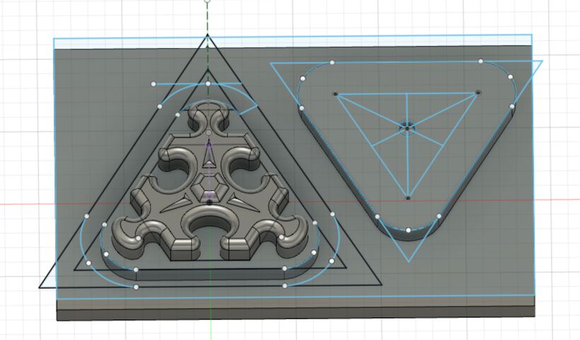
And when I had that, I simply extruded the walls of the bottom upward to finalize the wax model:
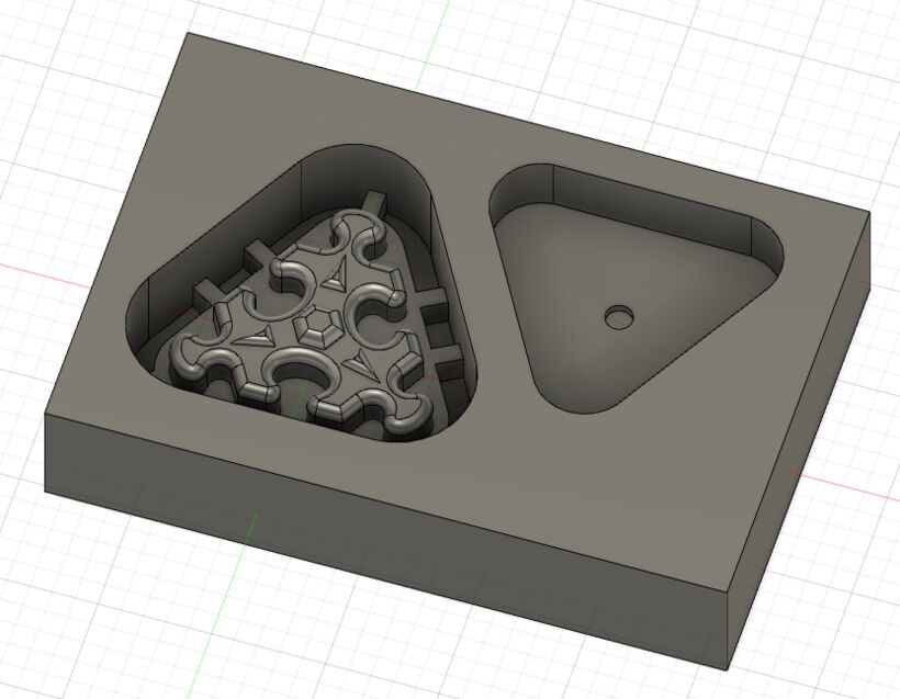
On suggestion from fellow student Phil, I added some “vents” around the outer walls of the mold. With such a flat and shallow design, he said it was better to fill the puzzle side with the casting material and then place the lid on top, letting the excess material flow out through the vents, instead of pouring the casting material in from the top.
I saved the model as an .stl file to import into VCarve Pro and turn into toolpaths.
Setting Up the Toolpaths
In VCarve Pro, set-up the dimensions of the material. Here I made it 2mm smaller than the actual size of my block on the x and y direction, thus: 95mm x 145mm x 31mm.
Note | I had understood Henk wrong during the explanation on the previous day and thought that I had to make sure that the “block” of my model was a little smaller than the dimensions of the block that I put into VCarve. However, it turned out to be the other way around; I had to make the block of my model a little bigger than the dimensions that I gave the block in VCarve, otherwise it would mill away the outsides of the block as well.
Next, go to File -> Import -> Import Component / 3D Model … and select the .stl file.
This will load the Orientate 3D Model window in which you can orient the model (the blue block) inside the material dimensions (the red wireframe outline of a rectangle).
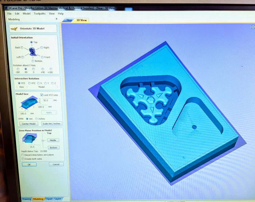
I initially had my model orientated 90° from the way I had aligned the material, but you can quickly fix this by setting Rotation about Z Axis to either -90 or +90.
In the Model Size click Center Model and in the Zero Planet Position in Model, move the slider so the red wireframe box is just a little above the blue box. Also, be sure to uncheck Discard data below zero plane, otherwise you’ll loose the bottom half in the next steps. I’m still not sure why the zero plane should be the middle of the block…
Although I’m not completely sure, but once you press OK on this screen there’s no way to return to it apart from starting a new file.
In the next screen, click the Toolpaths tab along the top-right side of the window. It will first show the Material Setup. In this you can generally leave everything as is. I was initially confused by the Model Position in Material setting, where you could choose a Gap Above Model and Gap Below Model. It showed that my Model Thickness was 24mm, but I’d set my block to be 31mm high in Fusion 30. I also didn’t know how to interpret the Modeling Plane Z being -15.3mm.
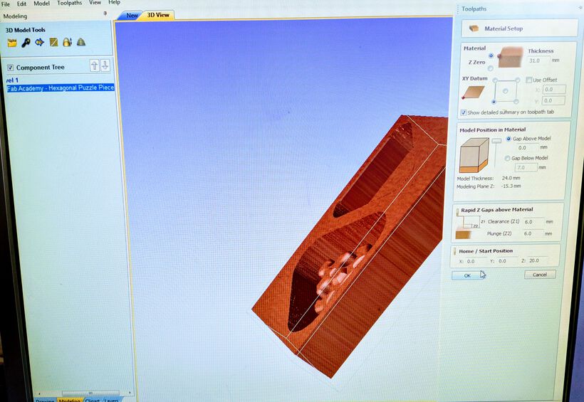
But I think I understand a bit now. You want to leave the Gap Above Model to 0mm. Although I’d made my Fusion 360 block 31 mm high, the lowest part that should be milled was 7mm from the bottom surface, so the functional part of my model was 24mm high. Furthermore, I think the Model Plane Z is the position at which the bottom of the full model is situated, assuming that the zero plane is in the center (I’m less sure about this). I’d set the block to be 31mm high, but positioned it just below the material, thus it could be that the -15.3mm comes from “(31mm - a little) / 2”.

After clicking OK in the Material Setup, you’ll see the toolpath options available. For this process we’re only interested in the 3D Roughing toolpath and the 3D Finishing toolpath options.
![]()
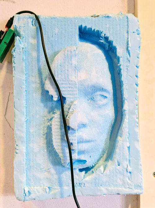
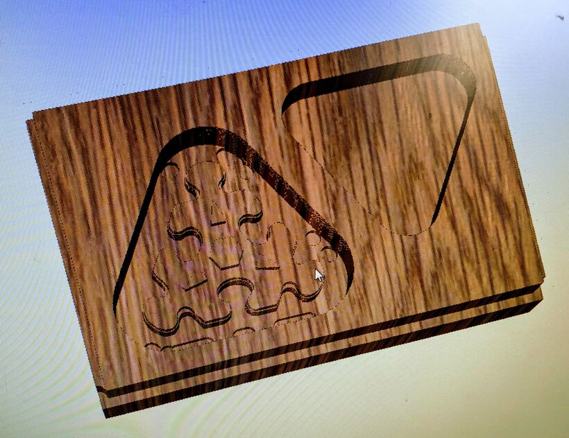
During the roughing toolpath you quickly want to mill away as much excess material that you can, so you can then use a much more precise and/or finer milling bits to do the fine finishing on the final surface. The image below shows an example where the left side is still in the roughing stage, and the right side has seen a finishing toolpath (and then the collet of the milling head bumped into the chin at the bottom sadly):
We’ll first create the 3D Roughing toolpath. Click on the icon and you’ll see the settings for this toolpath.
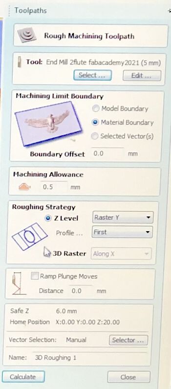
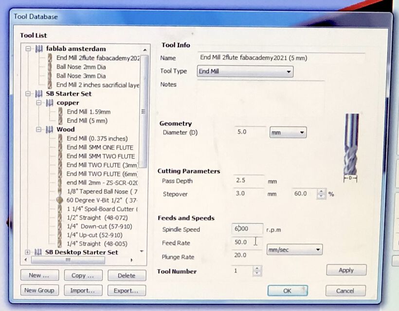
We would be using the 5mm flat end milling bit. Be sure to select the Tool, and pick the 5mm, 2-flute, flat end mill. For the roughing step:
- The Stepover is 3mm (or 60%)
- The Spindle Speed is 6000 r.p.m
- The Feed Rate is 50 mm/sec -> In retrospect I think that feed rate is way too high and one of the reasons why my mold looked so crude in the end, I’d therefore suggest trying 20mm/sec.
- The Plunge Rate is 20 mm/sec
Once done, click OK to go back to the general toolpath settings.
Set the Machining Limit Boundary to Material Boundary. Although I actually wonder if choosing Model Boundary isn’t the better choice. In that case I would expect that you shouldn’t have to make your model a little bigger than the dimensions of the wax block to prevent the machine from milling parts away from the outside. I’m only thinking this now during the documentation and didn’t test this during the milling, but if I mill a 3D model again, this could be interesting to test.
The Machining Allowance is “a virtual thickness which is added to the 3D model when the Roughing Toolpath is calculated. This ensures that the toolpath leaves some extra material on the roughed part”. We assumed that the default setting of 0.5mm would be good.
For the Roughing Strategy I choose the Z Level - Raster X option, so the machine would move back and forth along the long edge of the wax block, thereby having to make fewer stops and turnaround versus the Raster Y option. (I do wonder what the Profile … First is, or the 3D Raster, I never took the time to select these and see how the resulting toolpaths looked).
I kept the Ramp Plunge Moves unchecked and finally pressed Calculate. Back in the toolpath options, it’s best to click on the icon to see an animation of the resulting toolpath (in case the animation window doesn’t come up automatically). When I watched the animation I felt that the final result of the material remaining after the roughing job was done looked a little odd in some places (e.g. see the two circles along the right side of the left pocket in the image below), however that was fixed with the finishing toolpath that came next.
Click on the 3D Finishing toolpath icon. Be sure to configure the Tool again. For us, we’d use the same 5mm 2-flute flat end mill, with all the settings the same as the roughing toolpath except for the Stepover, this should become 0.5mm (or 10%).

For the Area Machine Strategy … I went with Offset, where it basically goes around in a rectangular spiral. I don’t think there’s much different with Raster in how the final result will look.
With the finishing toolpath done was well, I watched the animation again and saw the the final result this time looked as the final model should.
Those were all the steps needed in VCarve pro. Save both the roughing and finishing toolpaths into one .sbp file, which can be used by the ShopBot CNC mill.
Creation of the Wax Mold
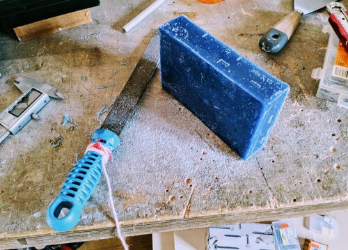
All the wax blocks we could use this week were created from leftover wax material that had been melted and turned into new blocks. This left some inconsistencies, such as the bottom and top side not being perfectly level, and some edges having excess wax.
Before I placed my wax block on the CNC machine’s bed, I sanded away those excess edges.
A good way to fix the wax block to the bed of the CNC machine is to place four wooden planks around it, applying pressure to the sides while screwing the wooden planks to the machine bed.
I always find that I’m not that smart when it comes to practical things (theory is more my thing I guess), so I wasn’t that surprised that I had screwed three planks into place (with Phil helping me push the planks down), and only then realizing that there was no room for the final wooden plank (*≧▽≦)
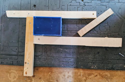
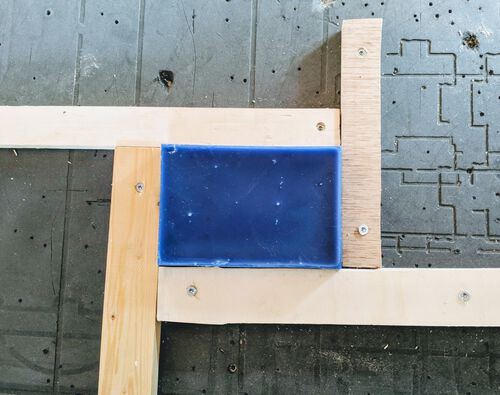
While screwing the third and fourth plank, it helps to push the far side of the plank in the direction towards the wax, this will create a pressure on the wax block, making it really well fixed in place.
I turned on the ShopBot and followed the steps as I have outlined in the summary of the “Computer-Controlled Machining” week to set-up thee machine; homing it to its absolute zero, setting a x and y origin point above the wax block, z-aligning on the wax block, etc.
Setting the x and y origin wasn’t that easy to align perfectly I found (and expected). This was a reason why I wanted to make sure the outer walls of my 3D model were a little thicker, so there was some room for error.
For the Z-aligning you want to pick the lowest point on the wax block. However, because the metal rod to do the z-aligning with it so big, it’s basically impossible to z-align it there, because the metal rod will be placed over a larger area of the wax block. I tried my best, but I think the machine was still aligned a smidge too high.
Note | Something that I forgot to check, but was thankfully correctly set for my design was the length from the tip of the milling bit to the collet. This needs to be larger than the maximum distance that you’re milling, otherwise the collet will bump into the wax and destroy it. Thus make sure to check that the distance from the tip of the milling bit to the collet is larger than the maximum depth that you’ll mill.
With all of the aligning done, I was ready to start the job. I turned the key to start the spindle. Thankfully, Douwe, Phil and Michelle were there (to watch), and all told me to adjust the speed of the spindle. I was confused at first, I’d set thee spindle speed in VCarve Pro. Sure, I could hear that the spindle was moving fast now, but I expected that once I loaded/started the toolpaths, that the spindle would thus slow down to 6000 rpm (just as it also takes the plunge rate into account).
Well, that was wrong. You need to manually adjust the spindle speed on the ShopBot. I had no idea! This must’ve completely passed by me during the computer-controller machining week ✖_✖
Thankfully it’s very easy to do. There is a small box below the bed of the ShopBot. Press the little buttons to either increase or decrease the speed:
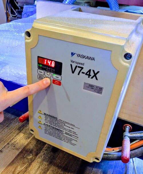
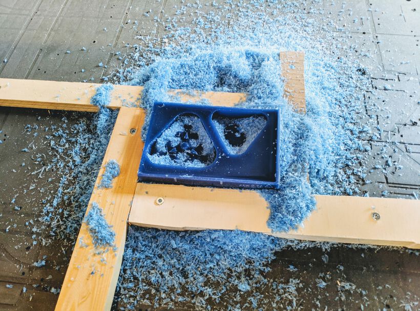
With the spindle slowed down to 6000 rpm it was time to start the job! Another big change w.r.t. to milling wood is that for milling wax you don’t turn on the vacuum. That’s because you want to save the wax scraps, to be melted down again later to create new blocks.
To summarize how the steps for the milling a wax block are different from milling wood:
- Tool settings in VCarve Pro:
- The spindle speed is 6000 r.p.m, the feed rate is 50 mm/sec (too fast? try 20 mm/sec), the plunge rate is 20 mm/sec
- The stepover percentage is ±60% for roughing and ±10% for finishing (but I think you can decrease that final percentage even farther if you want a really smooth result)
- Fix the wax block to the machine bed with four wooden planks, applying pressure on the outsides of the planks when screwing them into place
- Z-align on the lowest part of the wax block
- Check that the milling bit sticks out farther than the lowest distance you want to mill
- Be sure to set the spindle speed on the ShopBot itself with the box below the machine bed
- Don’t turn on the vacuum, you want to re-use the wax shavings
The milling went pretty fast, but then again, the wax block was really quite small to begin with.
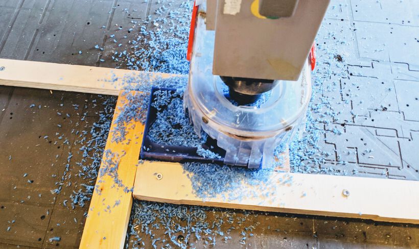
It was quite clear to see when the machine went from the roughing to the finishing toolpath; for the roughing it followed the outer lines of the actual design, the shapes, whereas for the finishing it really went like a rectangular spiral from the center outward, moving up and own along the way:
I forgot to time it, but I think it was done in about 30 minutes. I unscrewed two of the wooden planks (the fellow students could reuse the other two), and scooped up all the wax “dust” into a plastic bag.
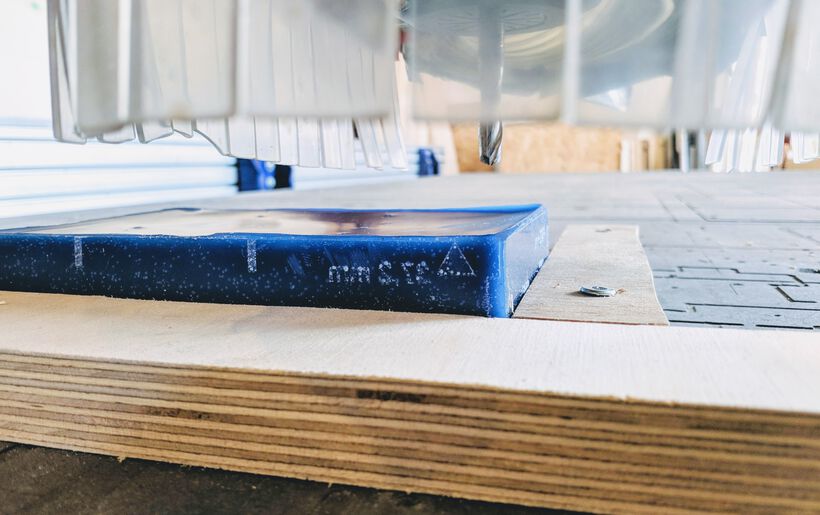
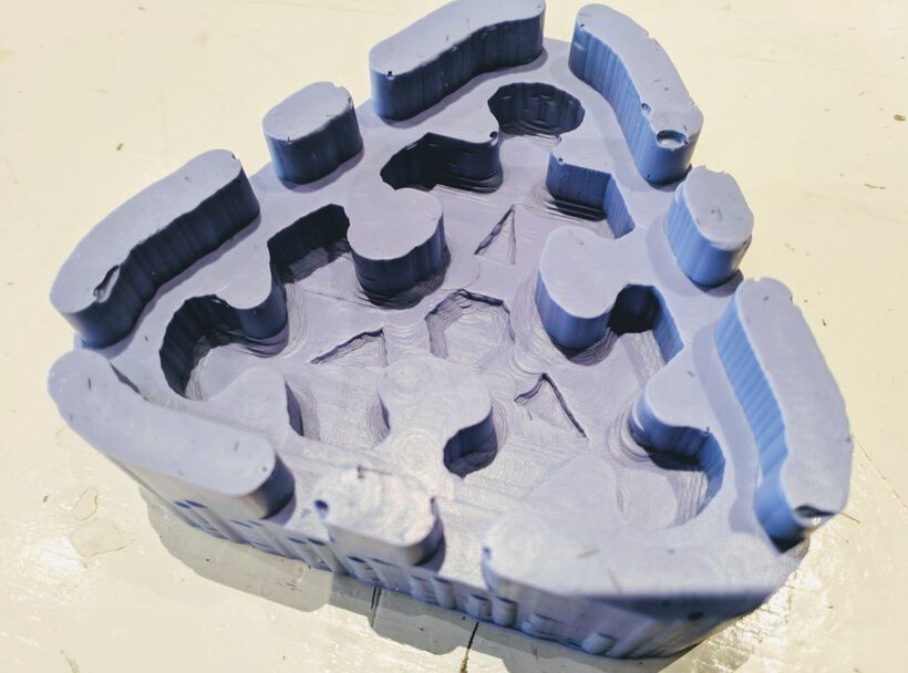
After trying to clean out all the wax dust with a paper towel and some water, this is how the block looked
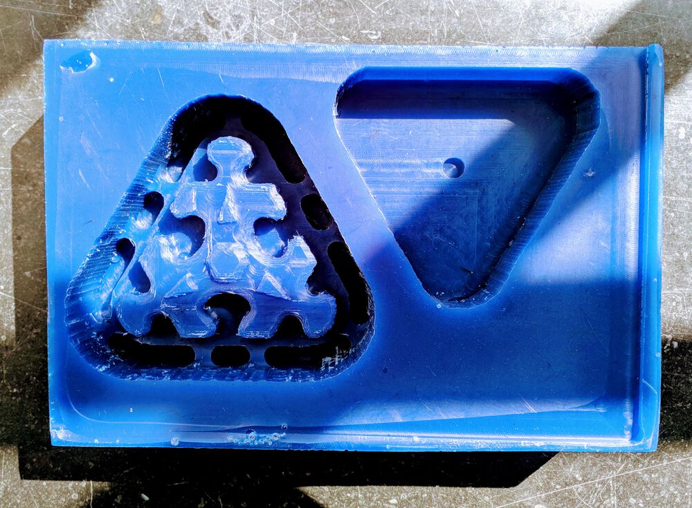
But I have to admit that I was expecting the finishing to be more smooth. The rounded corners on the top triangles and hexagon were definitely not as round as I had in my design, and the rounded corners of the puzzle piece itself were a bit crude all around. So I was a bit disappointed (╥_╥)
I wonder how the results would’ve looked with a smaller or a ball head milling bit in all honesty, because this doesn’t look any better than what a 3D printer could do in terms of lines and detail from what I can see.
Creation of the Silicon Mold
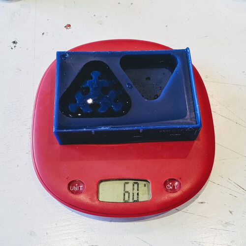
I filled both of the pockets in my wax block with water to see the weight that fitted in there. For the left pocket that was 60g and for the right pocket it was 40g.
I knew that I wanted my final cast to be from a hard material. Therefore, it would be good to use a flexible material to create a mold from the wax block. From the three flexible mold materials in the lab, PCM 121/30 Wet, Mold Star 30 and OOMOO 30, I disregarded the PCM from the get-go because I didn’t need a mold that would last for a long time, and that stuff just looked and felt awful. I actually wanted to go for the Mold Star, because the Crystal Clear resin mentioned that one specifically as a possible material to cast in. However, the bottles felt so empty that I was afraid there wasn’t enough left to fill up my mold to the top.
Just to check I weighed both bottles of the Mold Star, which both were about 150g. It was hard for me to guess how heavy and empty bottle would way, but I guessed that it would be more than / around 100g, which would indeed mean that there wasn’t enough material left inside.
I therefore decided to go for OOMOO 30. Although the OOMOO wasn’t mentioned specifically in the data sheet of the Crystal Clear, it did say that a tin-cure silicone rubber would work. From the three flexile mold options it also felt the nicest, looked the nicest (with its lavender color) and was quite easy to handle, needing no vacuum degassing for example.
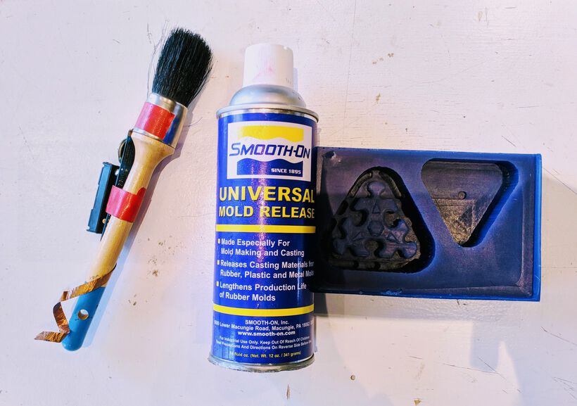
I first sprayed a layer of mold release agent into my mold and brushed it around with (the only) brush that Henk could find in the entire lab. While I was waiting for that to set I went over the data and safety sheet of the OOMOO again.
Gathered some cups, paper towels, wooden sticks (for stirring). I needed the equivalent of 100g of water in OOMOO. From trying the stuff the day before I knew that meant quite a bit more weight for OOMOO. I decided to go for 130g of OOMOO. OOMOO has a weight ratio of 100A:130B, which meant that I’d need 57g of substance A and 73g of substance B. I then began weighing and mixing the OOMOO together under the fume extractor. I think that I picked a paper cup that was too narrow, because it was hard to mix the two compounds together (the wooden sticks at the lab are also quite thin and bend easily if too much force is applied).
Because I hadn’t tried it before, I used the vacuum pot on the OOMOO (it has a pot life of 30 mins, so I figured I could take things slow), to at least get some experience with it, even though the data sheet said that it wasn’t needed. I did see some bubbles come out, but it wasn’t a whole lot.
I then very slowly started pouring in the OOMOO into the mold. I oriented the flow in one corner, which then seeped over the puzzle piece. However, at some point the level at that corner had almost reached the top of the mold while the full mold wasn’t full yet. I therefore very slowly moved to another corner of the mold and continued.

Once I finished the bigger of the two pockets, I was worried that there just wasn’t enough left for the second pocket. I started pouring in anyway, if it was really not enough I could try to quickly make more, since the pot life was quite long. But although I couldn’t quite reach the top of the second pocket with the remaining OOMOO, I felt it was far enough (only 2-3mm below the top).
Although I forgot about this, I could’ve tapped the mold gently to try and move up some remaining bubbles.
OOMOO has a curing life of 6 hours, and it was late on Friday afternoon. I therefore left the wax block inside the fume extractor, cleaned everything up, and went home.
Later, Henk mentioned that I could’ve sanded my wax mold to remove some of the crudeness. However, even if I’d seen his comment before I’d cast the OOMOO, I think I still wouldn’t have sanded the mod, because they’re puzzle pieces. Sand away stuff, and they won’t fit together nicely anymore (although I was pretty sure the crudeness of the milling would result in puzzle pieces that wouldn’t fit anyway (╥﹏╥) )
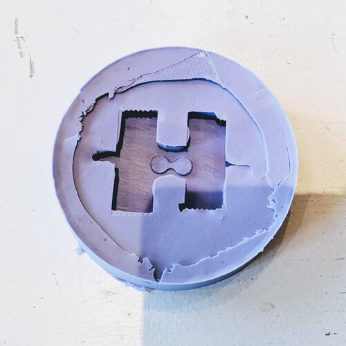
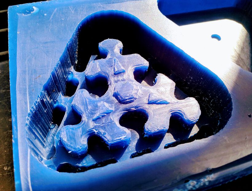
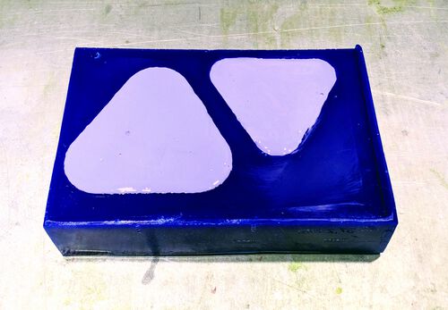
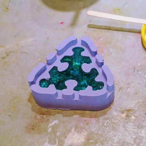
Back in the lab on Monday morning I slowly pulled the OOMOO silicone molds from the wax block, which took some patience. I knew that it would’ve been better if I’d made the walls slant inward towards the bottom. However, that meant giving the “wall” section even more thickness, which would have been taken away from the puzzle piece itself. Therefore, I had decided to go with straight walls.

The OOMOO had done its job really well, capturing the minute detail in from the wax block. In this particular case that was a bit unfortunate, because the carving from the wax block had been quite crude, so this was now also reflected in my mold. Nothing to be done about that sadly.
I was surprised to see how many bubbles were captured in my mold. They were thankfully all on the walls, except for two small bubbles along the “nek” of the top puzzle’s “ear”.
Creation of the Final Casts
I measured the weight of water that would fit into the mold, which was only 11 grams.
Having checked out all the casting materials in the lab, I decided to go with Smooth-Cast 325 because it’s a transparent material. Not as clear as water (or Clear-Cast), but clear enough from what I could see online. It also has a curing time of only 10 minutes, so I could quickly create multiple puzzle pieces. Such a fast curing time also means that it has a ridiculously short pot life; only 2.5 minutes, so no vacuum degassing possible.
After cleaning my molds, I sprayed them with the Release Agent, since the datasheet of Smooth-Cast mentioned that this was required of most surfaces. I found a proper brush this time to smear the release agent into all nooks and crannies.

During the previous week I had bought a whole bunch of (cheap) glitter to play with during the casting (they were meant for resin and nail art).

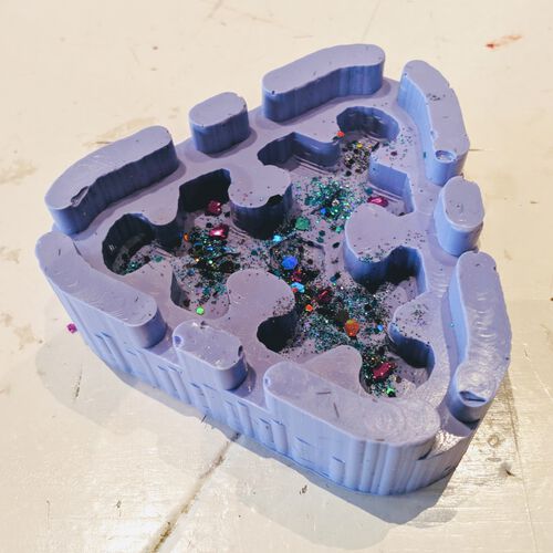
For my first try I sprinkled some glitter into the mold itself.
I grabbed a blue LED which I pushed through the top mold. I’d initially made a dent there to help me find the exact center. However, I now realized that I never measured how high an LED is versus how high my puzzle piece was (*^▽^*)ゞ With the LED on top of the dent, I could feel that it was bumping into the top of the other side of the mold when placed together. I therefore cut away the dent, which was just enough to make the LED fit.

Eleven grams of casting material was not much. I wasn’t yet sure how liquid the Smooth-Cast would be, and how much would stay behind in the mixing cup. I therefore decided to play it safe and weigh for 30 grams. With a weight ratio of 115A:100B that would mean 16 grams of A and 14 grams of B.
I then did something a bit silly. As with all materials that I’d read the datasheet of, this one also said to “Stir or shake both Part A & Part B thoroughly before dispensing”, and somehow I figured I’d shake since that works better than stirring generally. However, shaking introduces a lot of bubbles! After about 3 seconds of shaking both bottles I realized this, stopped immediately and checked the contents of the bottles; yup, bubbles everywhere, dammit!
With the ultra short pot-life, I wouldn’t have the time to get rid of the bubbles after mixing. I therefore placed the bottles themselves in the vacuum pot, more than half of their contents was already gone, so I wasn’t afraid that it would overflow. This really helped tremendously to get rid of most bubbles. I stirred both bottles a little afterwards to break up the final bubbles that were floating on the surface.
After adding the substances of A and B together and mixing, I noticed that it was very viscous, but also that the substance first turned milky-white and became opaque before switching to becoming completely transparent in only a few seconds.
I slowly poured the substance into my puzzle mold, sprinkled more glitter on top, and placed the top part of the mold onto it, letting the excess material squeeze out through the side “vents”. I also saw that 30 grams was way too much material, since it poured so easily.
After about 20 minutes I opened up the mold, and the puzzle piece came out very easily. There was a very thin layer of material around the piece, but it was easily removed with a knife of file.
Like with the silicone mold before, the Smooth-Cast had done an awesome job of forming to the mold, making the crudeness of the original wax block really apparent ಥ﹏ಥ
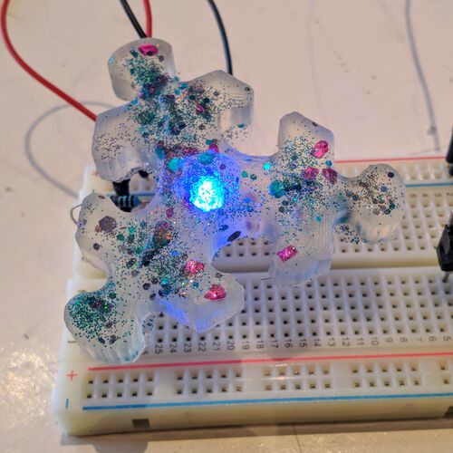
I’d prepared a simple breadboard in which I could place the LEDs legs and see it light up:
I wasn’t happy with the way the glitter had settled into this puzzle piece. I therefore set everything up again for another try (without an LED). And this time I added the glitter into the mixing cup. I went with 20 grams of Smooth Cast 325 (meaning 11 grams of A and 9 grams of B), which was still too much I found.
After I took out the puzzle piece, I noticed that it was still a bit squishy, it hadn’t completely hardened out as the previous puzzle piece had. With the glitter mixed throughout the material, it was apparently messing with the curing time.
This time the glitters were much better spread throughout the piece. The biggest glitters had indeed settled down more towards the bottom of the mold (which was the top of the puzzle piece), but there was definitely a presence of glitter throughout the piece.
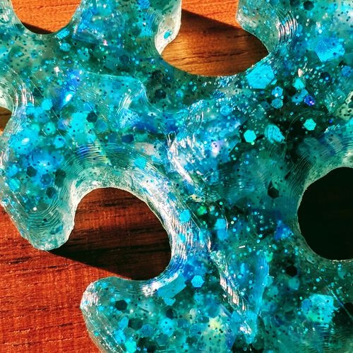
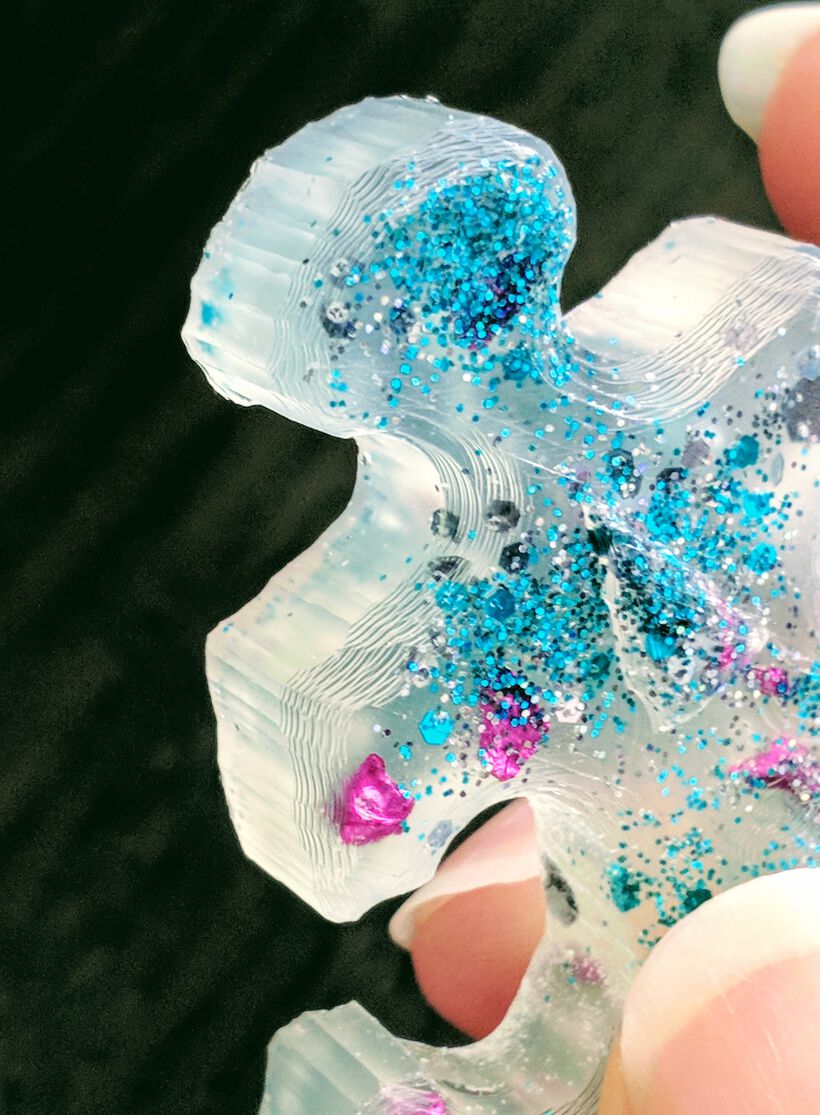
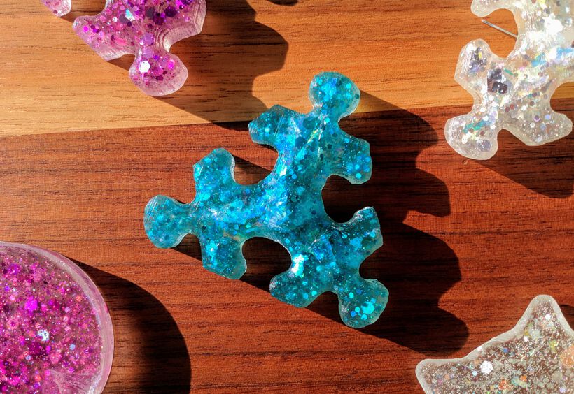
I set up again, choosing a blue glitter, and also adding in a bunch of chromatic blue flakes. I mixed 15 grams this time (8 grams of bottle A and 7 grams of B), which was about the right amount.
The chromatic flakes really made the puzzle piece look even more interesting than with just the glitters (which I’ve not been able to capture very well with my camera).
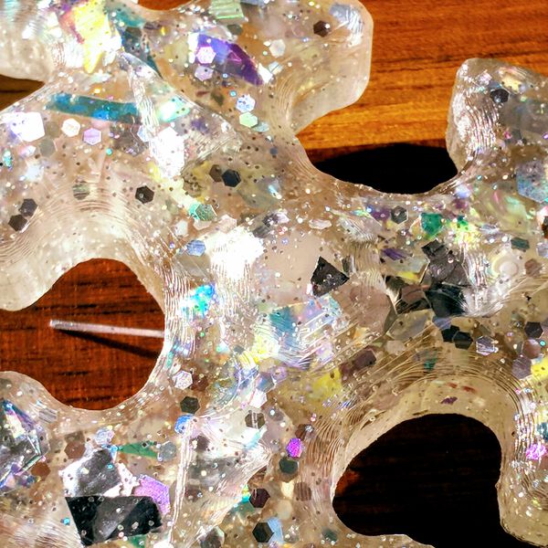
Having figured out a “glitter combination” that I really liked, I set everything up again to make another piece using silver chromatic glitters and flakes, but also adding a white LED in the center. The glitter inside looked really nice!

I’d poured the tiny bit of casting material that I had left over into the cat’s head mold. Interestingly, the top of this thin piece, which had nothing resting on top of it, became really clear (see the image above right), whereas that bottom that was touching the mold became a bit matte, like all of the puzzles pieces were too.

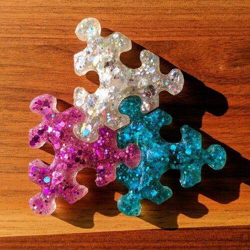
I naturally tried to fit the four puzzles pieces that I’d created into each other. While the puzzle piece was still a bit elastic/squishy I could push a little and make it fit. However, after they hardened out, it wasn’t possible anymore. Thankfully, I’d brought some tiny files with me and sanded the ears of each piece into a more rounded shape. And after applying some pressure, they could fit, sort of.
I also tried the AcrylCast with the glitter to see how a white non-transparent material would look.
During the group assignment this material had hardened in no time. However, this time it took 1-2 hours before the “test” cat head (with leftover material) was set enough. Sadly, when I tried to take the puzzle piece from the mold, one side broke off (>_<)


As expected, the result wasn’t nearly a beautiful as using a transparent material with glitter.
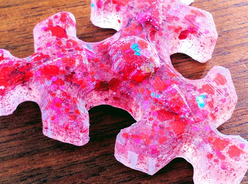
For the fun of it, I made one final puzzle piece from Smooth-Cast 325 with red glitter and a red LED placed on the center.

Reflections
The most messy week of all, involving many steps, from design to wax to silicone to final casts. But somehow it wasn’t very time consuming for me this week, I even took several hours in the weekend to bike/walk/sit outside and enjoy the sun (*≧▽≦)
What went wrong
I would say that the wax mold went “wrong”, it was way too crude. A 3D printer would’ve created a better looking mold than that.
I also did a bunch of things wrong during the group assignment, where I initially forgot to stir parts A and B before pouring them together, moving around while pouring it into the mold, these kinds of things. However, I guess that’s also what the group assignment is for, to make and learn from those mistakes before you work on your individual assignment.
What went well
My design for the wax mold was correct. I did have to remove a little nub on the bottom because I’d forgotten to measure how high LEDs generally are, but other than that both molds fitted together to make puzzle pieces. Then again, my mold design wasn’t very complex to start with.
I also created several puzzle pieces and after some experiments am quite happy with the “glitter” approach to use and I found that this really made the pieces look more interesting.
What I would do differently
I really would’ve liked it if the milling had done a better job, that it would’ve truly reflected the smoothness of the surface that the original design had, and that I’d seen in the examples during Neil’s lecture. I think the machine was perhaps set too fast? I could definitely feel lots of vibrations if I placed my hand on the CNC’s bed while it was working. With such a small design, these vibrations could have resulted in the crudeness? Perhaps the feed rate or plunge rate could’ve been set to 20 both (or lower still), perhaps I should’ve gone for the 3mm milling bit instead? Perhaps I needed a ball head for the finishing round?
The fact that I can’t answer those questions, because we only had 1 try on the CNC machine is something that I was sad about. I’m really a prototyper that wants to experiment and keep improving until the result has the level of detail/smoothness/perfectionism that I have in mind.
If the puzzle mold had looked nice and smooth, I might’ve given the more toxic Clear Cast a try. But with these pieces I just didn’t feel that it was worth the hazard.
Wrapping up
I’m guessing it’s clear from my words throughout this blog that this week felt somewhat disappointing to me. I was just so sad to see the crappy job that the milling machine had done with my design in the wax block. And then of course that crudeness being reflected in the molds and final casts as well.
I’m really glad I bought the glitter though, because that made it all a bit fun again. I do wonder how long glitter will be found around the fume extractor area (I tried to be careful though!) (^.~)
I actually like the glitters so much that I really wish there was a casting material that I could laser cut afterwards to use for my final project; creating a big block (but not high) of transparent material, filled with glitters, and using that to cut my puzzles pieces from. I asked the Global Open Time if they knew of any transparent casting material that could be cut/milled. But I couldn’t find the two (transparent) materials suggested, Delrin and High Density Polyethylene, as (home) casting materials sadly.
All Files Together
- The STL used for the wax mold design | STL file