Mohit Ahuja's Fabacademy 2021
Electronics Production
 For this week we were supposed to refer to designs made by past fabacademy students for making our FabISPs. This week is our first week for working with electronics. I have actually been here before back in 2016's fabacademy, when I was called upon to help with configuring the FabISP made at the time using Neil's design based on the attiny44.
Back then, I had tried hard to try and understand Neil's documentation (specifically the part about installing firmware) , but I was ultimately unable to make it work. This old experience came back to haunt me in this week, but I'm getting ahead of myself here. Let's talk about what happened this week in the right sequence.
Group Project
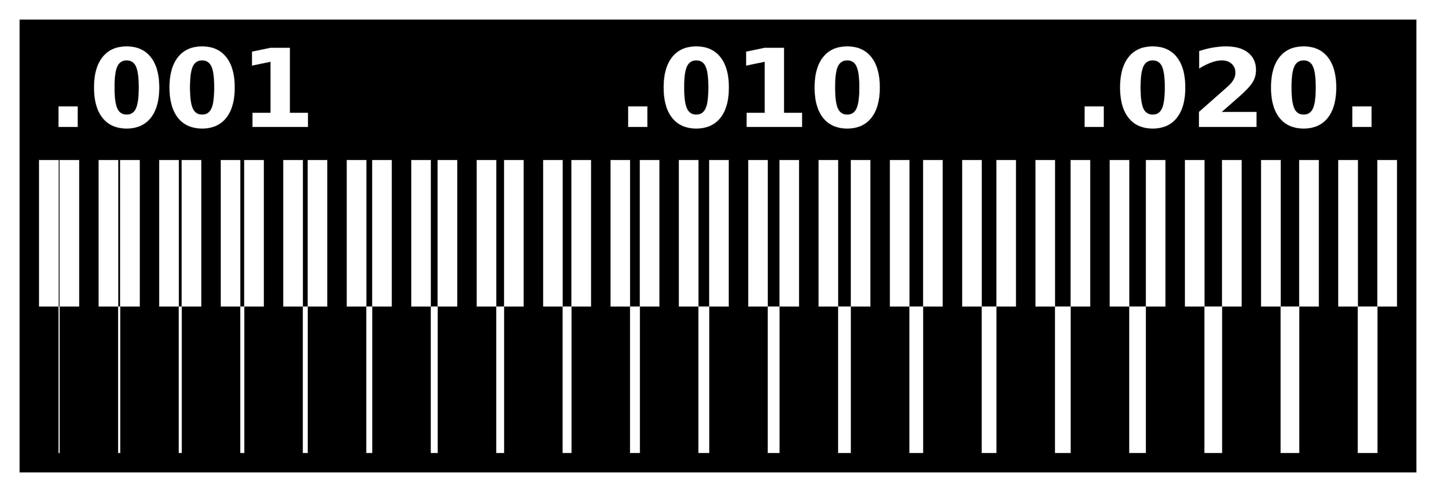
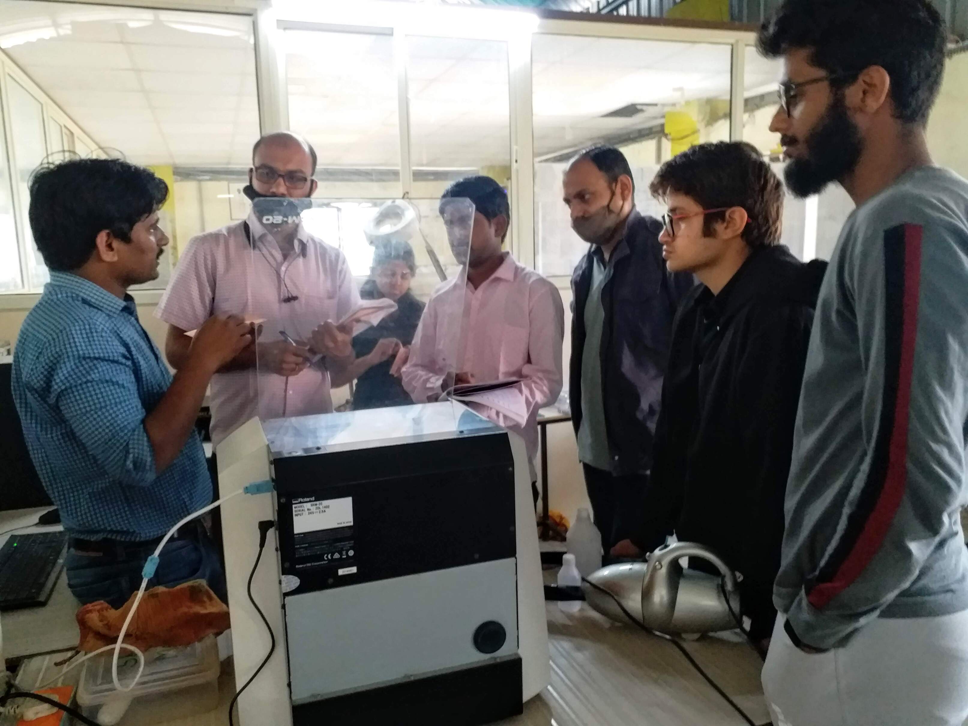 Our local instructor, Suhas Sir, gave us an in-depth introduction to the machine, how to use mods, how to operate the machine, the relevant dos and don’ts etc. We were each given individual 1/64" bits for using in our milling. We then began the group project by milling the test pattern, the results of which can be seen on our group project page by clicking on the link below:
Choosing my wand FabISP
 Before beginning the individual assignment, I asked Suhas sir for some assurance that we will be able to make a FabISP, to which he reassured me and told me that everyone has been able to make FabISPs since the attiny45 based designs came around. He recommended the Brian FabISP design for us to try.
So I naturally didn't take his word and instead decided to try making another FabISP design made by Alex. I'm rebellious like that.
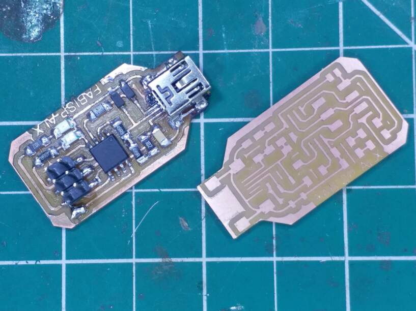
Jokes apart, I actually went through all the FabISP designs on that page, and the reason for choosing Alex's design was two-fold. One was that his design incorporated an actual USB mini socket, which I thought was a better idea than making a board with USB on PCB. And secondly his design was slightly smaller in size than Brian's, which I liked. Also the PCB that was already mounted to the machine only had space for Alex's design (that was actually the only reason, I came up with the other reasons afterwards).

Alex's ISP Traces
Alex's ISP Cutout
Alex's Firmware
Milling Alex's FabISP
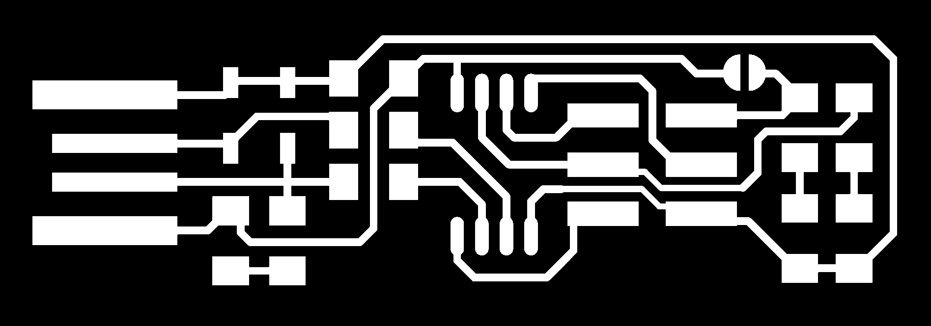
 So I took the traces and outlines png files from Alex's page, but I did not to go through the documentation. That was not the best idea as we will see later.
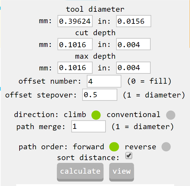
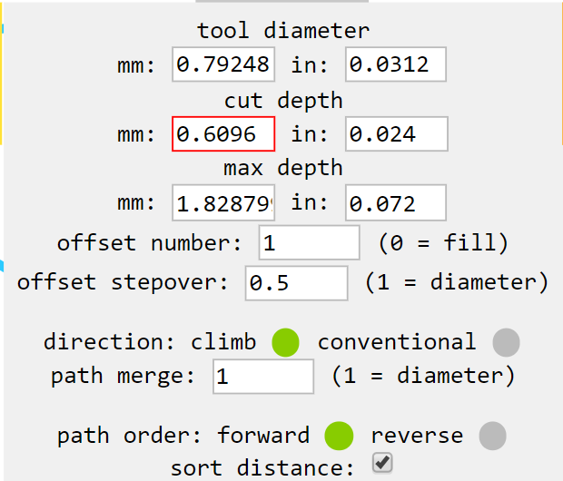
I took to mods on the fablab's PC, and kept the parameters according to the 1/64 inch bit that you can see here.
Mistakes were made
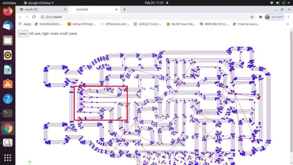
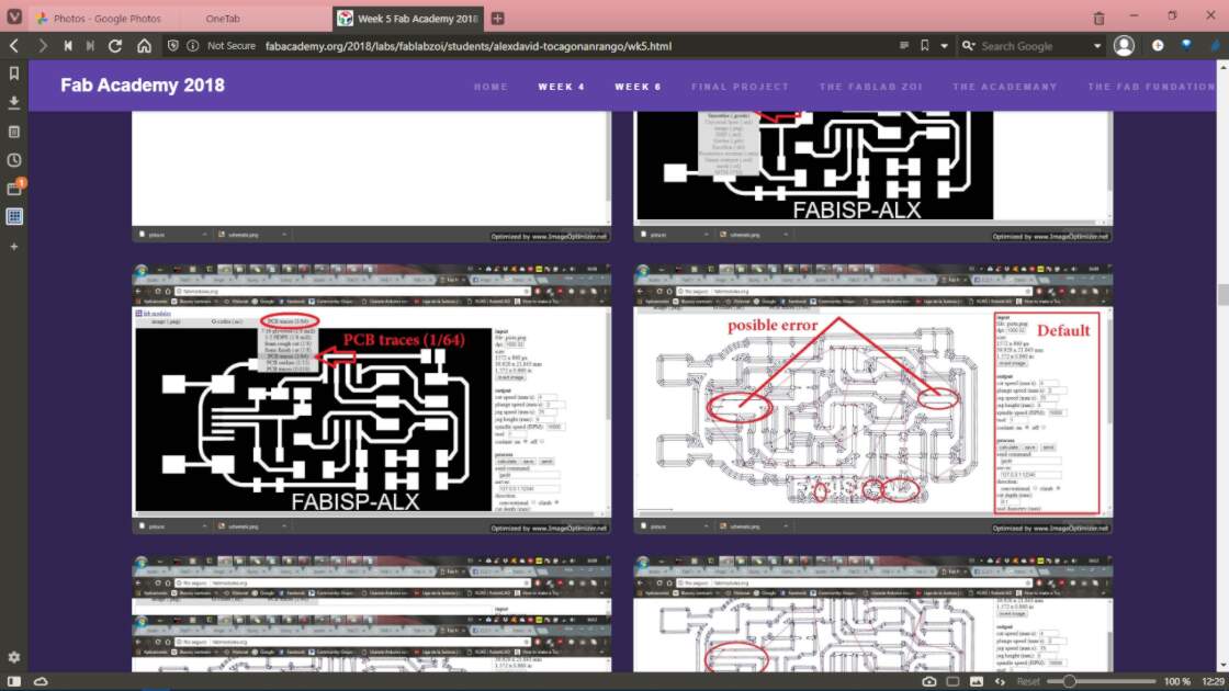
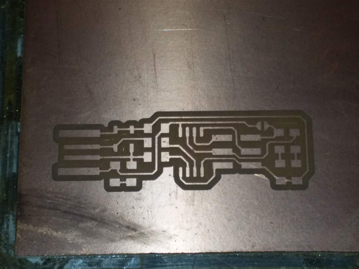
So with the default settings, mods produced a path file that didn't mill all the traces properly. There were two traces fused together that shouldn't have been connected at all. Those were the traces that were used to connect the mini USB socket to the board. I learnt that we should always check the path generated after calculation as it may show us the mistakes even before we mill the PCB.

Fixing the mistakes
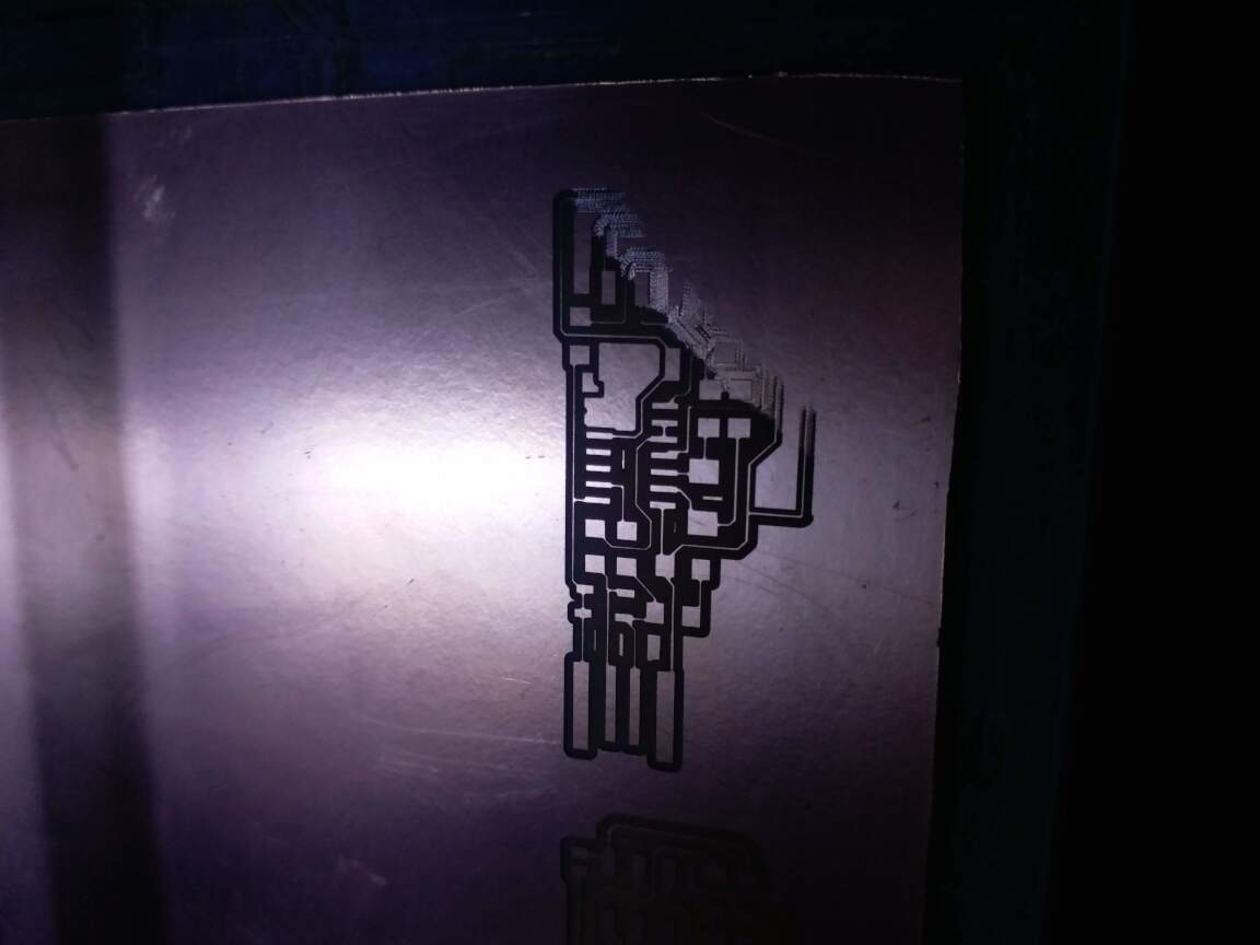
 Fortunately, I knew a hack to fix the issue described earlier. By simply reducing the tool diameter in mods by a small amount, I was able to make sure that the path file separated those traces.
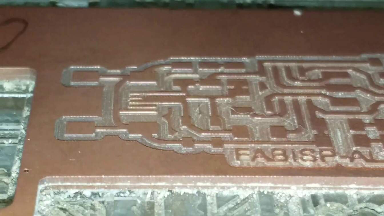
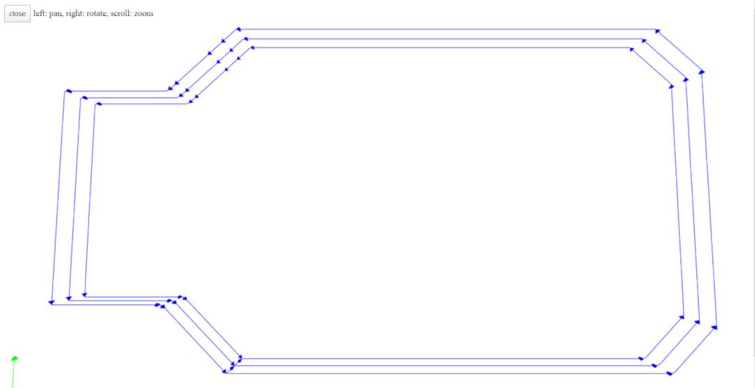
This time, I made sure to check the path generated by the software, and then sent the file to the machine without changing its origin, so that it would make the traces on the existing milled board.
And the result can be seen below:

 Later, while going through Alex's documentation, I noticed that he had faced the same issue while milling the board himself. He tackled the issue by changing the bit diameter as well as the offset value in mods.
Cutting the Board
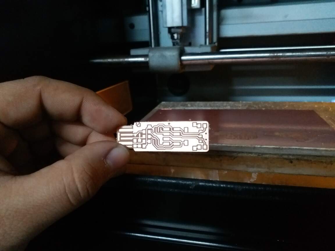
 I then cut out the board using the default settings and a 1/32 inch bit.
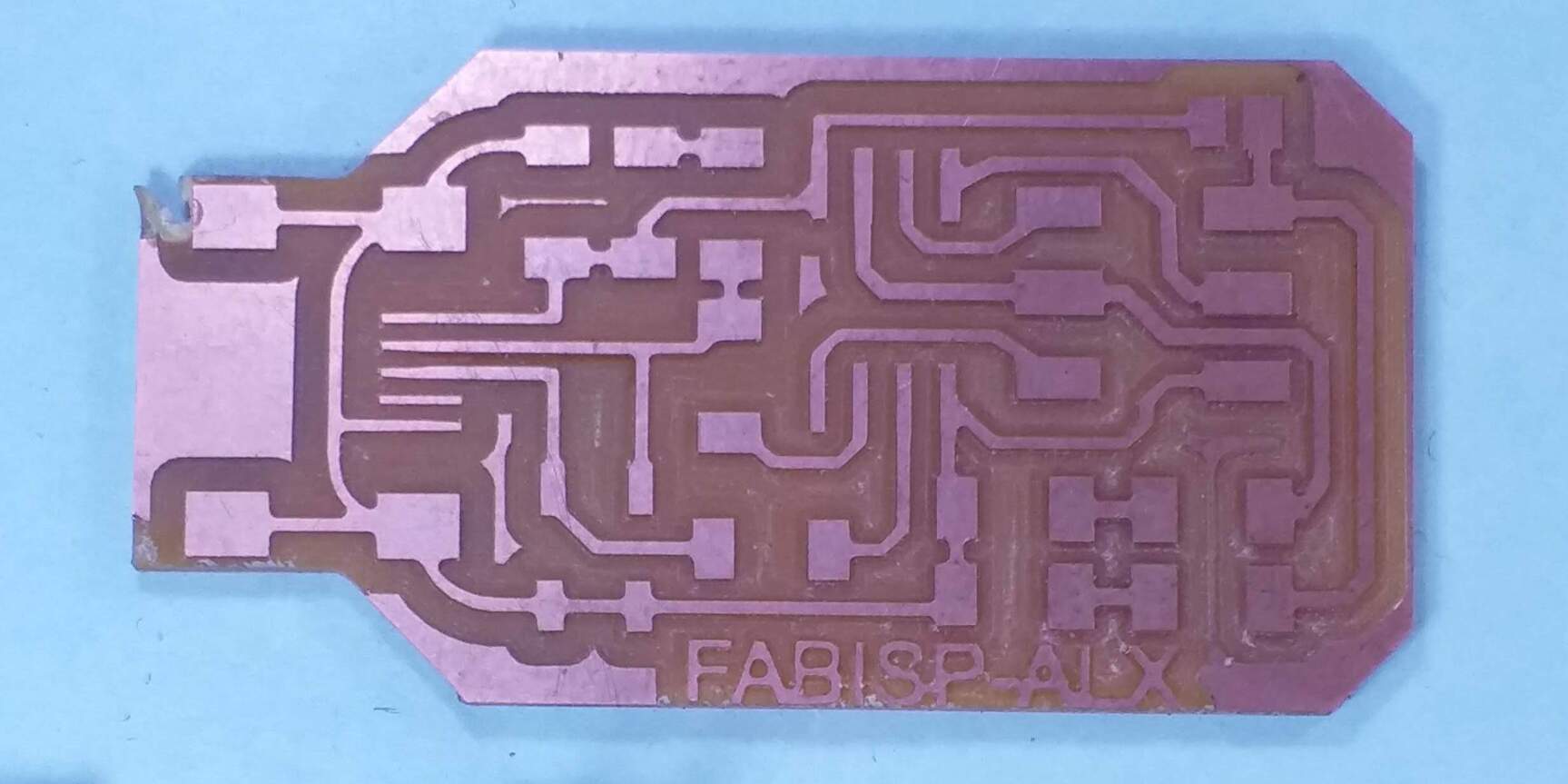
The PCB wasn't stuck down well, so the board moved in the end and drove itself into the bit a little. But I immediately powered off the machine and thankfully the board hadn't gotten damaged too much and all the traces were intact.
And this is how the finished PCB looked like:
Soldering and Stuff(ing)
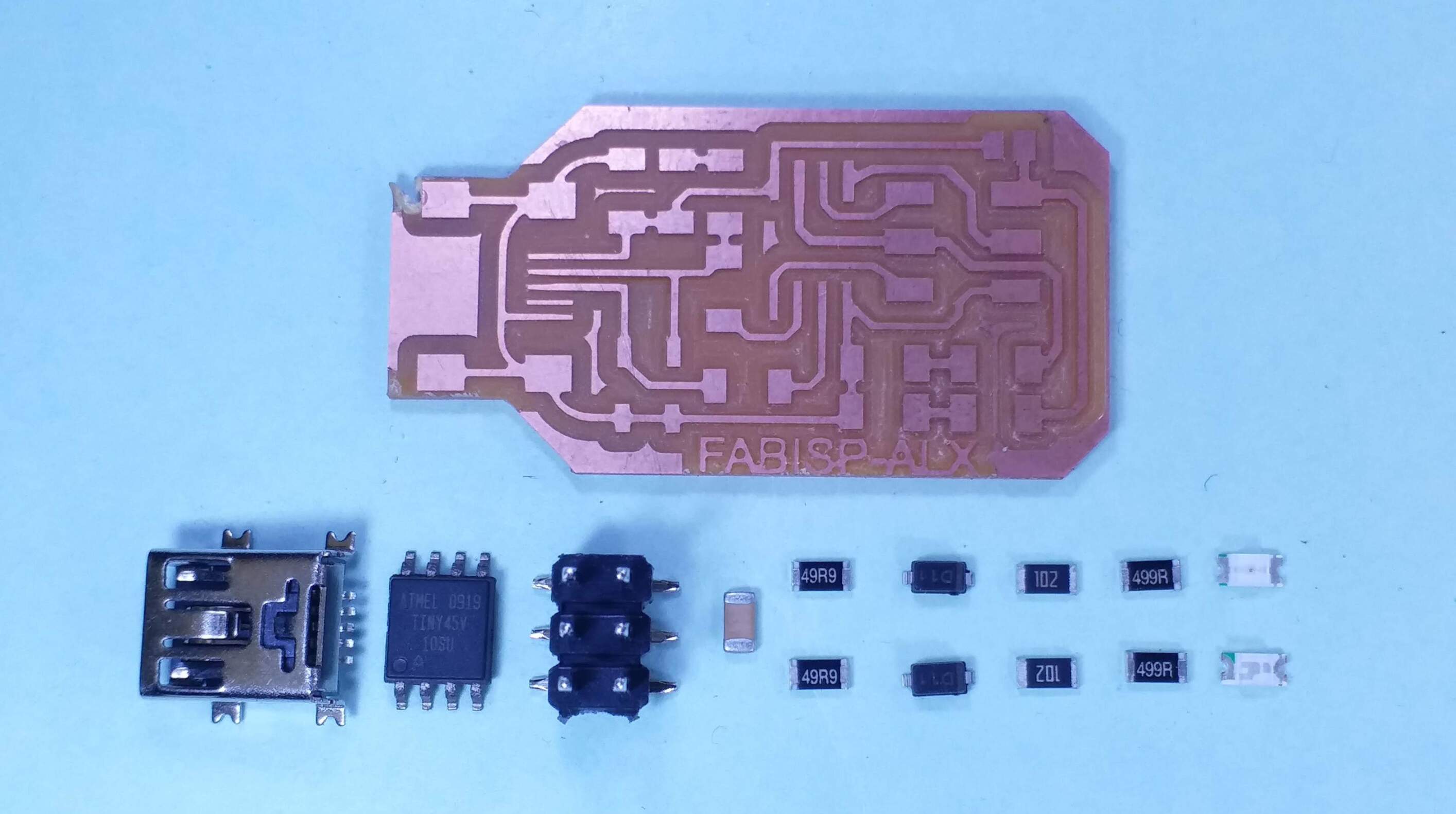
Alex has listed the components required to make his ISP board as follows:
- 1 x Attiny45/85
- 2 x 1 kOhm Resistors
- 2 x 499 Ohm Resistors
- 2 x 49 Ohm Resistors
- 2 x 3.3V Zener Diodes
- 1 x Green LED
- 1 x Red LED
- 1 x 100nF Capacitor
- 1 x 3*2 header pins
- 1 x USB Mini Socket
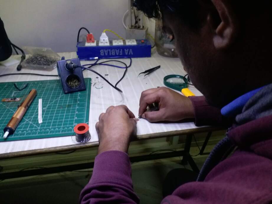
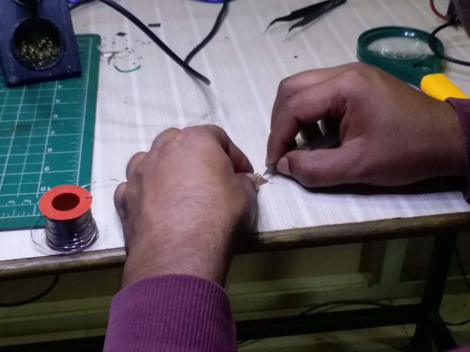
I've had a ton of practice soldering for many projects that I have done over the years. So this part was actually fun for me, and I tried to video document the process, but I repeatedly took the circuit out of frame for better viewing, forgetting that the camera was on. Anyway, I'll attach a sped up version of the video below.
While choosing the components for soldering, I was a bit skeptical about the diodes and whether I chose the right ones or not. I didn't question my selection rightaway and went with the diodes labelled D11. I had no idea how to look up SMD components. This would blow up in my face later. I was also doubting the strength of the connection between the USB mini socket and its PCB traces, but there was little I could do to check the connection except visually.
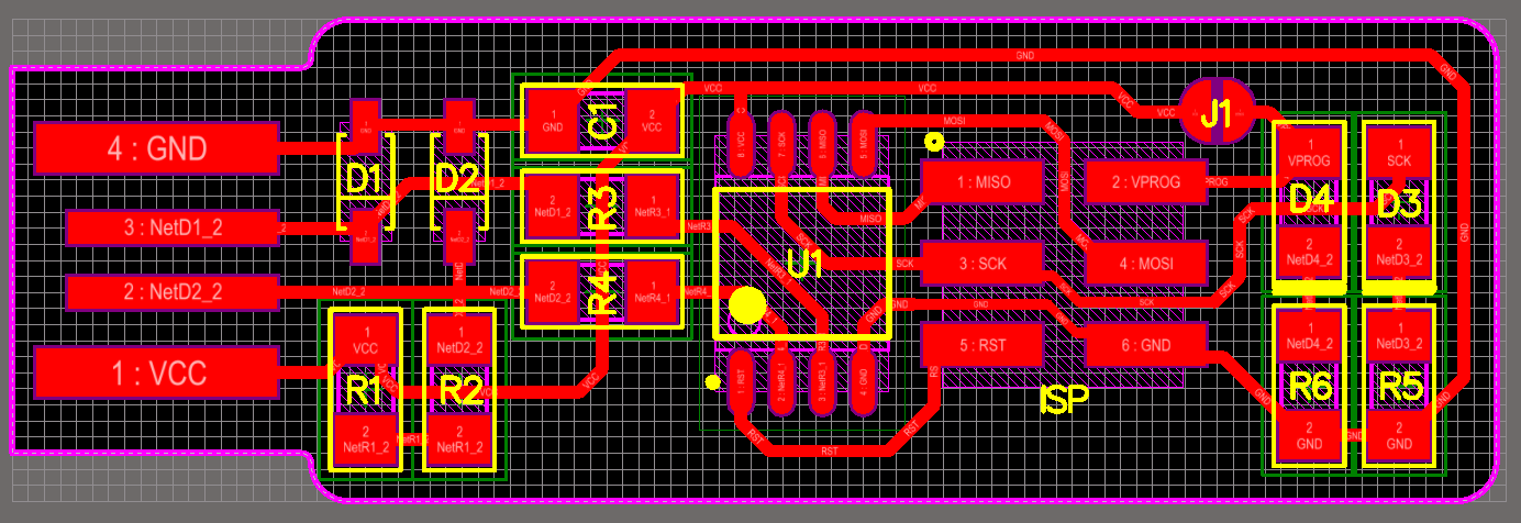
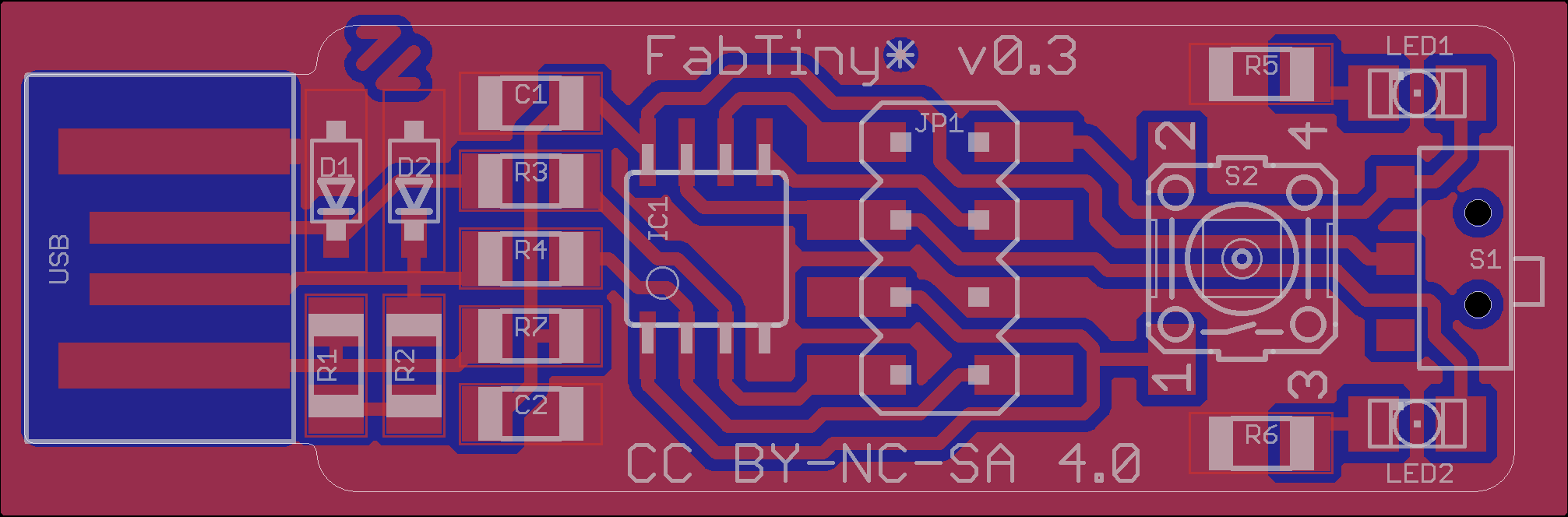
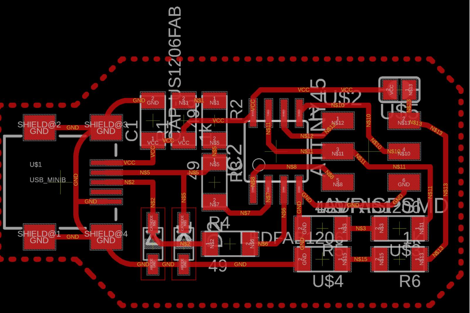 I tried to look at Alex's documentation for references for soldering, but was left empty handed, since Alex had not put up the pictures of the board, which is crucial for info such as where all the polar components (diodes, ICs) go. I had to refer to his schematic, and Brian's documentation, which Alex had used to design his board too. (Update: I realised later that he had attached his BRD files which I could download and then refer to. I will attach a picture from his board design in eagle here as a future reference.)
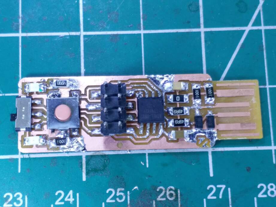
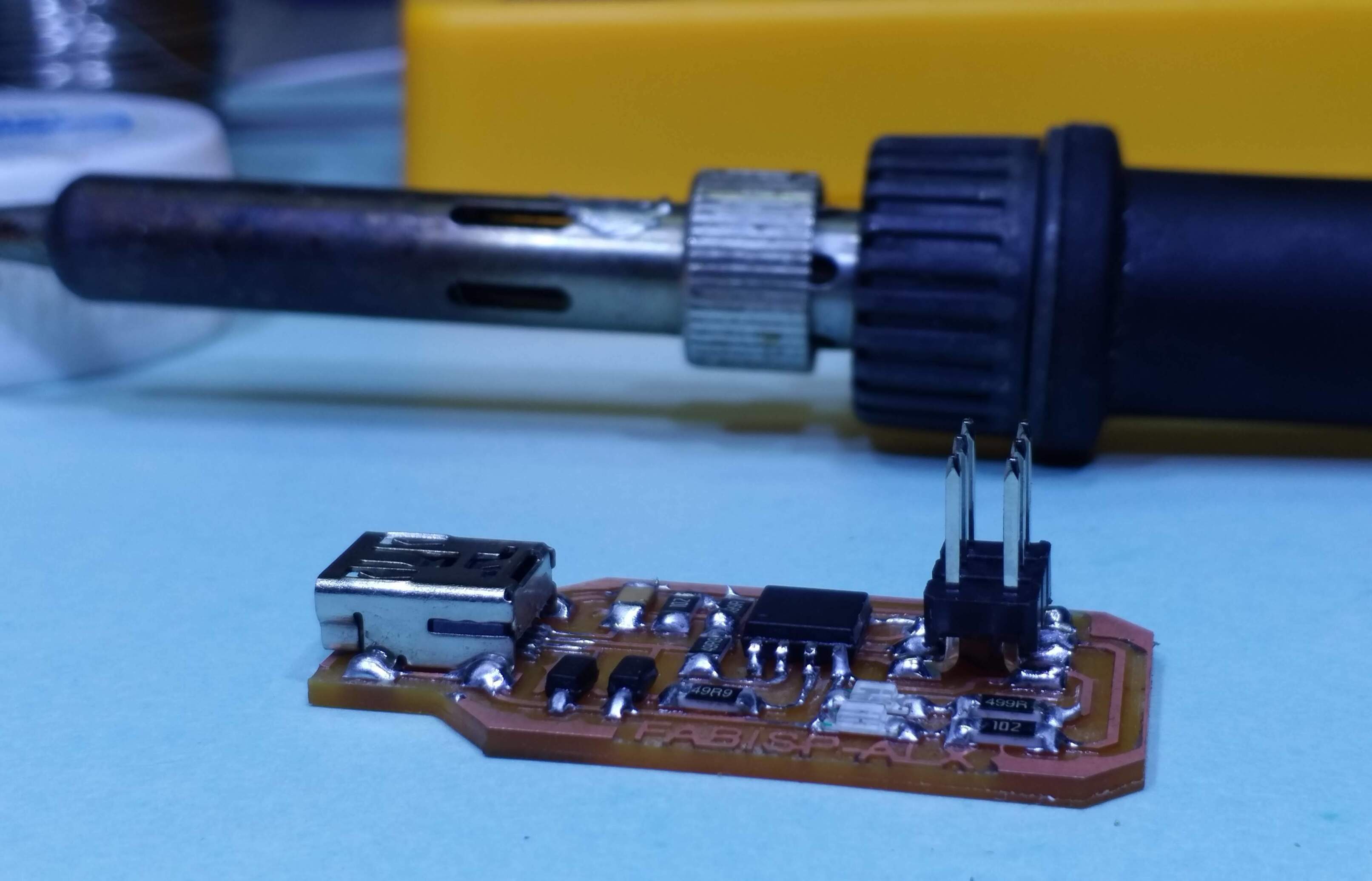
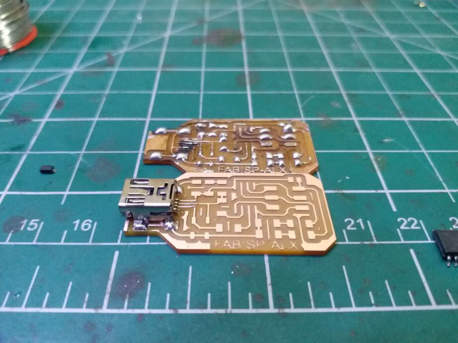
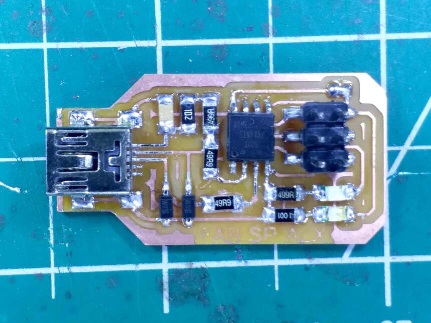
 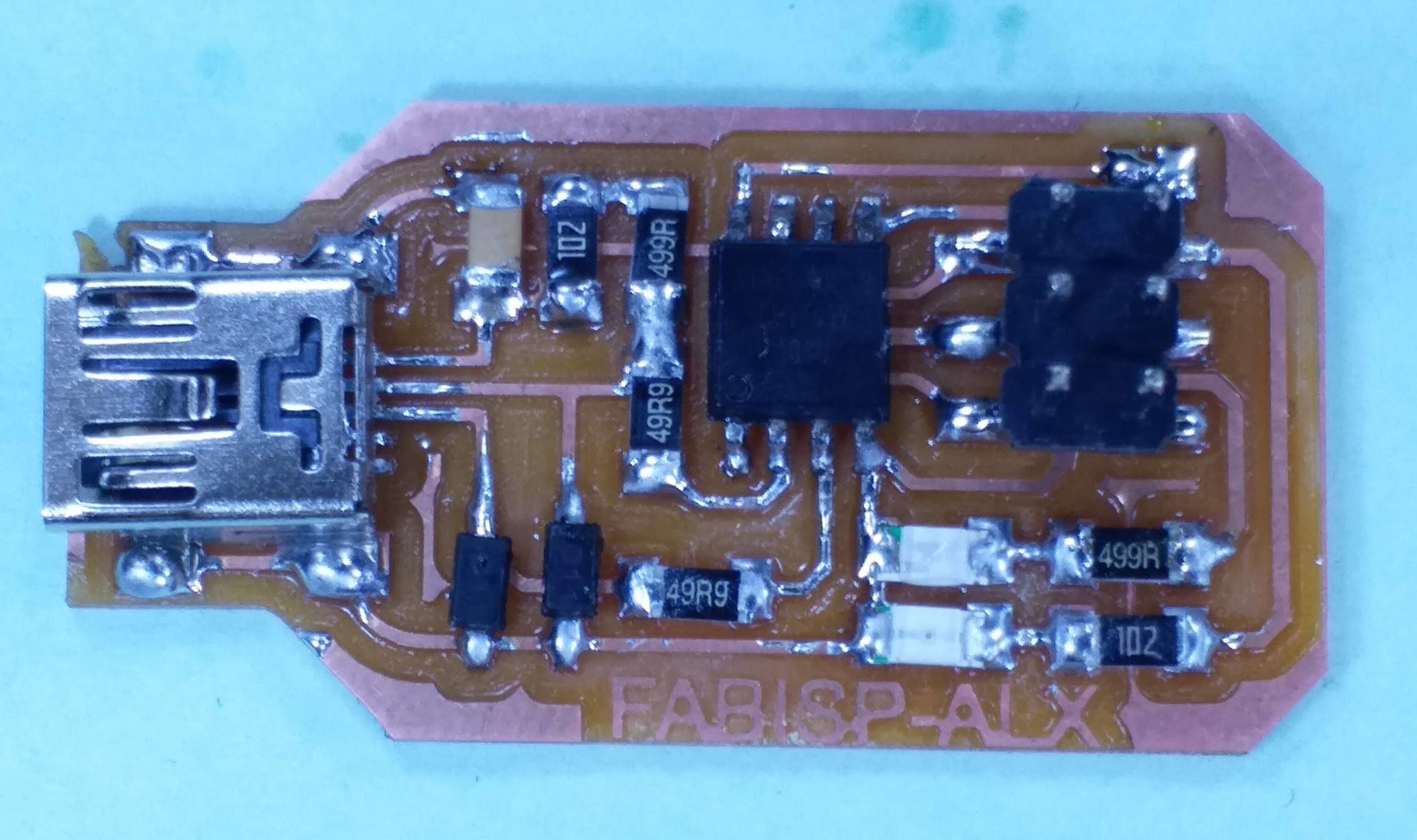 Anyway, after nearly an hour, I was done with soldering my PCB, and here is the result of the finished process. To my future self, and to anyone who is reading this, I have to mention this: Having good quality flux can literally change the quality of your connections so much! I didn't use flux in the past to solder components. But this time, I saw how much difference it makes. Also make sure to have a good quality soldering iron. The Vigyan Ashram Fablab has an excellent Weller Soldering station, which has a pointed tip soldering iron and temperature control, that is perfect for SMD soldering. Also get yourself a sturdy pair of tweezers, a decent multimeter, and make sure you solder in a well lit area. A magnifying lens will make checking for good connection and also looking for shorts very easy.
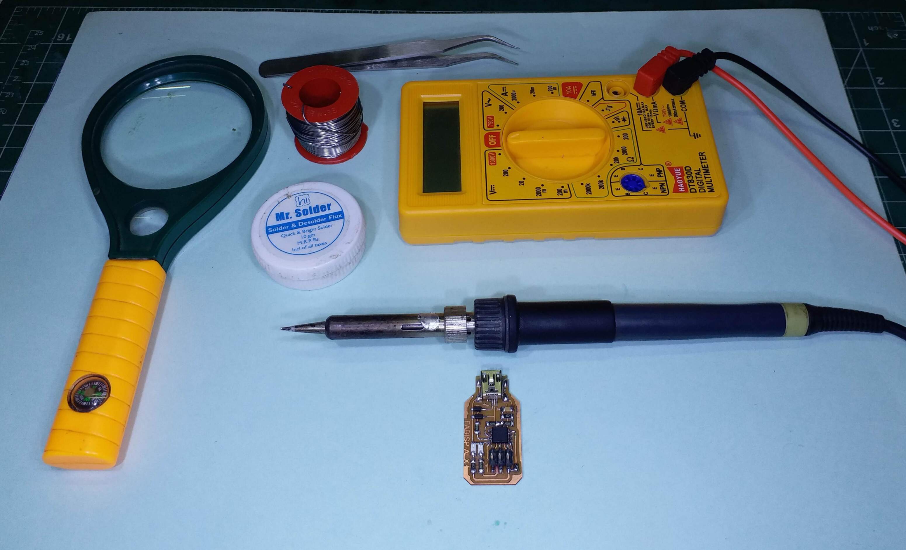
After some thorough investigation of the board for shorts using the multimeter, I moved on to the next step, i.e. flashing firmware.
Software can be hard sometimes
So the thing that I realized this year that I was doing wrong back in 2016, was that I was trying to flash the firmware onto the FabISP through USB. Now I realized how silly that was. Of course the board doesn't get flashed via USB, hello, the thing is empty, how will it understand the signals it received on its pins via USB?
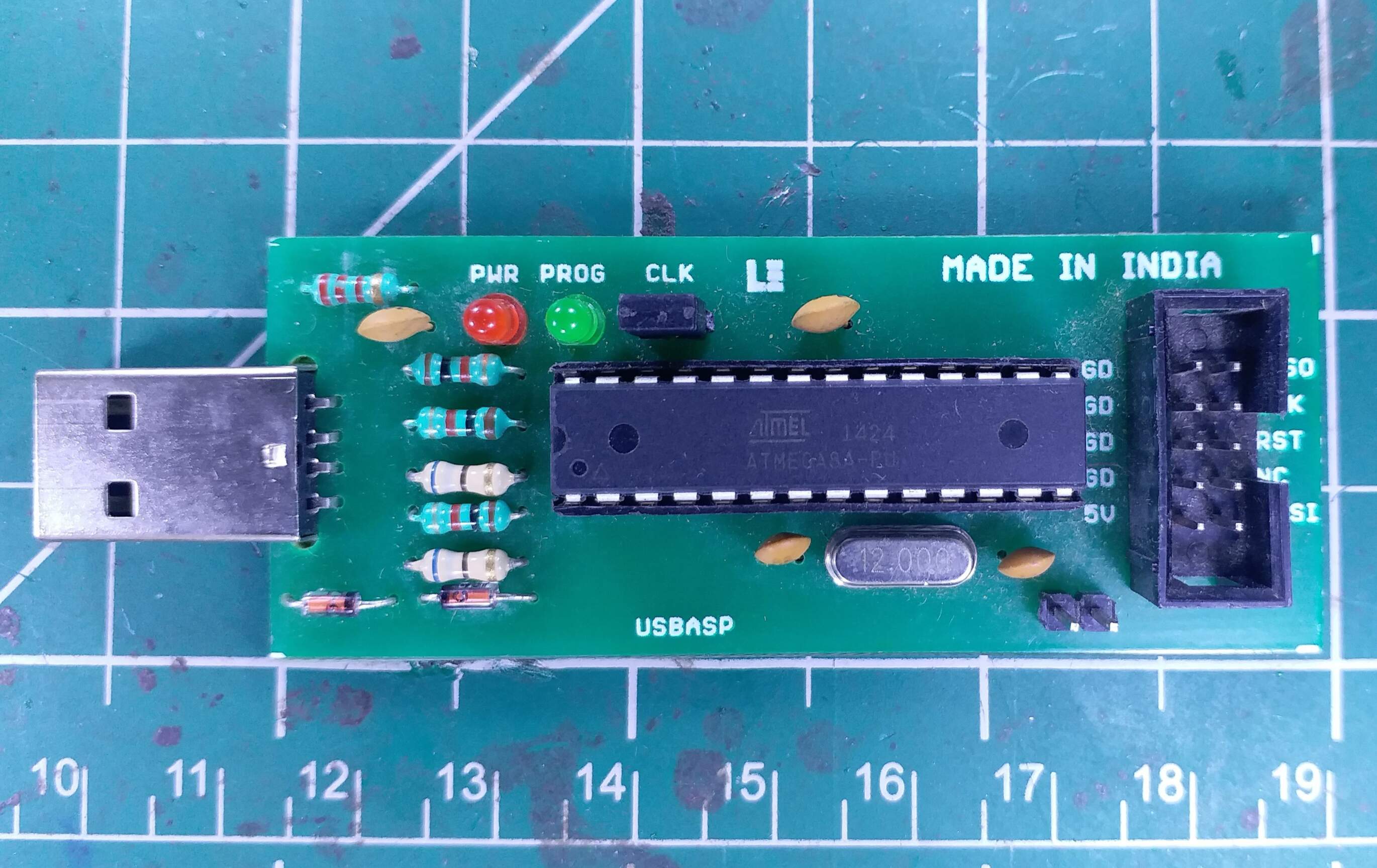
Anyway, I turned to Alex's documentation for looking at how he had flashed his firmware to the board. He mentioned that he flashed his FabISP using something known as a USBasp. Upon enquiring, I found out that our lab also carried a USBasp board that is used to flash firmware to FabISPs.
So I started connecting the USBasp to my FabISP. I was also cross checking Alex's documentation with Brian's Documentation just to be safe. This turned out to be a good idea, since I realised that there is one step that Alex did not mention in his documentation that Brian does, and it is sort of a crucial step. Plus, Brian has documented the entire process fairly well. So I proceeded to follow his documentation instead.
So for flashing the firmware on Windows, I began with installing some softwares. Brian mentions four major softwares that are useful for installing the firmware to the ISP:
- Git Bash: I already had this downloaded from week 1, so I didn't need to do this step.
- Atmel AVR Toolchain: So I'm guessing since Microchip took over Atmel, maybe the name changed, but now you have to log into the website with an account (and if you don't have an account, make one. Grrrrr.) and look for the AVR 8-bit toolchain. The version at the time of making this documentation was v3.62 for Windows. It downloads as a zip archive, and when you're asked where to extract it, make sure to choose C:/Program Files as the path of the installation.
- GNU Make: I downloaded v3.81 of GNU Make from Brian's page. This is a tool for converting code into executables based on settings mentioned in a makefile. IT downloads as an exe file, and you can just leave the default settings here.
- Avrdude: avrdude is basically a software that talks to AVR processors and can manipulate data in the ROM and EEPROM of these chips using the ISP. This downloads as a zip archive as well, so you need to extract it in the "C:/Program Files" folder of your PC.
Atmel AVR Toolchain: When I extracted the file from the zip archive, it comes in the form of a folder with the name: avr8-gnu-toolchain-win32_x86.
I had to get rid of the _x86 part at the end to make the next step work.
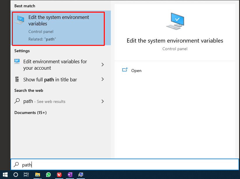
After this, I had to add the paths of these softwares to the PATH file of our operating system. On windows 10 you can directly search "path" on the start menu and you should get this:
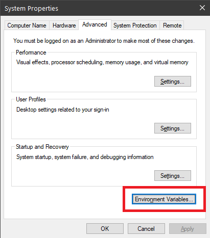
After pressing enter, I was taken to this window, where I clicked on Environmental variables:
After that I was taken to this window, where I had to choose the entry labelled Path. I clicked on Edit as highlighted below.
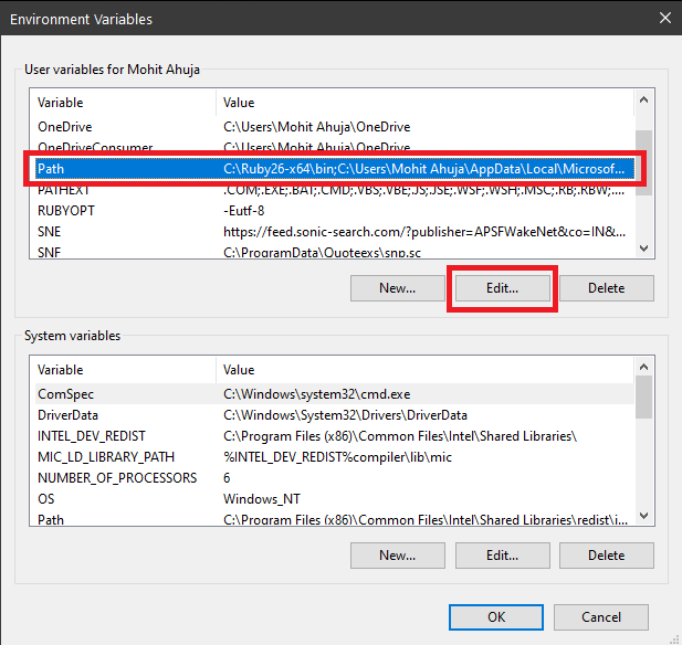
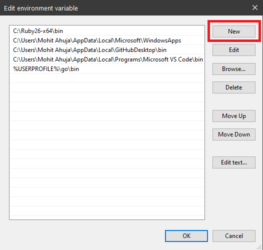
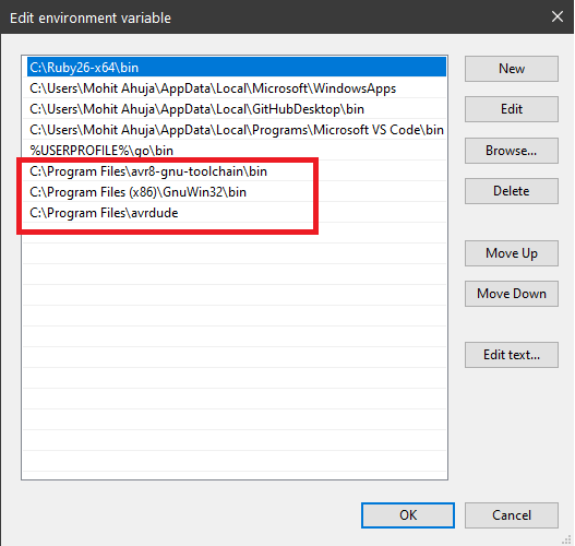
Doing so took me to this window, where I had to add three new entries for the three new softwares that I installed. The three entries were:
- C:\Program Files\avr8-gnu-toolchain\bin
- C:\Program Files (x86)\GnuWin32\bin
- C:\Program Files\avrdude
Checking to see if everything works
After this was done, I proceeded to check the installation of the softwares as suggested by Brian. Here are the commands that were used to check the various softwares and their respective outputs:
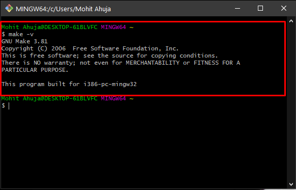
- Make: To check if make has successfully been installed, I typed
in a git bash terminal and the following was the output.
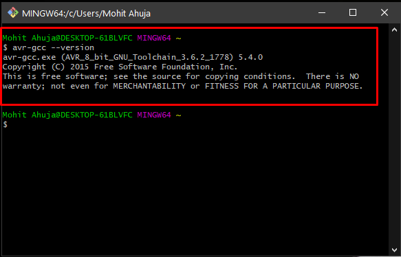
make -v - AVR-GCC: To check if our AVR Toolchain has been correctly installed, I used the command
and got the following result:
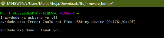
avr-gcc --version - Avrdude:To make sure that avrdude has been successfully installed, and is working as expected, I took the programmer i.e. the USBasp and connected it to the computer, and then proceeded to run the command
and this was the output:
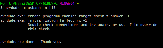
avrdude -c usbtiny -p t45 - Then I realised that since my programmer is a USBasp programmer, this command needs to be changed to accomodate for the different programmer, so I tried this command
which resulted in this:
avrdude -c usbasp -p t45
After checking all the softwares, I was ready to move on to the next step, ie. Flashing the Firmware.
Flashing Firmware
Now that I had installed and checked all the necessary softwares for this step, it was time to flash the board, so I hooked up the board to the USBasp according to the ISP protocol.
Brian had the firmware linked on his page, and after confirming that Alex was also using the same firmware, I proceeded to download it from his page.
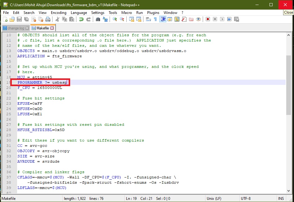
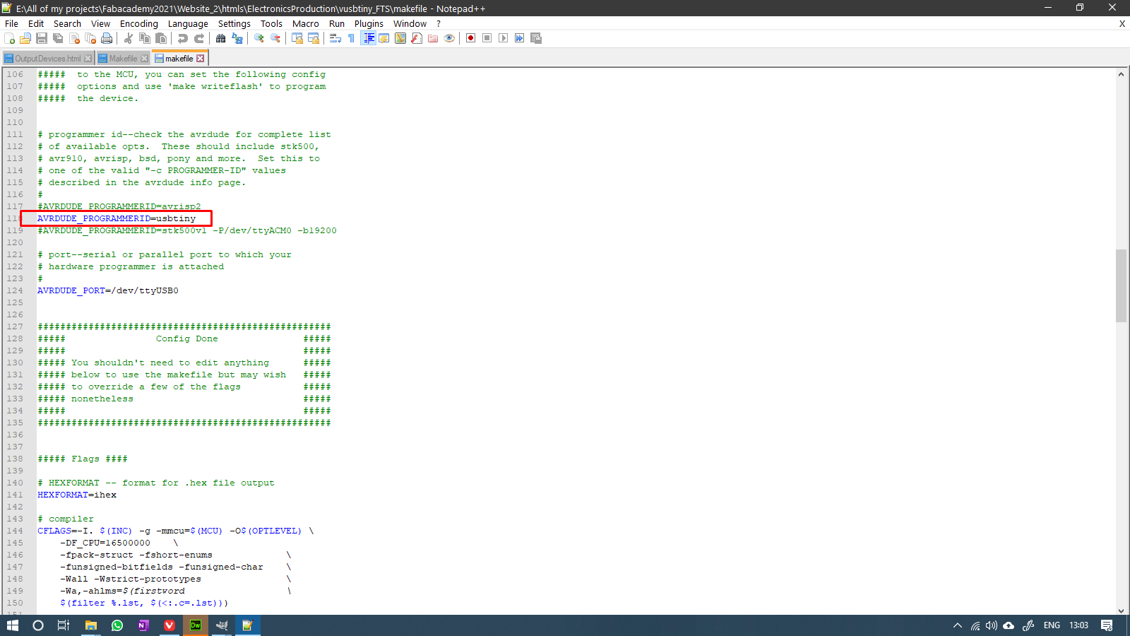
After downloading the firmware, I proceeded to open the makefile in Notepad++, and changed the programmer parameter from usbtiny to usbasp, since I realised in the previous section that the programmer that I am using is different ffrom Brian's. This is what the makefile looked like after the change:
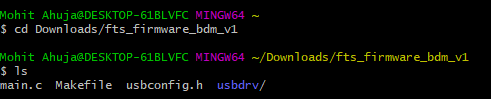
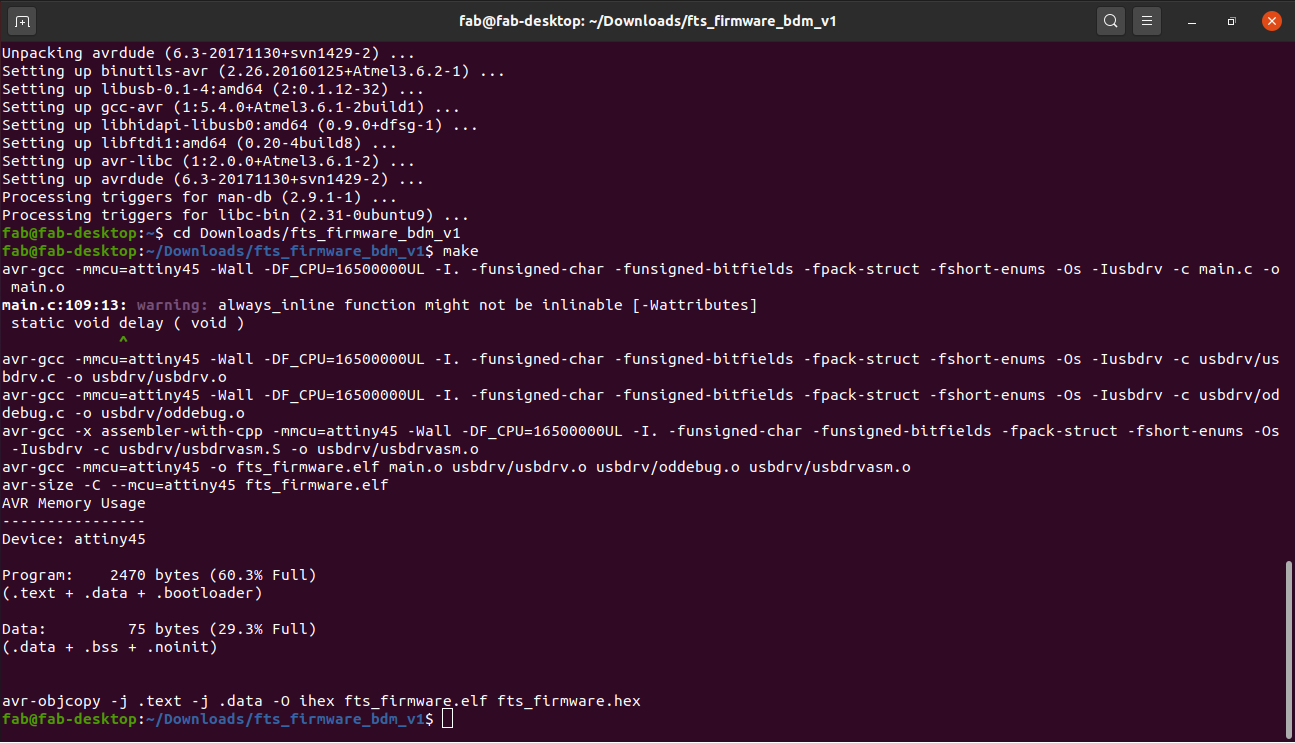
After that, the first step to begin flashing the firmware, was to navigate to the firmware's folder on my drive. It was in the Downloads folder with the name fts_firmware_bdm_v1. I had already extracted it from its archive. I navigated to the folder using the command
Then I also checked the contents of the folder to make sure I was in the right one using the following command
which resulted in the following outputs
After that, I ran the following command in the same terminal:
and this was the outcome of that:
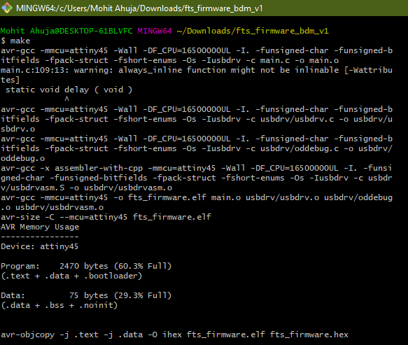
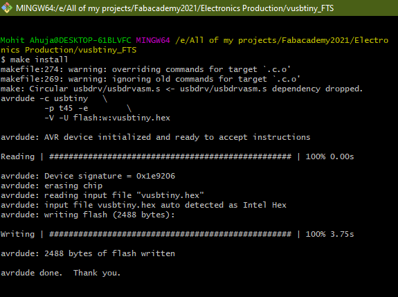
This step generated the hex file fts_firmware.hex that will be written to the attiny in the next step, which was running the following command:
and this was the outcome of that:
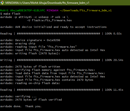
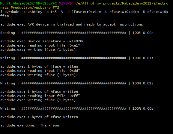
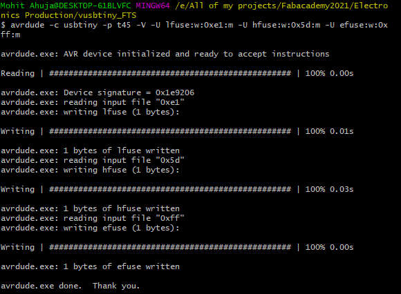
After the board flashed without any issues whatsoever, I entered the following command to configure fuses:
and this is what became of that:

A video of the USBasp burning the fuses to the FabISP Board:
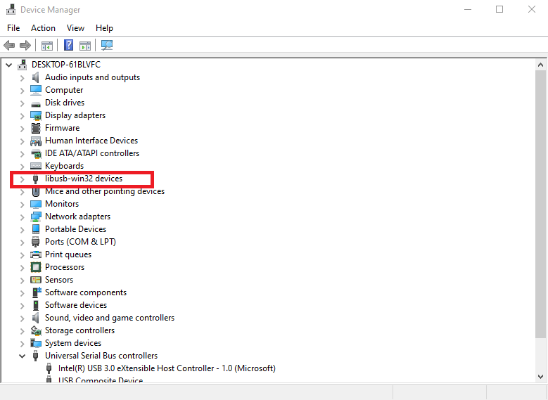
After this step, Brian recommends checking if the board gets recognized by the computer as a USBtinyISP device or not, but Alex did not mention this step. And when I tried to check if the board is recognized by the computer, I got nothing. I decided to proceed with the next step anyway to burn the reset fuse, essentially making the board unable to reprogram. To do that, I ran the following command:
and this was the resulting output:
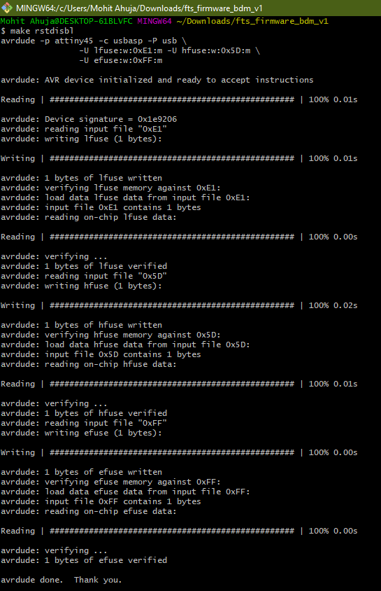
With this, all the steps for flashing the firmware were done.
Troubleshooting
The first thing I tried after having done all the steps, was to try and connect the board to the computer, to see if the computer recognized the board as an ISP or not. Unfortunately, it did not do so.
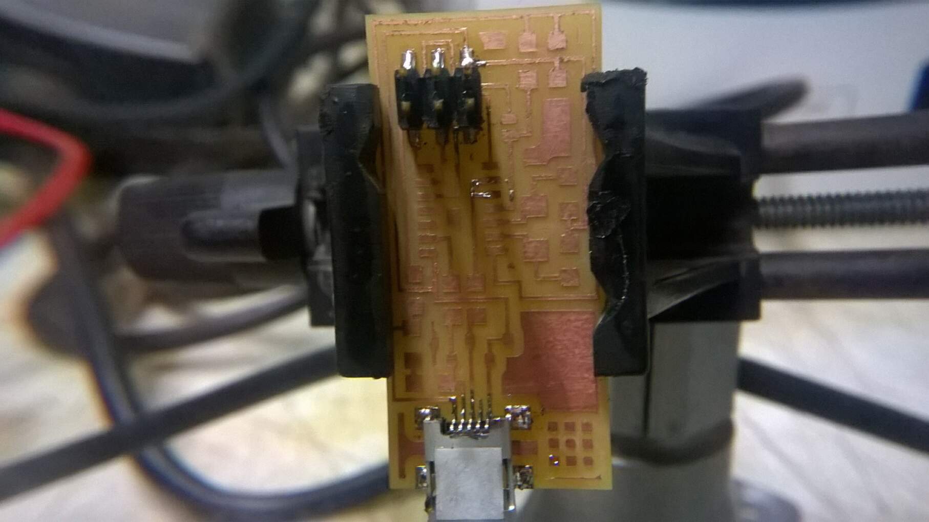
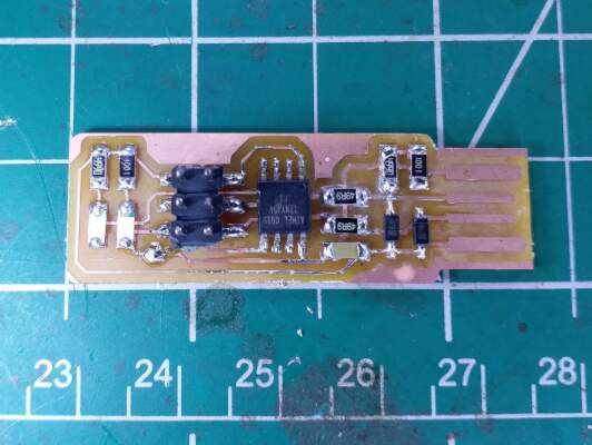
This scared me, and I went straight to my first suspect, i.e. the diodes. Turns out that the D11 diodes were not Zener diodes at all, but Schottky Diodes. I then decided to setup a simple testing rig using a perfboard that allowed me to test different diodes that were there in the lab, since finding them from their labels was proving to be very hard. This is what the setup looks like:
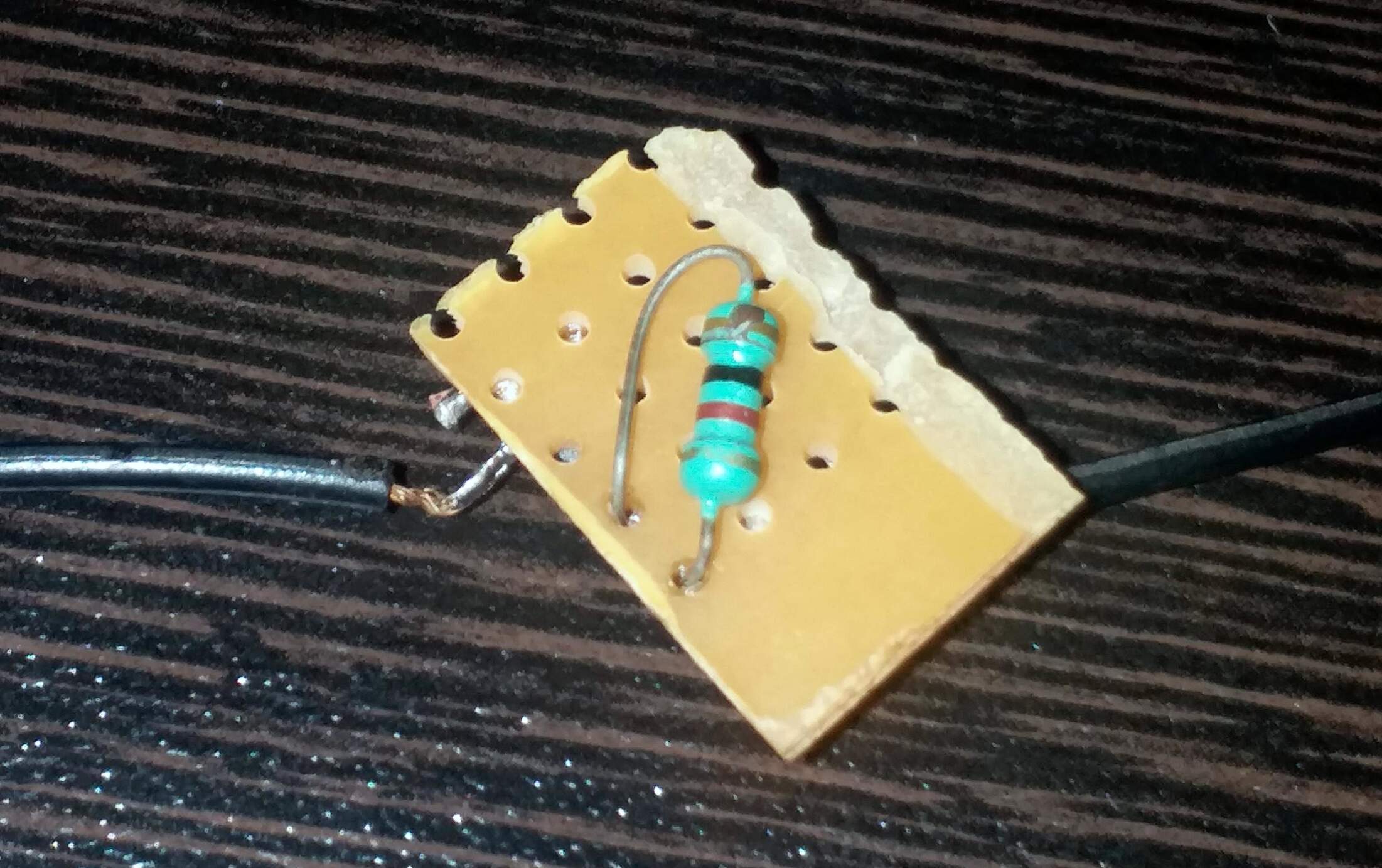
Essentially what I did was this: I created a series connection between the alleged diode and a 10Kohm resistor. I followed the recommendations given in this video:
I applied an external voltage of 5V across the series circuit and measure the voltage acroos the diode. If it was a 3V Zener, it would have given a voltage close to the rated value.
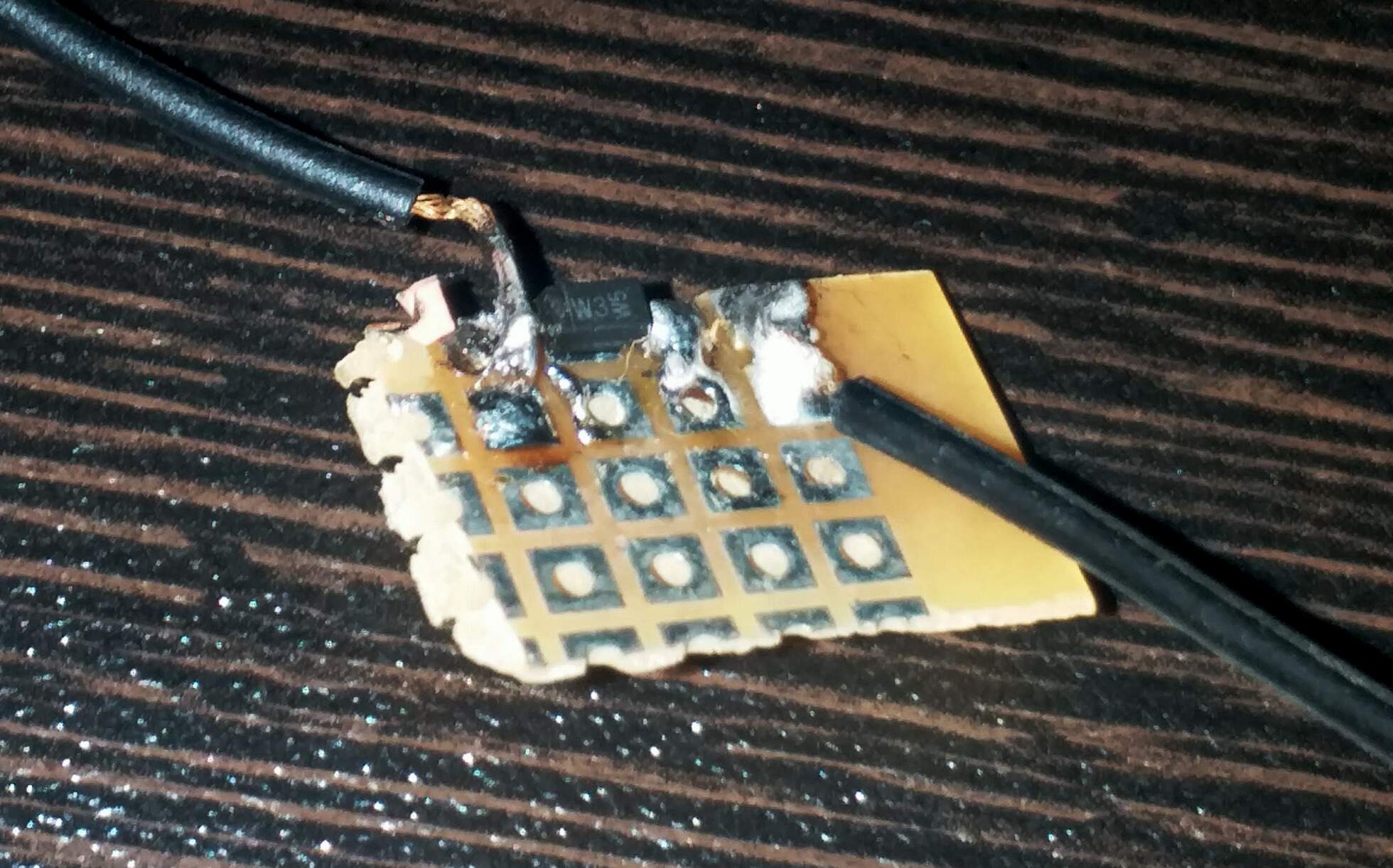
I proceeded to check the D11 diode on this rig, and found that it gave a voltage of 0.6V across its terminals, which was nowhere near the 3V that I was expecting. I replaced the diode with one labelled W3W5, as seen below:
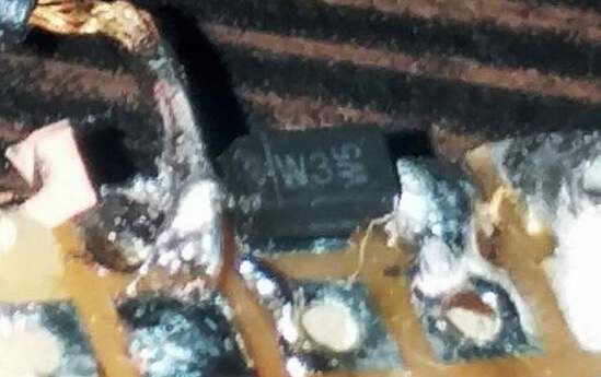
which turned out to be the one, since it gave a voltage of 2.9V, which is very close to the expected 3V. I proceeded to desolder the D11 diodes from the board and install the W3W5 diodes instead. But even after doing that, the board did not get recognized by the computer. I also looked for shorts on traces or the IC, but found none. I could not fix the issue after many tries.
Overcompensating Trying other FabISPs

The wand indeed chooses the wizard. In my case, the wand that I chose wasn't meant for me. So I had to abandon my very beautifully made Alex's FabISP.
Facing this failure, I decided to do something that helps someone in the future while choosing the FabISP that they want to make. I decided to do a comparative analysis of different FabISPs and how difficult or easy it is to make the different ISPs. So I chose four different ISPs to make, which are:
I think Sean's FabISP deserves a special mention for an amazing idea and an even more amazing implementation and documentation. I request anyone going through my documentation to go through his too.
Anyway, I began my investigations by milling the circuits for the different ISPs. The parameters used were the same as before. Here were the results of that:
Alex's and Brian's FabISPs' milled traces.
Valentin and Zaerc's FabISPs
You might notice that Valentin's PCB did not get milled properly. This happened because the bed leveling of the machine was not proper and hence the right side of the bed was slightly lower than the rest of the machine. This led me to eliminate Valentin's ISP from my analysis, since I didn't have enough time to mill the PCB again.
The next slideshow shows the process of stuffing and soldering Brian and Zaerc's PCBs.
Loop continuously
Show frame counter
Alex's FabISP
For Alex's ISP, I decided that I will first try to recycle the components of the board that I had built before. For that I took the help of the Hot Air Soldering/Desoldering station. It is a very dangerous tool, so I don't recommend using it unless you want to quickly desolder some components. But be very careful, because I wasn't and I burned my finger a little bit (nothing serious though). This is what came out of that process. Notice that the diodes are differnt this time, otherwise all the different components are exactly the same.
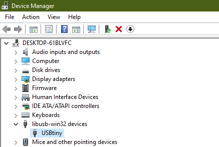
I did this because the microcontroller had been successfully flashed, and I wanted to check whether there was anything wrong with it. Incase it wouln't work, the plan was to replace the IC with new one and flash it. Luckily enough, I did not need to do that, because my ISP got recognized as a USBtiny as soon as I connected.
My thoughts about Alex's FabISP:
Trying to make Alex's FabISP, here are the thoughts that I have about the entire ordeal:
- The design is compact, but the milling of the traces requires you to tweak and tinker with the settings of mods to produce them successfully.
- Soldering the USB mini is quite a task, and not recommended for beginners.
- Alex's documentation is not smooth for navigating, and lacks in crucial detail in some steps, and some steps are skipped.
All things considered, it is a nice challenging design for someone looking for one. But I would not recommend this to be someone's first ISP choice. On some occasions I had to parallely refer to Alex's and Brian's documentations to check something regarding Alex's design and documentation.
Moving on to the next design, we have...
Brian's FabISP

Brian's FabISP Traces
Brian's FabISP Cutout
Brian's Firmware
Brian says on his page that his design is a stripped-down, essenstials only version of FabTinyStarISP (I made this too), and that is a very apt description of what the FabTinyISP is. Brian's documentation is the gold standard for documentation. Very well laid out and detailed steps, describing almost every possible issue and process needed from start to finish, and it takes very little effort to understand it. It took me the least amount of effort to build this ISP, and the process for flashing the board was exactly the same as Alex's ISP(since Alex derived his design from Brian, so that makes sense), so I didn't document it separately. One noteworthy thing that needs to be done for Brian's board, which he also documents well on his page is that you have to scrape away some extra copper that ends up shorting the data lines. Here is Suhas sir showing it to us:
Another thing that I did differently with Brian's FabISP was I used Ubuntu which was installed on one of Fablab's PCs and tried the steps for Linux operation systems from Brian's documentation.
There were a few steps that I needed to follow to accomplish this:
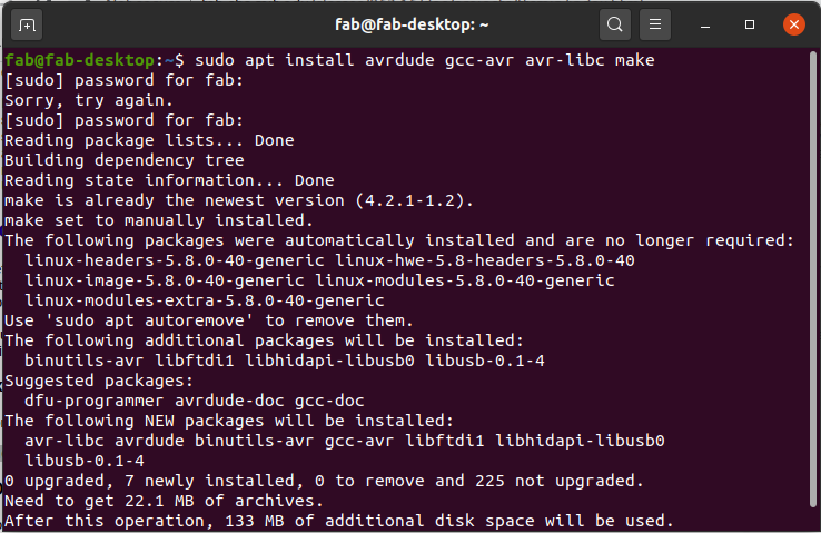
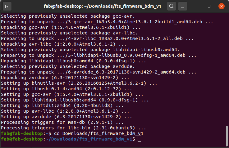
- First I had to install make, the avr toolchain and avrdude for Linux and I did that by typing the following command:
- After that I had to navigate to the folder of the firmware inside the terminal by using the following command:
- After that it was the same as the rest of the commands, with the notable difference being that I didn't need to edit the makefile because I was using a FabISP made by a previous year student to program my ISP. I began by typing the command:
- After that I ran the commands:
- After all of the steps to burn the firmware were successfully executed, I ran the following command to check if the computer recognizes the ISP:
make fuses
make rstdisbl
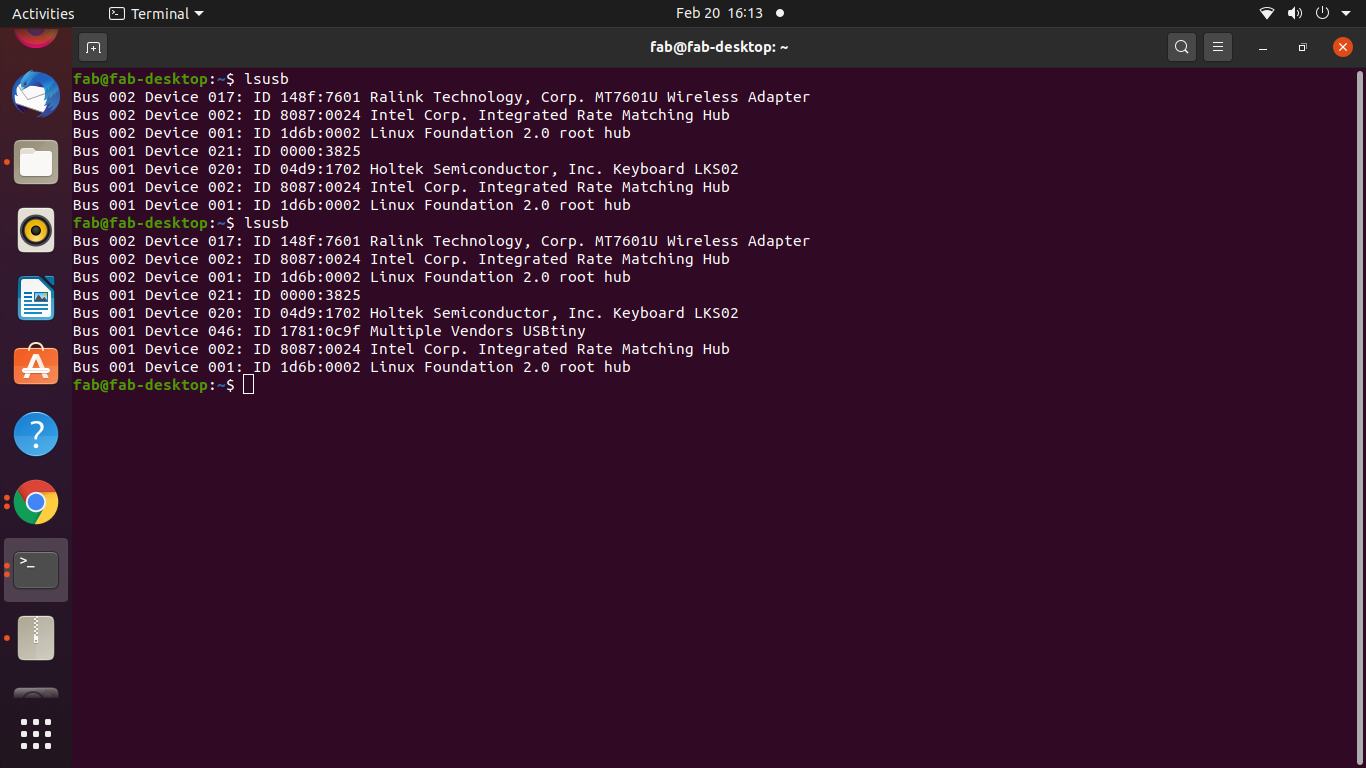
That "Multiple Vendors USBtiny" in the terminal is proof that the FabISP has been successfully flashed.
Thoughts on Brian's FabISP:
I have expressed almost all of my thoughts about Brian's documentation and design in the beginning of this section, but I'll reiterate them here for the sake of continuity.
- The design is well made with very well laid out pads for all the components. They say that a good design uses negative space to its merit, and this is certainly the case with this PCB design. The components are spaced out enough that it will be easy for someone soldering for the first time to make this. Though you should keep the order of the components according to their size in mind, i.e. ideally one should solder the largest components first, and then solder progressively smaller components as you go along. Highly recommended for beginners.
- The USB on PCB is the one thing that I might not be the biggest fan of, and it is because you have to do some funky things to fit it within the USB port of the computer, and also the contacts have to be covered with solder that makes it blobby and unreliable, but if you don't cover it, then the traces will get corroded by the atmosphere. It can be easily fixed tho, by simply soldering a USB male port directly onto the traces or something, so if one prefers to have a USB port, they have this option.
- Brian's documentation is an absolute delight to read, and he spares no detail. Highly recommended for beginners.
The last but not the least ISP that I tried was...
Zaerc's FabTinyStarISP

Zaerc's ISP Traces
Zaerc's ISP cutout
Zaerc's Firmware
Zaerc's FabISP has the most unique look of all the ISPs based on the attiny45. With the extra slider and push button, I was very excited to see what their purpose is. Turns out that the slider switch decides whether the board being programmed using the FabTinyStar will get the power from the ISP or will the board need an external supply, while the momentary switch/pushbtton helps to physically reset the board being programmed.
Zaerc also links to pages that have documented the process of making the FabTinyStarISP, and out of them, one of my favourite pages to read was SheekGeek's Page, who has also done a very good job at documenting the process including things that could go wrong. I actually referred to both SheekGeek's and Zaerc's Pages simultaneously.
I decided to use the Brian's FabTinyISP that I had just finished making to flash this board. This is how I hooked up the board:

With this board, the process of flashing the firmware was slightly different from Brian and Alex's boards, but since Brian has derived his board from Zaerc's design, I thought this process will work for the other boards too. Anyway, so the first difference between this and other boards is the firmware itself, which is linked on Zaerc's website in the Downloads section. You can click on this text to directly download it..
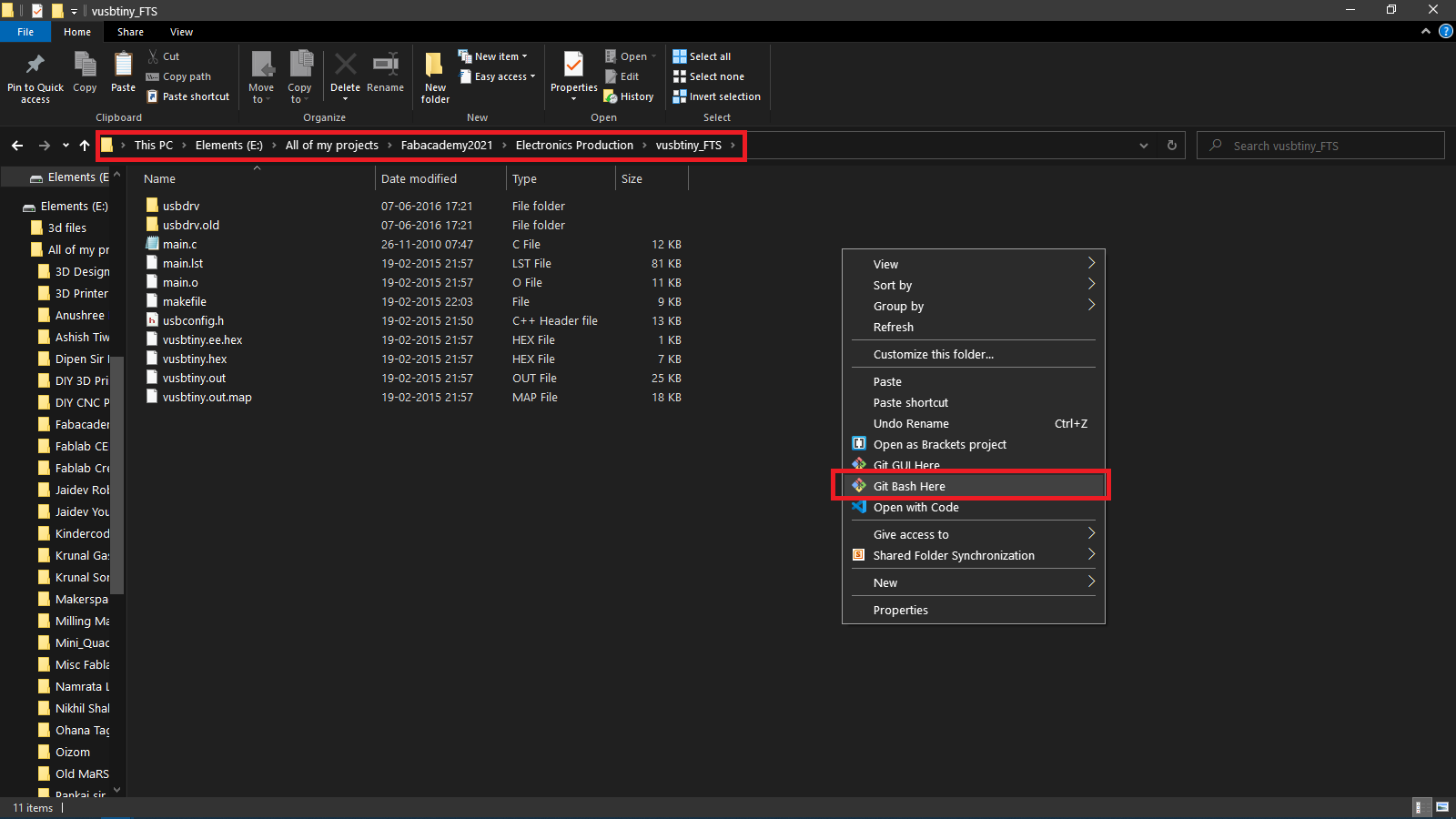
After downloading and extracting the firmware, I navigated to the firmware folder and then right clicked and selected "Git Bash here". This was a shortcut in order to avoid navigating to the folder in the Bash terminal.
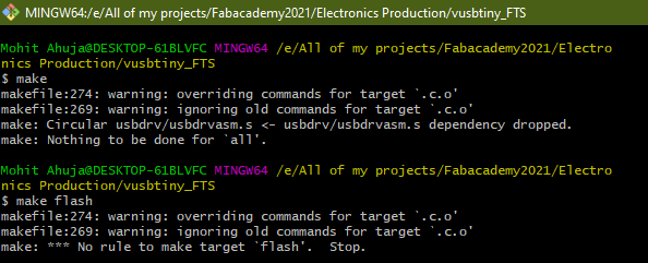
After that, I tried my theory that the steps used to flash the firmware to Brian's board should also work with Zaerc's ISP, but I was quickly proven wrong, as you can see from the below errors:
After failing to flash the board using Brian's steps, I proceeded to refer the documentation for flashing the firmware made by Zaerc. I realised that I wasn't going to be able to follow it as it was meant for only Linux users. But I had also seen that the Git Bash terminal acts like a Linux subsystem, so I decided to try the steps anyway.
I ran the command:
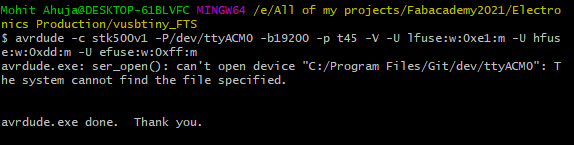
But this command did not work for me as visible in the above screenshot. So I decided to do two things, I decided to change the makefile and the programmer section in this command. I changed the programmer from stk500v1 to usbtiny in the makefile as seen below:
I also modified the code to be the following:
This seemed to do the trick. But the job was not done. The next step was to flash the board and this was done by running:
After this, the next step was to burn the reset fuse, and this was done by running:
After this, the ISP was ready to use, and I proceeded to disconnect the board from the ISP and connected it directly to the Computer to see if it got recognised or not. To my absolute delight, it did, as seen below:
So now I am the happy owner of three different FabISPs.
Alex's ISP
Brian's ISP