
Electronics Production:
Objective:
1. Group assignment:
This week is having the following Objectives for the Group-
Characterize the design rules for your PCB production process: document feeds, speeds, plunge rate, depth of cut (traces and outline) and tooling. ✔
document your work (in a group or individually)✔
2. Individual assignment:
• Make an in-circuit programmer by milling and stuffing the PCB, test it, then optionally try other PCB fabrication process.
Learning Outcomes:
• Described the process of milling, stuffing, de-bugging and programming
• Demonstrate correct workflows and identify areas for improvement if required
Checklist:
• Linked to the group assignment page
• Documented how you made (mill, stuff, solder) the board
• Documented that your board is functional
• Explained any problems and how you fixed them
• Included a ‘hero shot’ of your board
Opening Quotes:
• Electronics is clearly the winner of the day.--- John Ford
• When I was a teenager in the late 30's and early 40's, electronics wasn't a word. You were interested in radio if you were interested in electronics. --- Ken Olsen
• My hardcover sales are 17% down in books but up 400% in electronics. --- Lisa See
• By the end of this decade, computers will disappear as distinct physical objects, with displays built in our eyeglasses, and electronics woven in our clothing, providing full-immersion visual virtual reality.--- Ray Kurzweil
• Each of us is now electronically connected to the globe, and yet we feel utterly alone.---Dan Brown
Electronics Production:
The task of this week included assignments to be done in group and individually. We have to mill PCB plates, solder the components over it. For two weeks, we have been only working on the laptops. From last week, we have been making our hands dirty on the machines and learning to fabricate with the CNC machines.
Group Assignment:
For the Group assignment, we had to Characterize the design rules for our PCB production process: document feeds, speeds, plunge rate, depth of cut (traces and outline) and tooling.
document our work (in a group or individually)
Two of us already had experience of Milling and Soldering. They took lead and we divided the tasks amonst us. I have drafted the Group Assignment by taking the Snapshots, Screenshots and documenting the process. The details of the Group assignment could be found here.
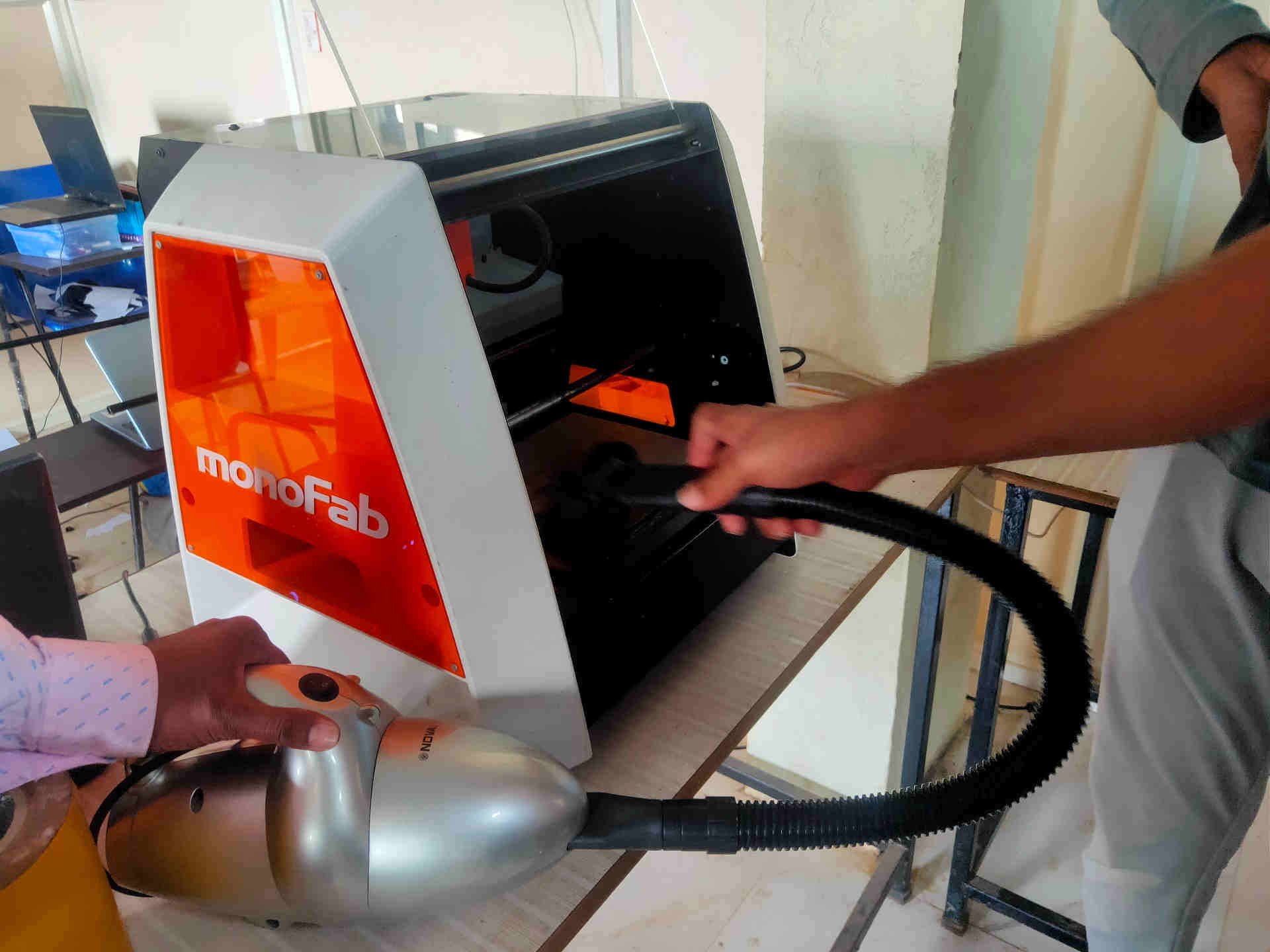
A. Introduction to PCB Milling machine at FabLab-0 – Vigyan Ashram, Pabal:
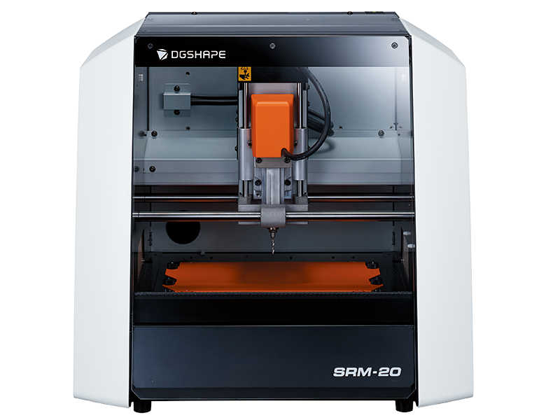
(Source: https://www.dgshape.com/en/srm-20/)
Introduction to Machine
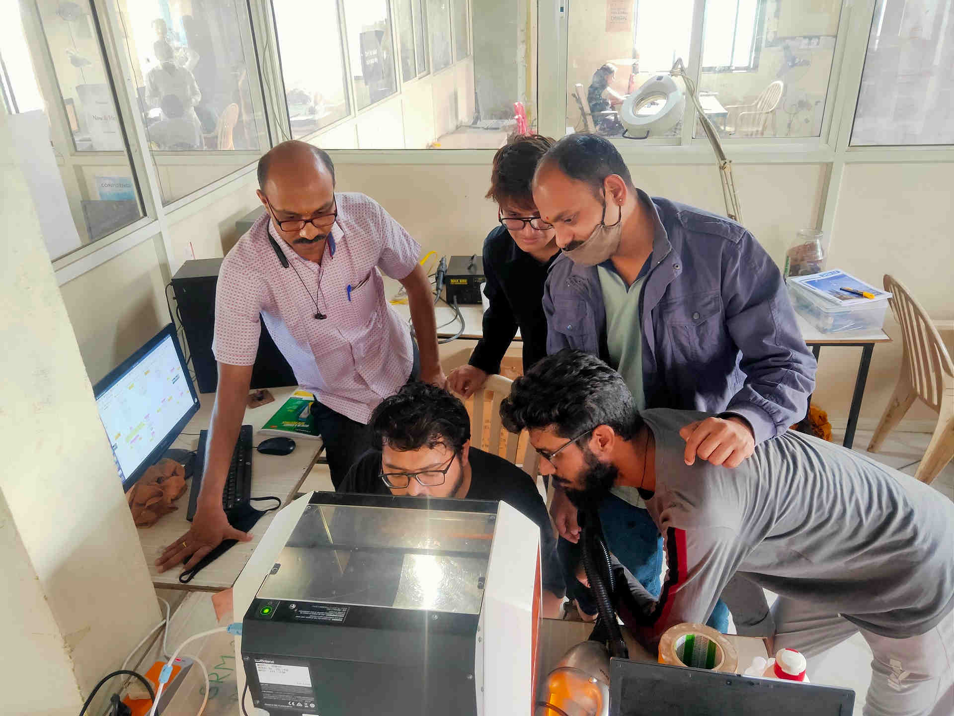
After the Global review, next day we were introduced to the milling machine.
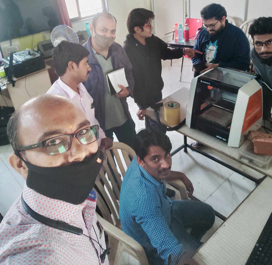
We have SRM-20 Milling Machine by DG Shape (Roland) in our FabLab. On Thursday, the 18th Fab. 2021 we were introduced to this machine by our Local Instructor (Mr. Suhas Labade). During the introduction, we were told about the DO’s and DON’T’s of the machine operation which included the Cleanliness of the machine and work area, ensuring safe and proper electrical connections. Door of the machine should be always closed while operating and giving commands or else it will not operate due to magnetic switch in the door for enhanced safety feature.
B. Preparing the SRM-20 machine for Milling:
PCB milling is the process of removing areas of copper from a sheet of printed circuit board material to recreate the pads, signal traces and structures according to patterns from a digital circuit board plan known as a layout file.
PCB milling is typically a non-chemical process and as such it can be completed in a typical office or lab environment without exposure to hazardous chemicals. High quality circuit boards can be produced using either process. In the case of PCB milling, the quality of a circuit board is chiefly determined by the system's true, or weighted, milling accuracy and control as well as the condition (sharpness, temper) of the milling bits and their respective feed/rotational speeds.(wikipedia)
Very first thing to start with the machine is to clean it and ensure proper electrical connections.
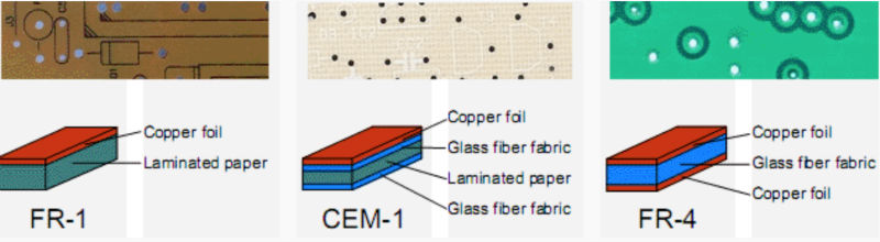
We have used the FR-1 material for PCB milling.
Our SRM-20 milling machine has used two layers of 12 mm acrylic sheets as sacrificial layers. This is because the head of the machine cannot reach the depth of the bed.
Steps followed by us for the operation of the Milling machine are as follows:
- 1. Unmounting the previously mounted PCB plate if any by using a Spatula.
- 2. Cleaning the sacrificial layer by acetone
- 3. Ensure complete removal of the adhesive tape from the bed.
- 4. Use Vacuum cleaner to clean any residues.
- 5. Select and use an already cut piece of the PCB plate (FR-1) Size: about 4 x 6 in.
- 6. Clean the PCB plate and remove any dust or sticky material over it
- 7. Ensure that the plate is completely horizontal.
- 8. Remove the bubbles if any by sliding another plate over it.
- 9. Remove the cover of the adhesive tape.
- 10. Properly mount the PCB plate on the bed of the machine.
- 11. Press gently for proper adhesion (or else the PCB plate will pop up after the cut or may even have burring and improper trace cut.)
- 12. Use the levelling the gadget to ensure horizontal surface. *(We have used the already mounted plate for the test cut of the group assignment)
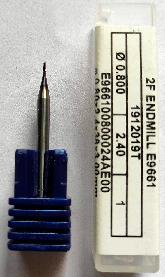
- 13. Once the plate is firmly set-in position, we then moved on to mount the drill bit.
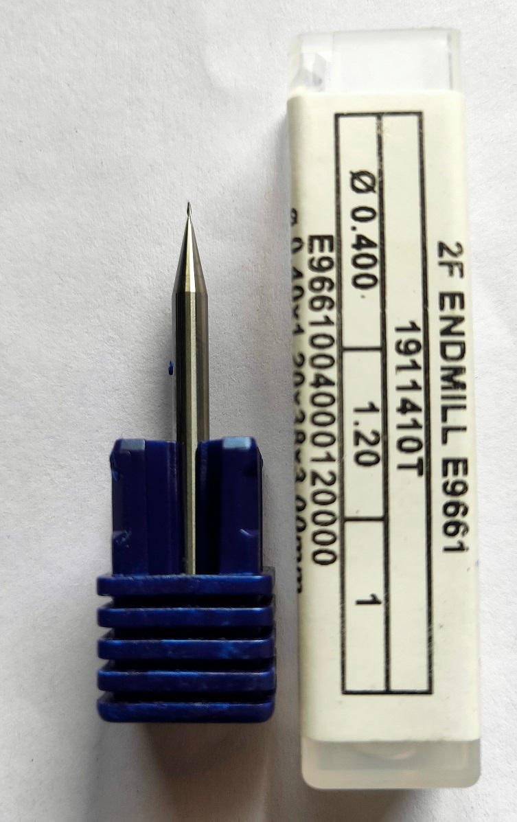
- 14. We have used the 1/64 drill bit for the trace cut of the PCB plate.
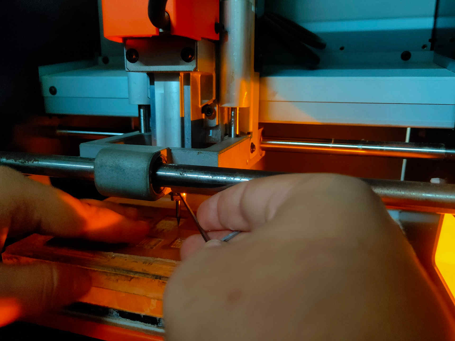
15. The process of setting / mounting the drill bit is as follows:
- i. Bring the header and the bed area in centre by giving command from the mods so that it is accessible.
- ii. Loosen the chuck using the L-N key by turning it in the anticlock wise direction.
- iii. Insert the 1/64 drill bit in the chuck by one hand and tighten the chuck using L-N key by other hand. *(There are two holes; one is where the L-N key fits properly and simply rotates in the other hole.) *(Do not apply too much pressure on the L-N key; it is programmed to automatically lock itself even if gently forced.)
- iv. Set the z- axis to a height of 7-10 mm above the bed.
- v. Loosen the chuck and let the drill bit to descend down by gravity.
- vi. Tighten the chuck by using L-N key and turning it in the clockwise direction.
- vii. Note down the coordinates of the origin.
- viii. Close the door of the machine.
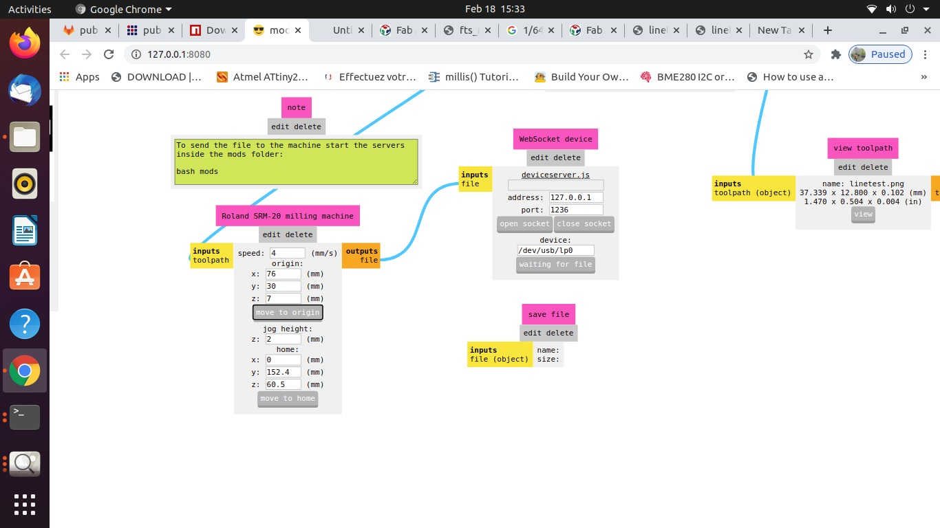
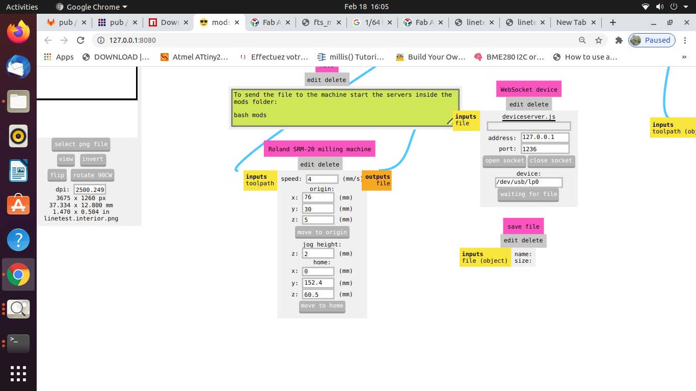
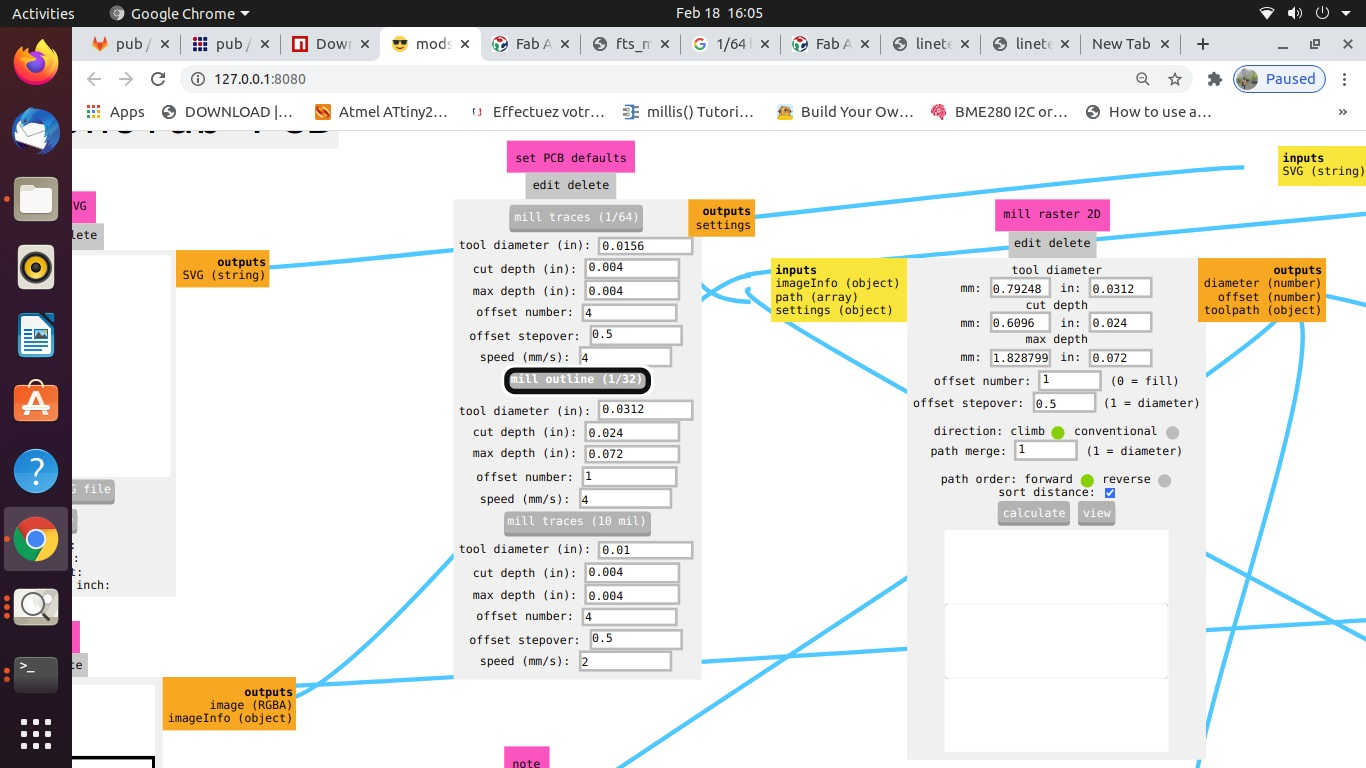
C. CAM Operation (Configuring / Generating Tool Path using MODS):
The process of CAM operation or Configuring / Generating Tool path is as follows:
- i. Download the two images of line test and line test interior from the fabacademy website.
(link1: http://academy.cba.mit.edu/classes/electronics_production/linetest.png)
(link2: http://academy.cba.mit.edu/classes/electronics_production/linetest.interior.png) - ii. The module was already installed in the desktop PC attached with the SRM-20 milling machine in our lab. You may learn, download and install it by following the process explained here. (link: https://gitlab.fabcloud.org/pub/project/mods)
- iii. The process of operating MODS is as:
- • Boot the Desktop terminal using Ubuntu OS.
- • Open Terminal and use commands --> cd Documents/mods
- • cd Documents to change directory --> mods --> bash mods
- • Again, Open New Terminal and use commands
- • cd Documents --> http – server
- • This will open a Window in Google Browser.
- • Right Click in the Window
- • Four options will be displayed like Modules, Programs, Edit, Options etc.
- • Select Programs --> Select Open --> Select SRM-20 Mill -->
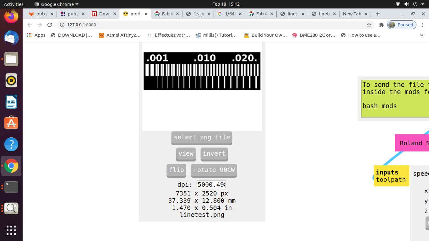
- • Go through each step of the Module -->Select the Photo/Image to be used for milling
- • Check the format of the image (.svg or .png)
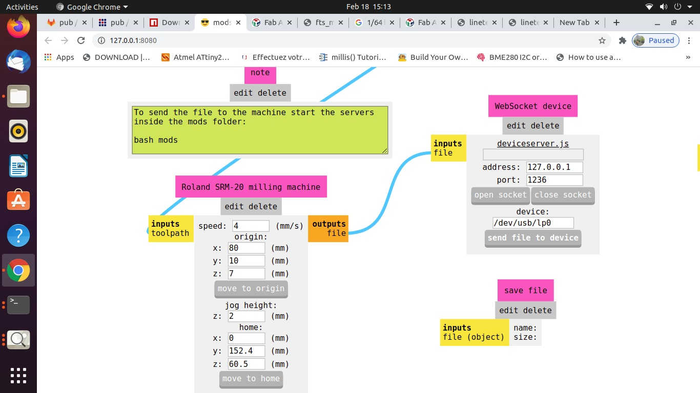
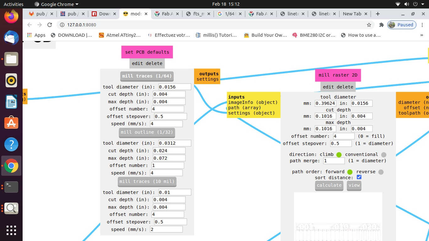
- • Check the selection of drill bit for Cut trace (1/64) or cut outline (1/32), Tool Path, Tool Diameter, Cut Depth, Offset, Stepovers, Speed and the position of the X, Y and Z axes. *(Always pay attention to the position of Z axis while setting the origin or moving to the home and coming back to the origin position.
- • Open the Socket to enable communication between the computer and the machine
- • Calculate the path
- • Send the File for milling.

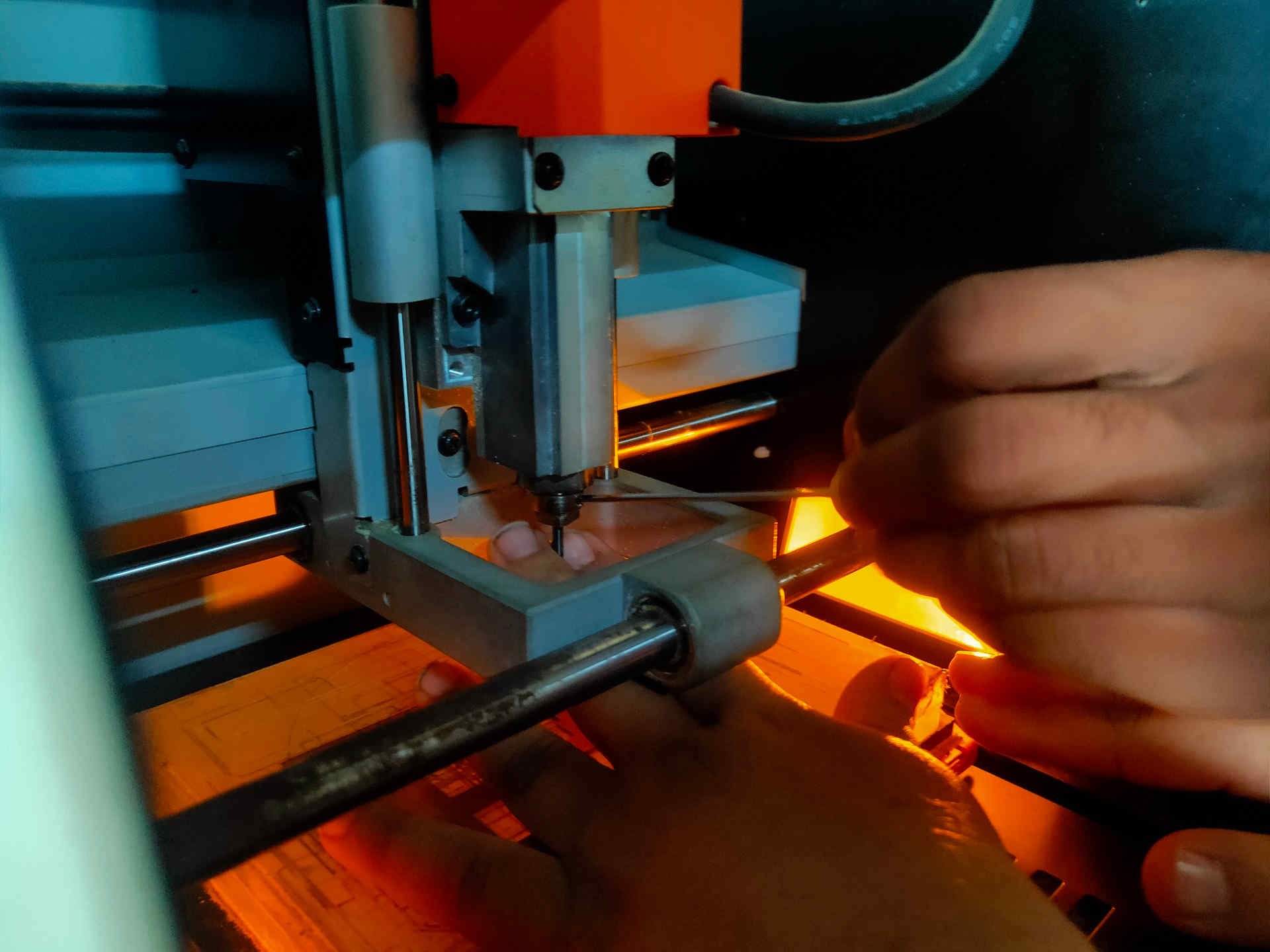
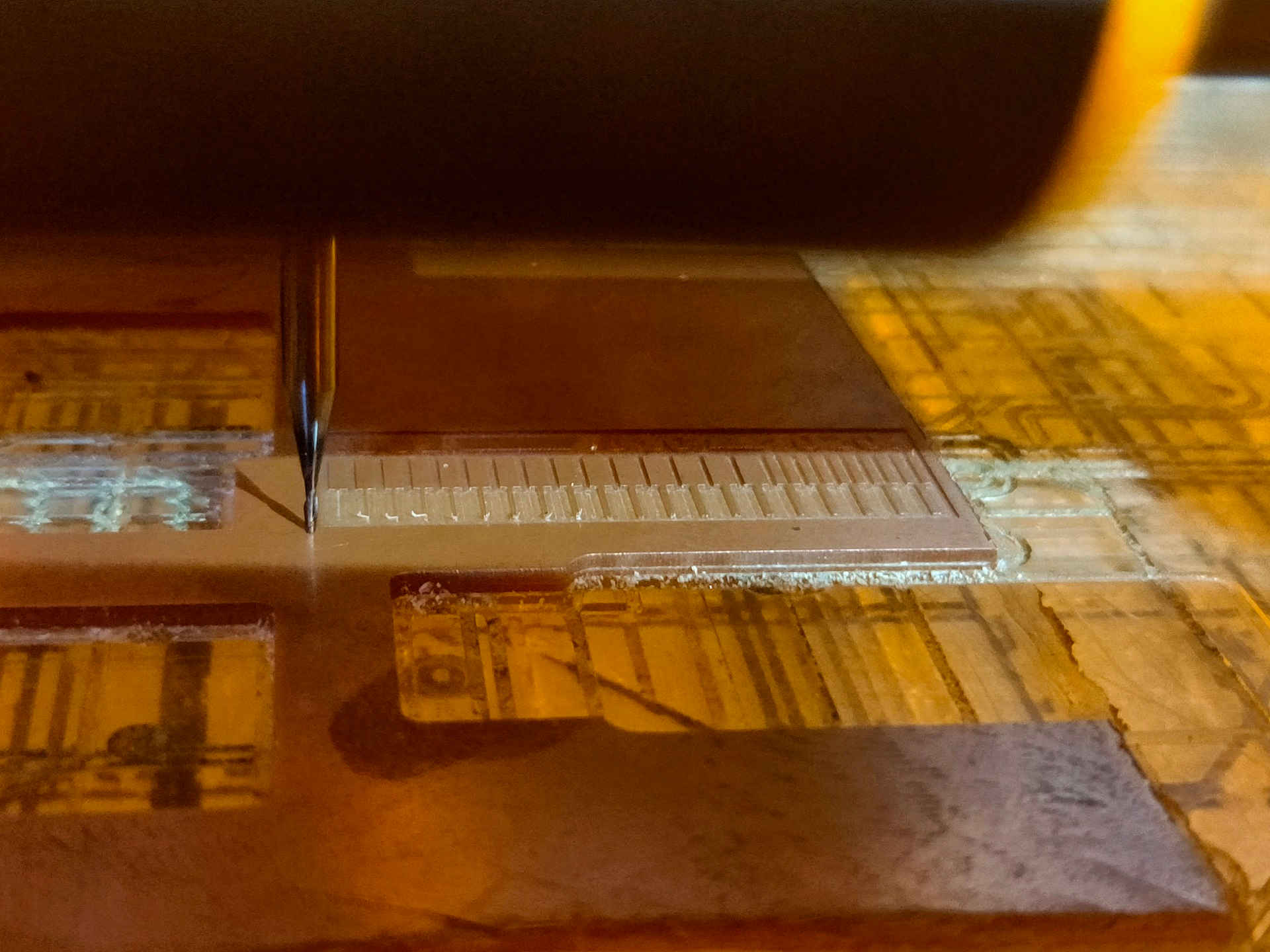
D. PCB Milling (Trace Cutting and Outline Cutting):
- i. Do not leave the machine unattended while the milling is going on.
- ii. After the completion of the trace image on the PCB plate, open the door of the machine.
- iii. Use vacuum cleaner to clean the residual particles. DO NOT try to clean the particles by blowing air through the mouth as these particles are hazardous and may cause illness.
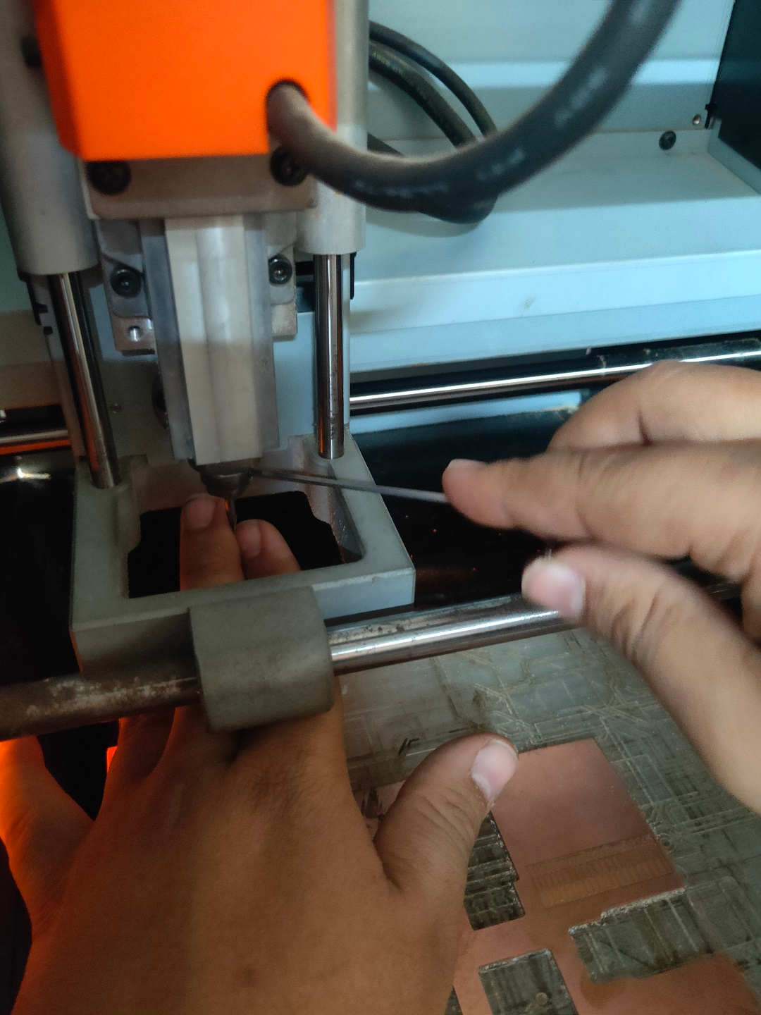
- iv. Check the plate for proper milling.
- v. If the plate is not properly milled, change (increase) the cut depth and give a double pass without changing the position of the plate and the drill.
- vi. Once, the plate is properly milled with cut trace, move the Z axis in upward direction, loosen the chuck using the L-N key and moving it in anticlock wise direction.
- vii. Unmount the 1/64 drill bit used for cut tracing.
- viii. Take 1/32 drill bit and mount it to the Chuck.
- ix. Properly tighten the drill bit and set the origin.
- x. Again, check the tool path using MODS and select the mill outline drill bit; check the Tool Diameter, Cut Depth, Offset, Stepovers, Speed and the position of the X, Y and Z axes.
- *(Always pay attention to the position of Z axis while setting the origin or moving to the home and coming back to the origin position.
- xi. Open the Socket to enable communication between the computer and the machine
- xii. Calculate the path
- xiii. Send the File for milling.
- xiv. After the milling of the cut outline is completed, use vacuum cleaner to clean the debris.
- xv. Collect the PCB plate.
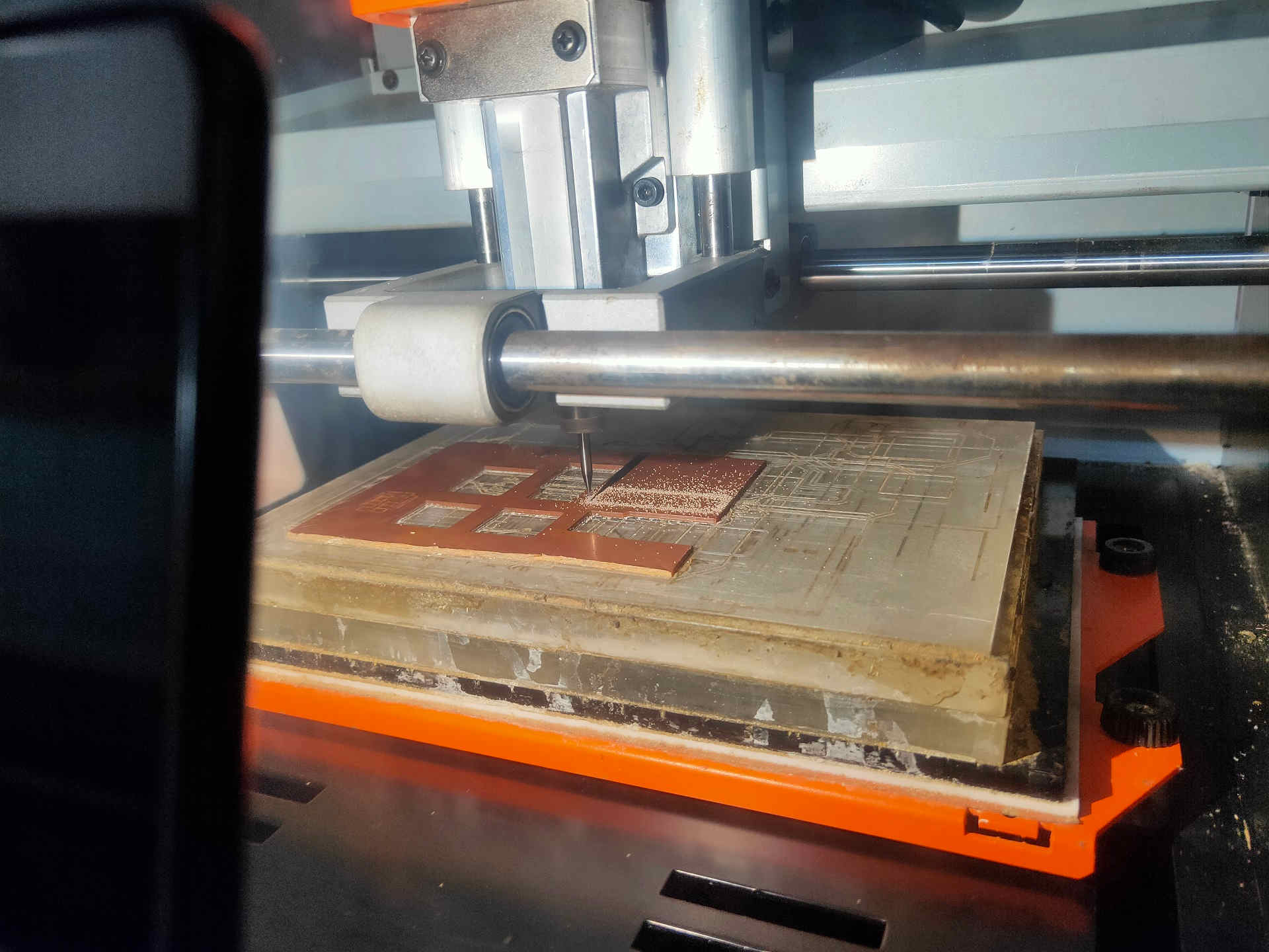
The PCB plate after milling cut trace.
Cut Outline milling about to start
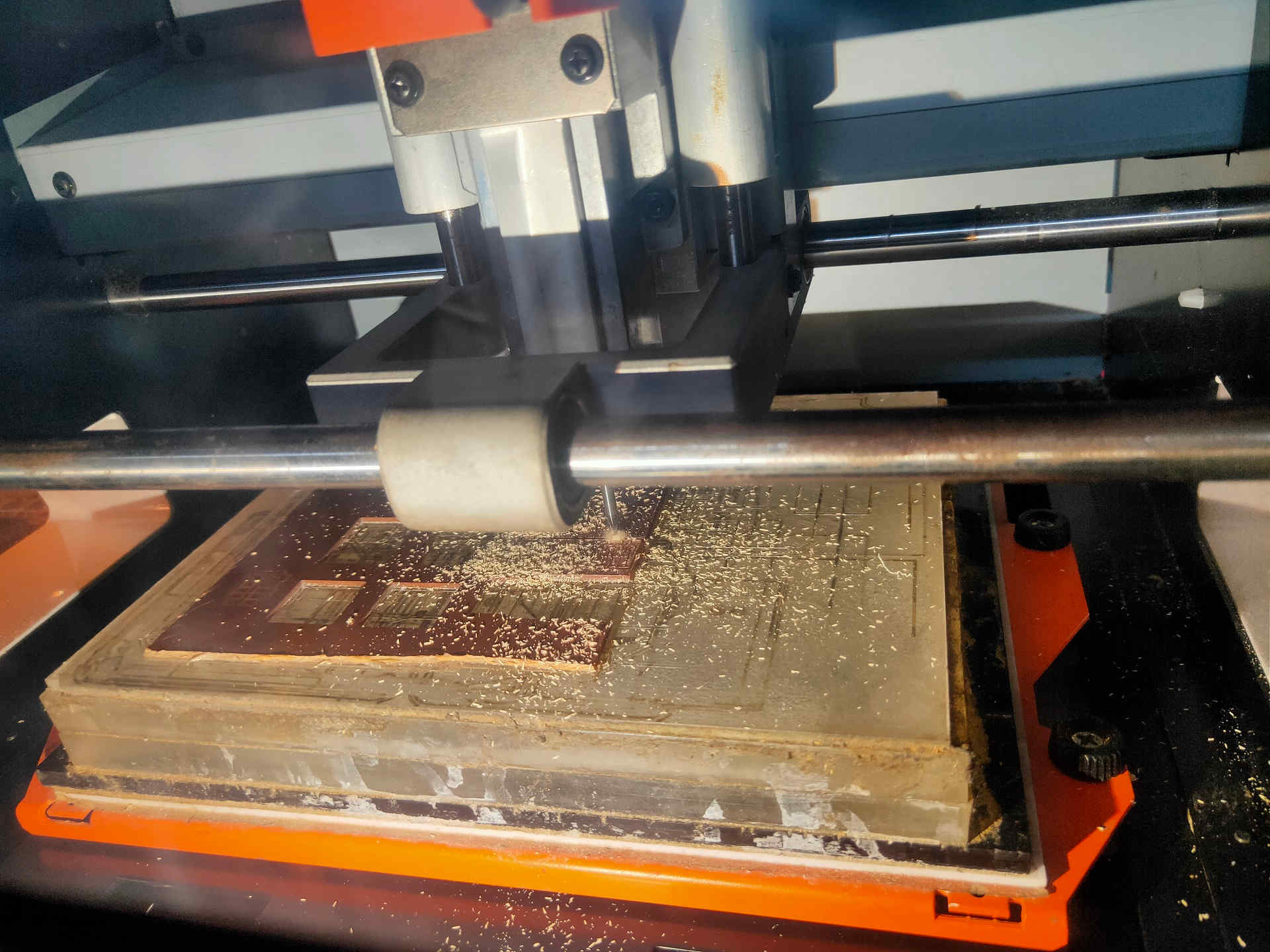
Cut Outline milling ongoing
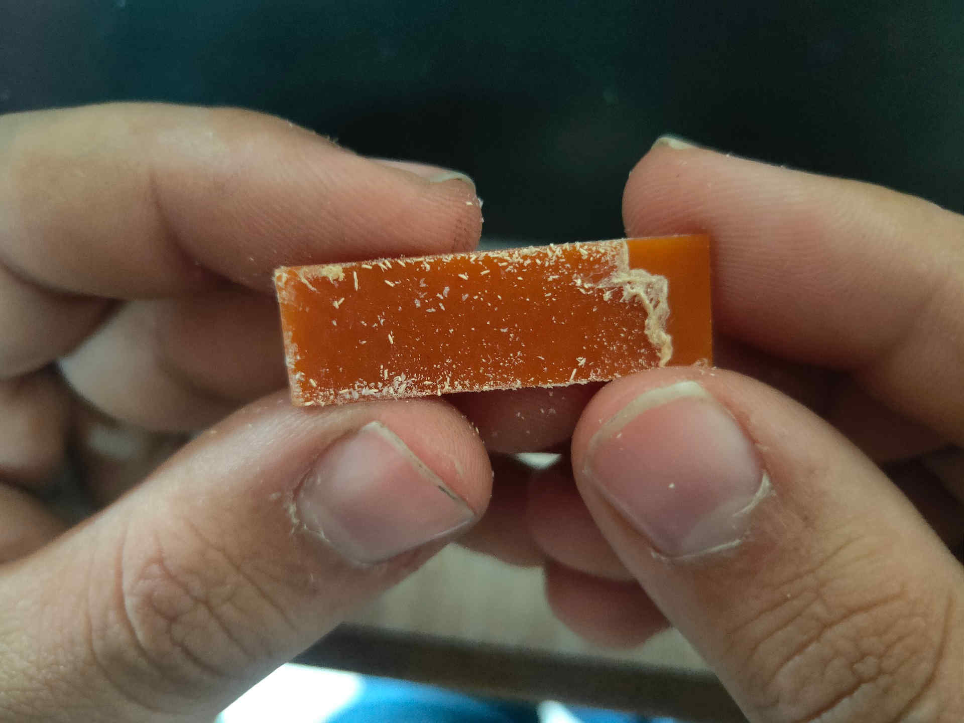
xvi. Clean the adhesive tape adhered to the base of the plate.
E. End Result:


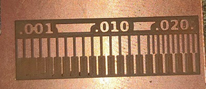
Trace Cut (Reference)
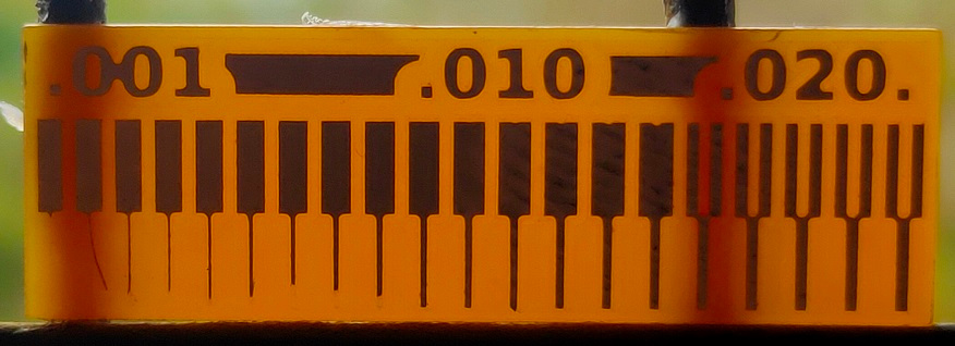
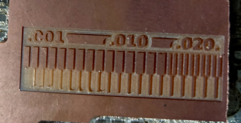
Trace Cut (Ours’ Group Assignment)
F. Learnings:
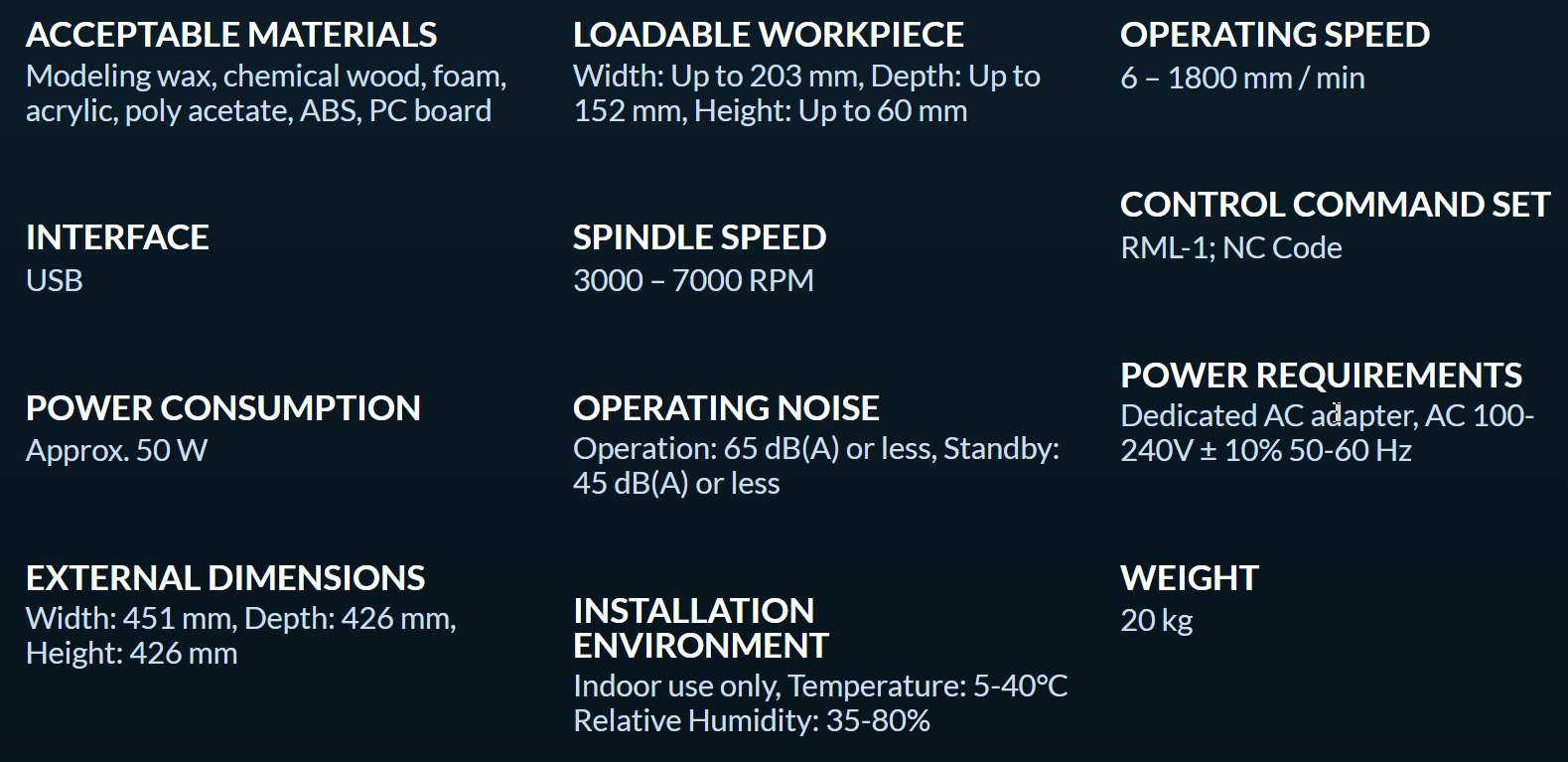
- i. Feeds:
- Tool Diameter for cut traces- 1/64 drill bit – 0.0156 mm
- Tool Diameter for cut outline- 1/32 drill bit – 0.0312 mm
- Image Size: 37.339 x 12.800 mm (7351 x 2520 px)
- ii. Speed: 4 mm/sec.
- iii. Depth of Cut: for Trace cut – 0.004 in.
- Outline cut – 0.6096 in (minimum)
- 1.8287 in (maximum)
- iv. Tooling:
- FR-1 PCB plates for milling
- L-N key for mounting and unmounting drill bits to chuck of the machine.
- Drill bit of 1/64 for mill trace cut
- Drill bit of 1/32 for mill outline cut
- Spatula for unmounting the PCB plate off the Overlay / sacrificial layer.
- Vacuum cleaner for cleaning
G. Observations / Findings / Conclusions:
These observations will be used in the Electronics Design week. These findings will help us to –
- - select proper tools like the size of the drill bit
- - set distance between the traces while PCB design
- - impact of the tool diameter on the trace width.
After comparing the Reference and our PCB trace milling, it is found that:
- - if we keep the distance between the two traces less than 0.0156 then the machine will not mill it.
- - The traces more than 0.004 are visible and will sustain later.
H. Caution:
- 1. Ensure Cleanliness and proper electrical connections of the machine.
- 2. Do not blow the air by mouth to clean the residues of the milling. Use vacuum cleaner.
- 3. Always carefully handle the drill bits as they may break if mishandled.
- 4. Check the position of the Z axis before moving to Home or Origin position.
- 5. Ensure the completely horizontal position of the plate after mounting on the bed.