Mohit Ahuja's Fabacademy 2021
Electronics Design
Group Assignment
This is the link to the group project for this week, where we checked the microcontroller circuit's properties using different test equipment:
Group Project
Individual Assignment
Using Kicad
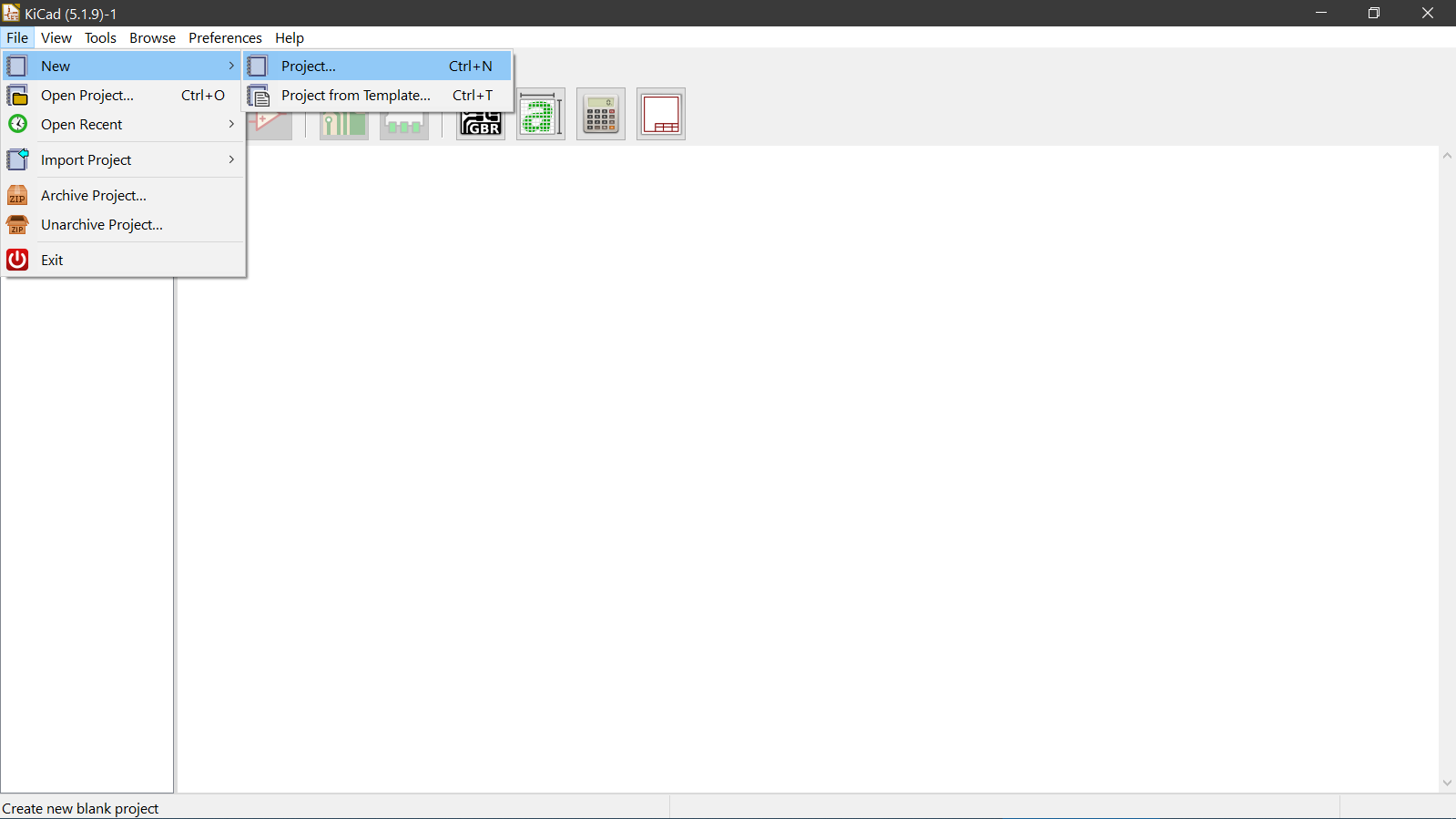
Starting a new project by going to File>New>Project
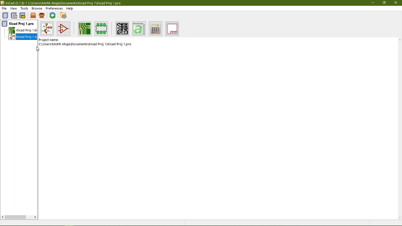
After entering the name of the project, this is the screen that I see:
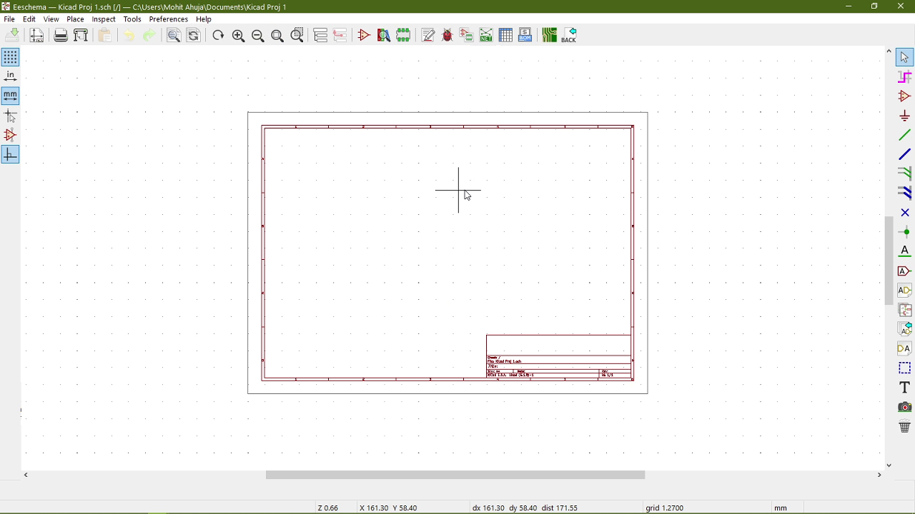
I opened the schematic file which is the file with the .sch extension and this screen popped up:
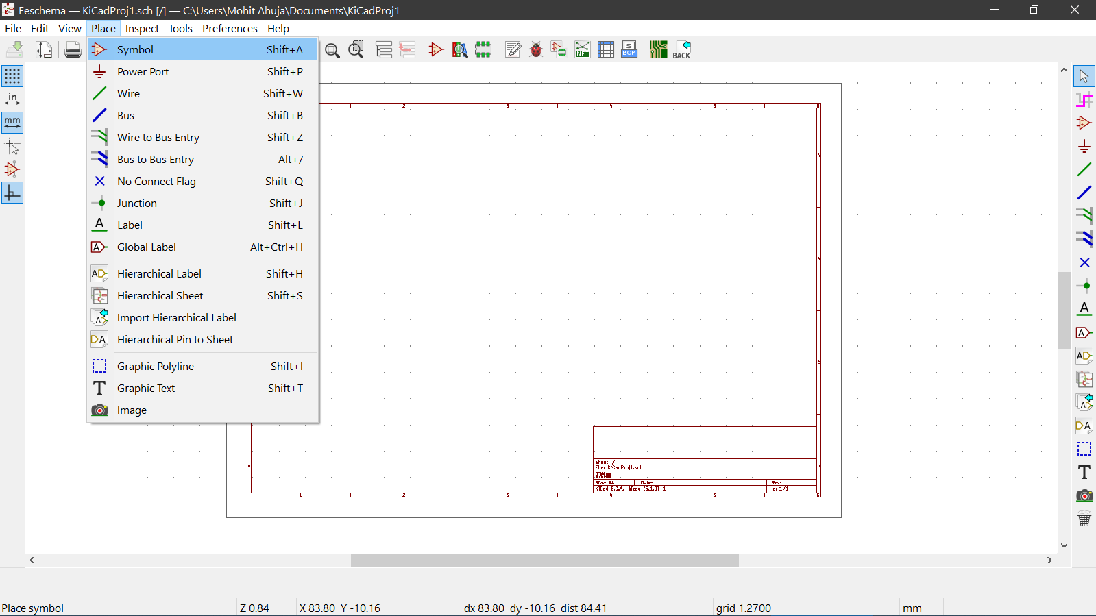
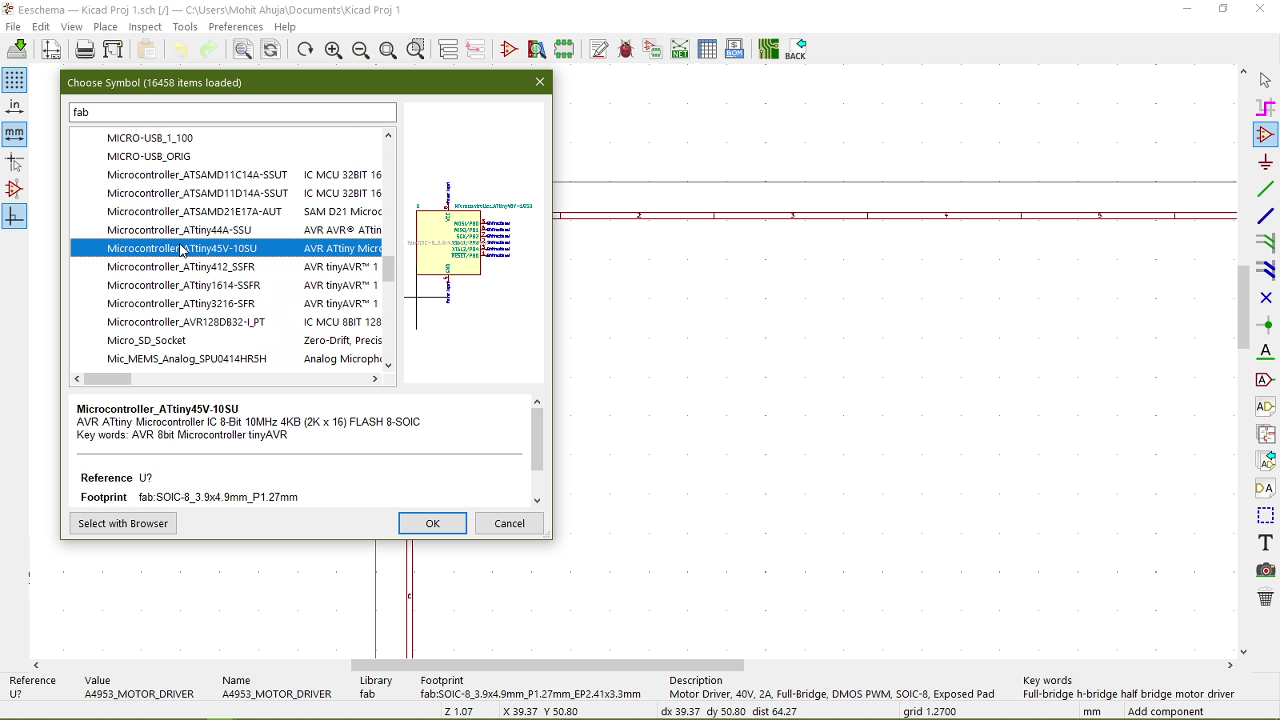
I then places the components using the Place>Symbol menu.
I selected the appropriate components one by one from the fab library of components
Then I started assigning labels to all the pins based on how I want to connect the components. I did that by going to Place>Global Label
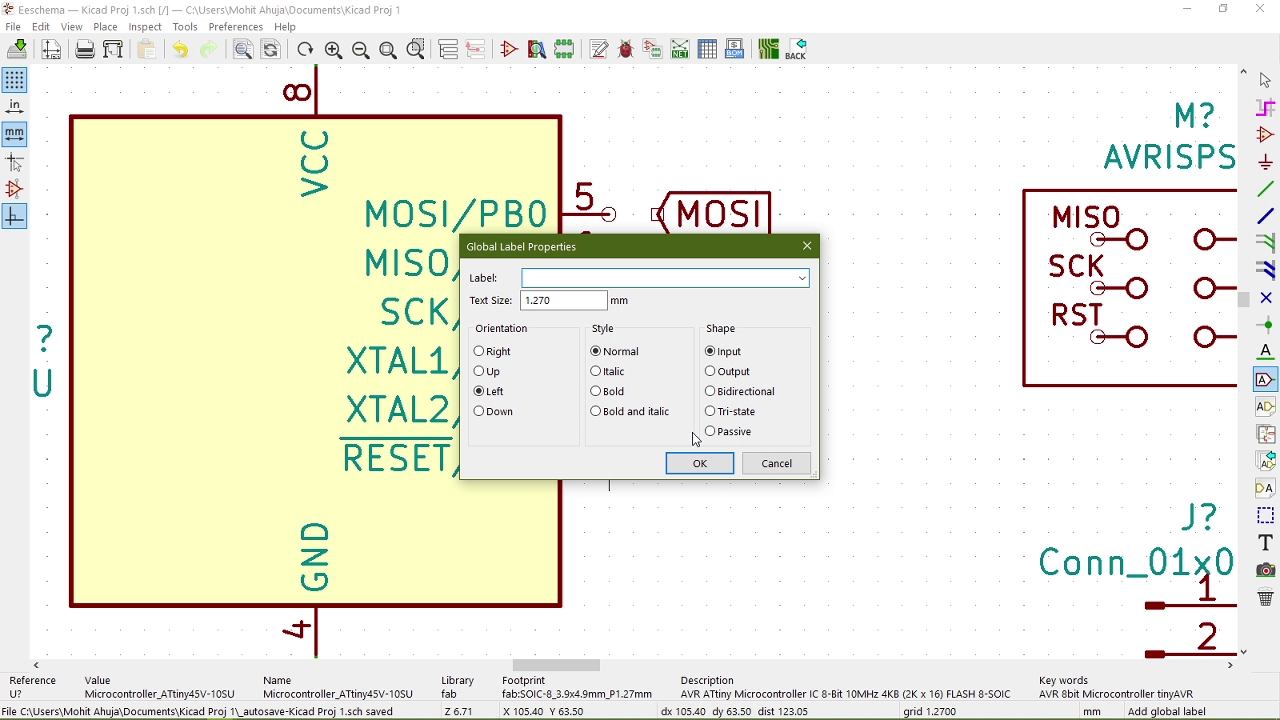
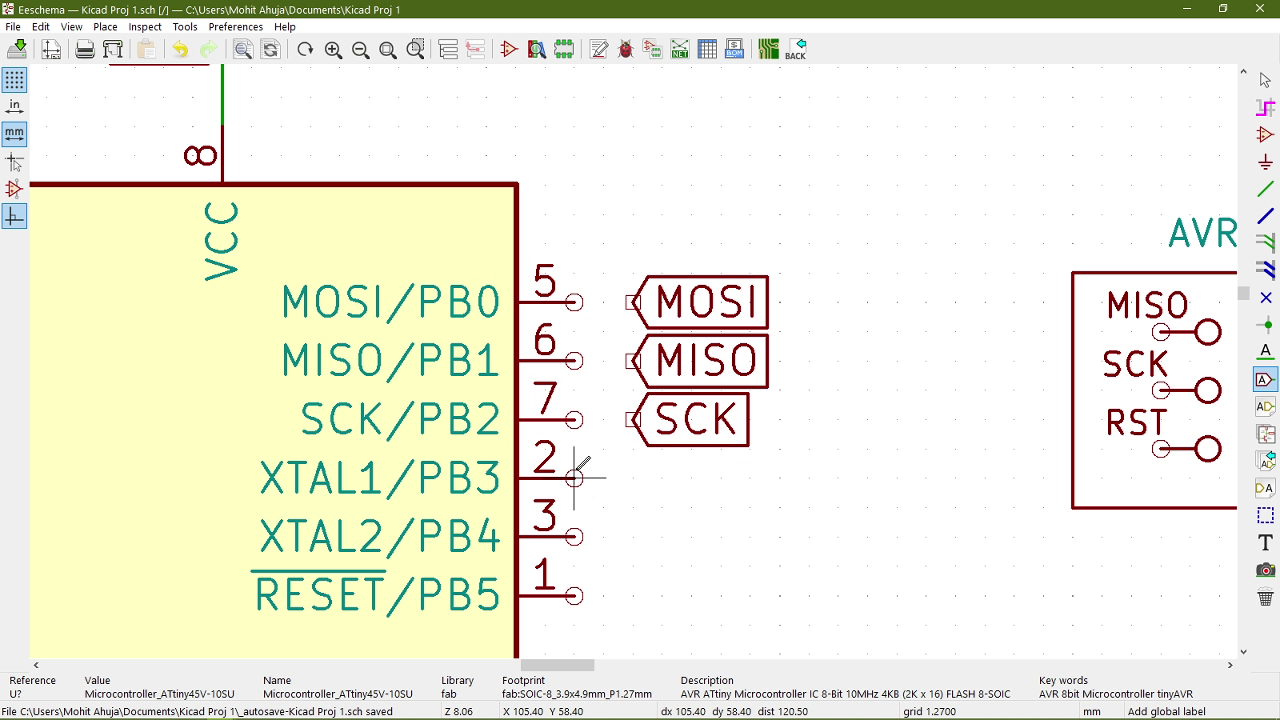
This is what it looked like after the labels were added:
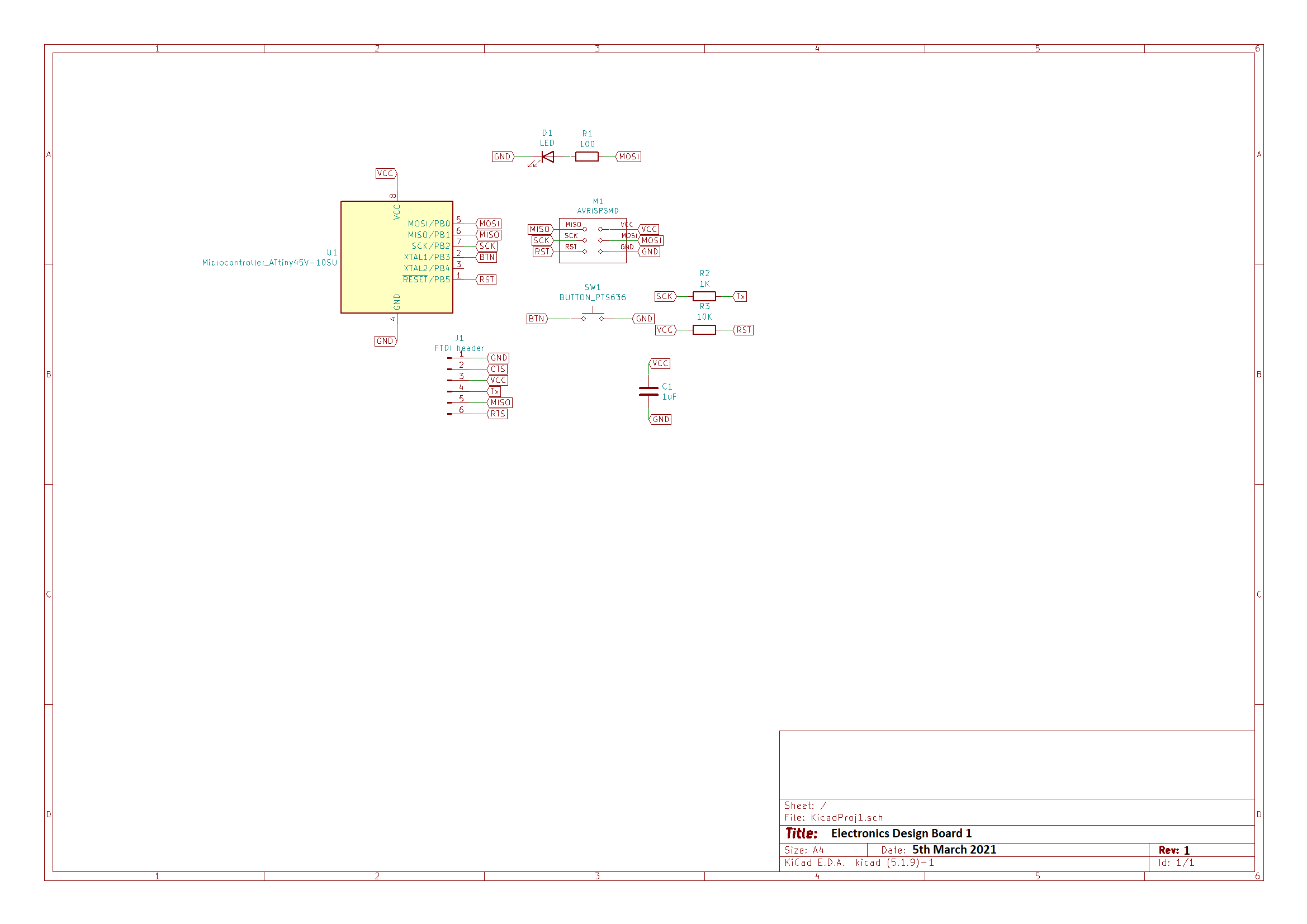
Then I connected everything appropriately, taking reference from Neil's Hello Echo World Board. This is the schematic after adding the LED and the button as required by the assignment:
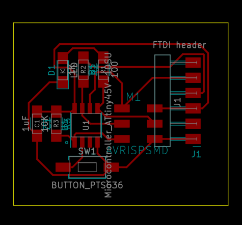
Designing the Traces
I first arranged the components in the configuration I wanted.
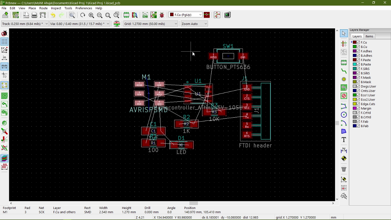
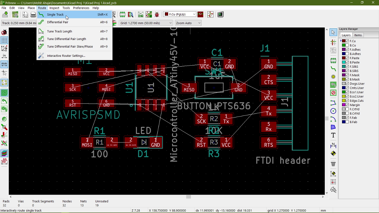
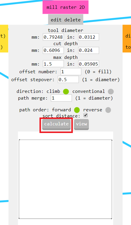
Then I started putting the traces down by using:
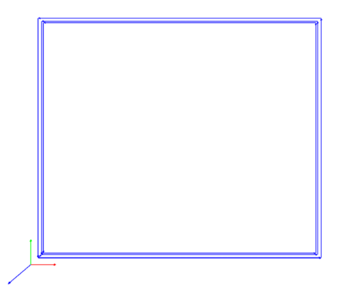
Then I made the outline of the board using:
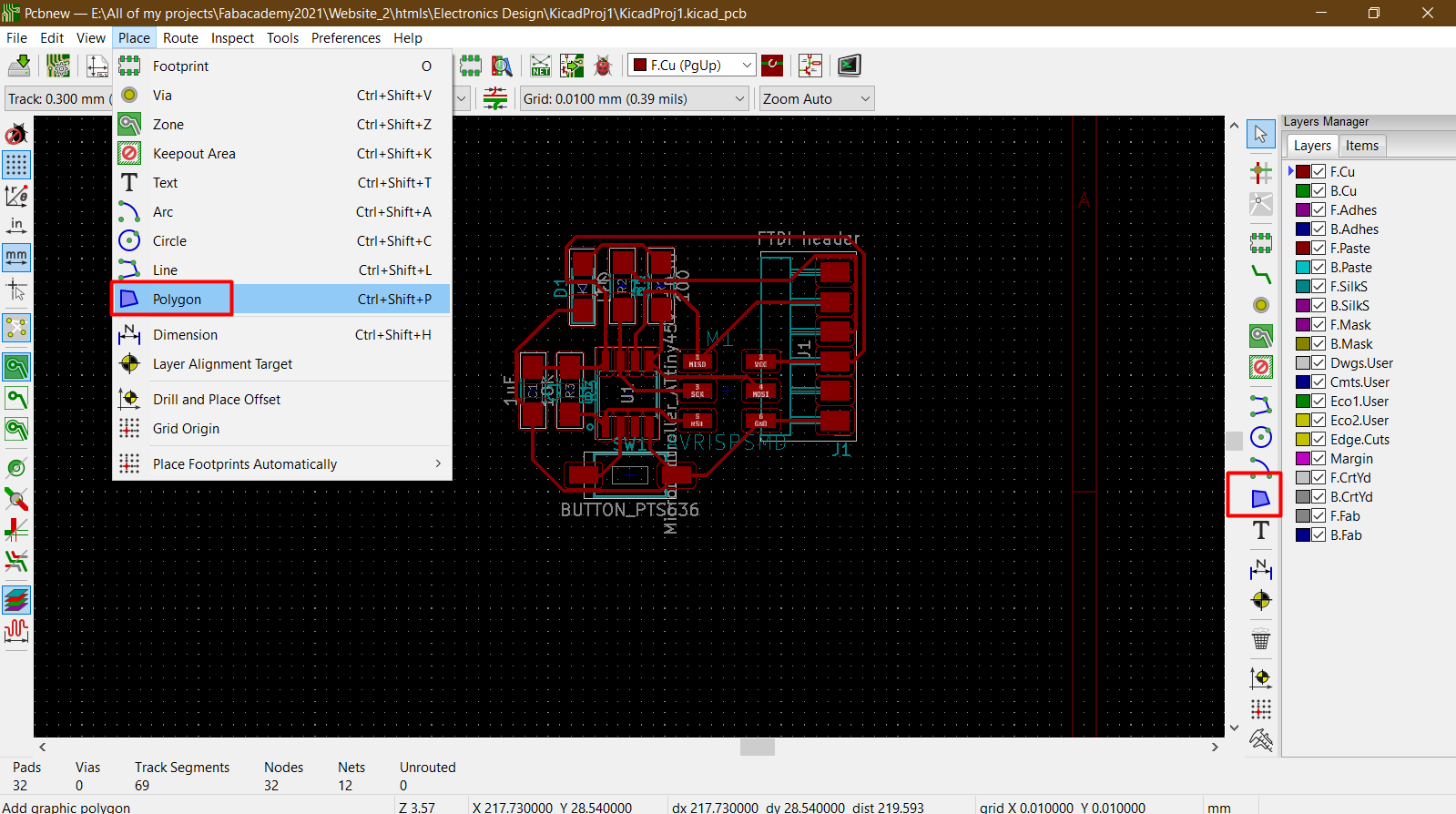
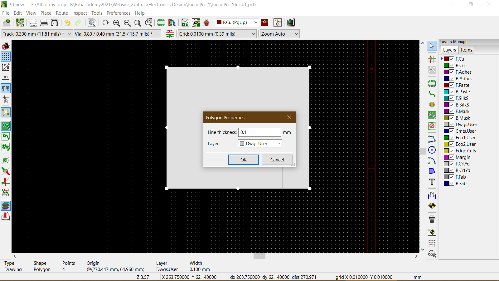
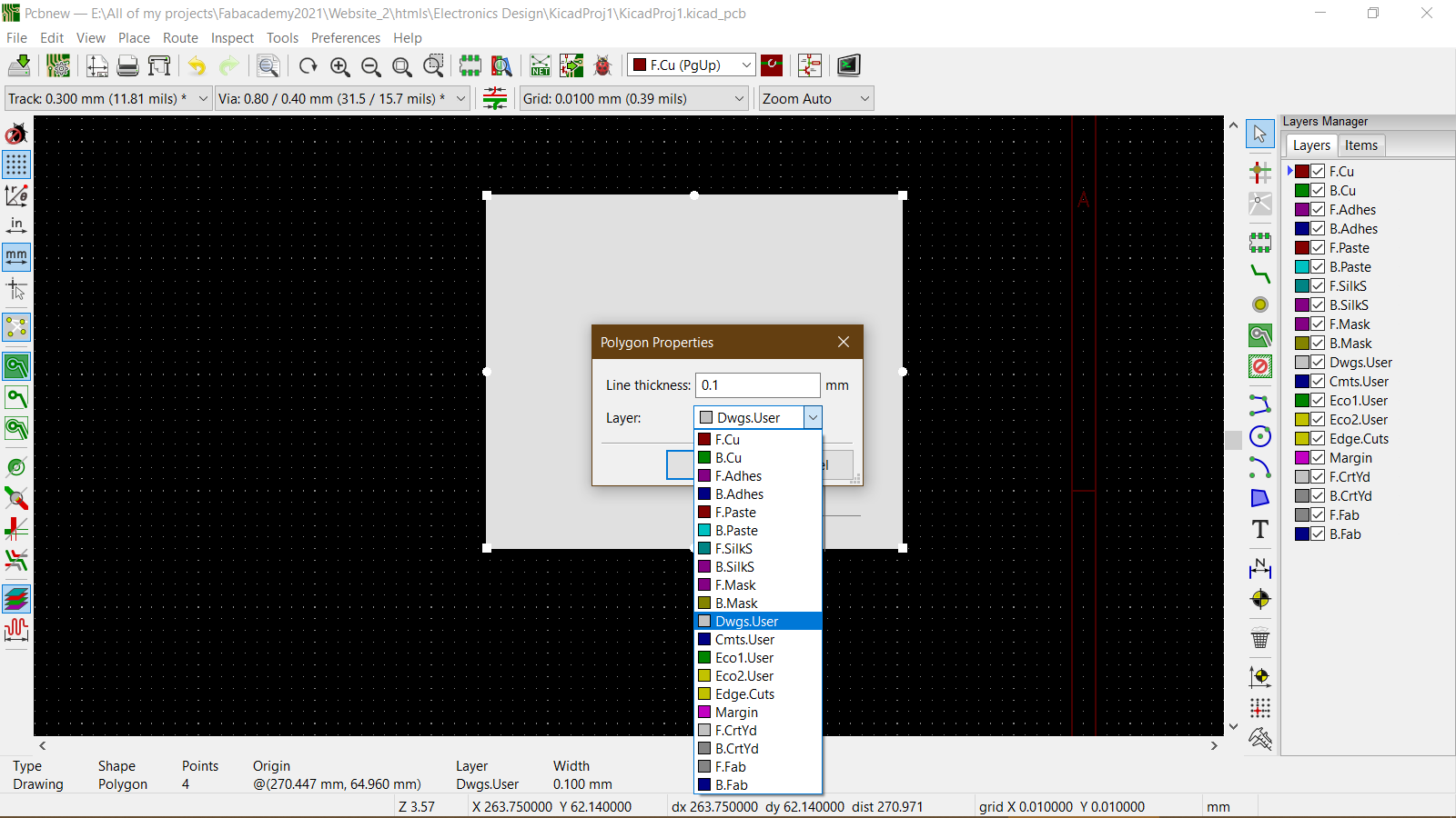
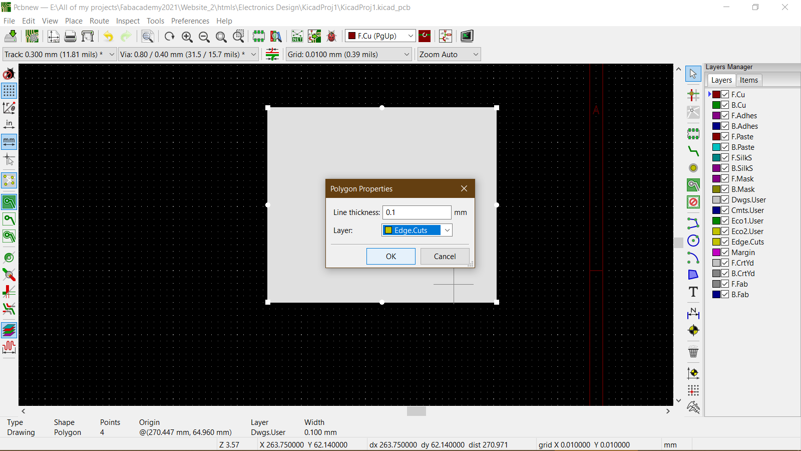
I changed the outline layer by double clicking on the polygon and then changing the layer:
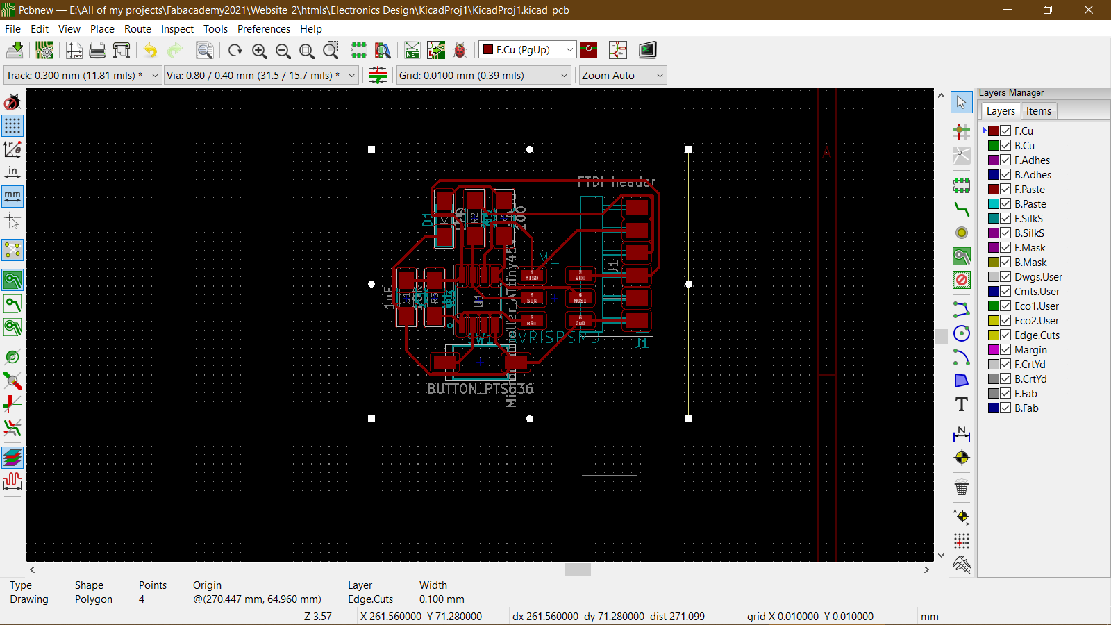
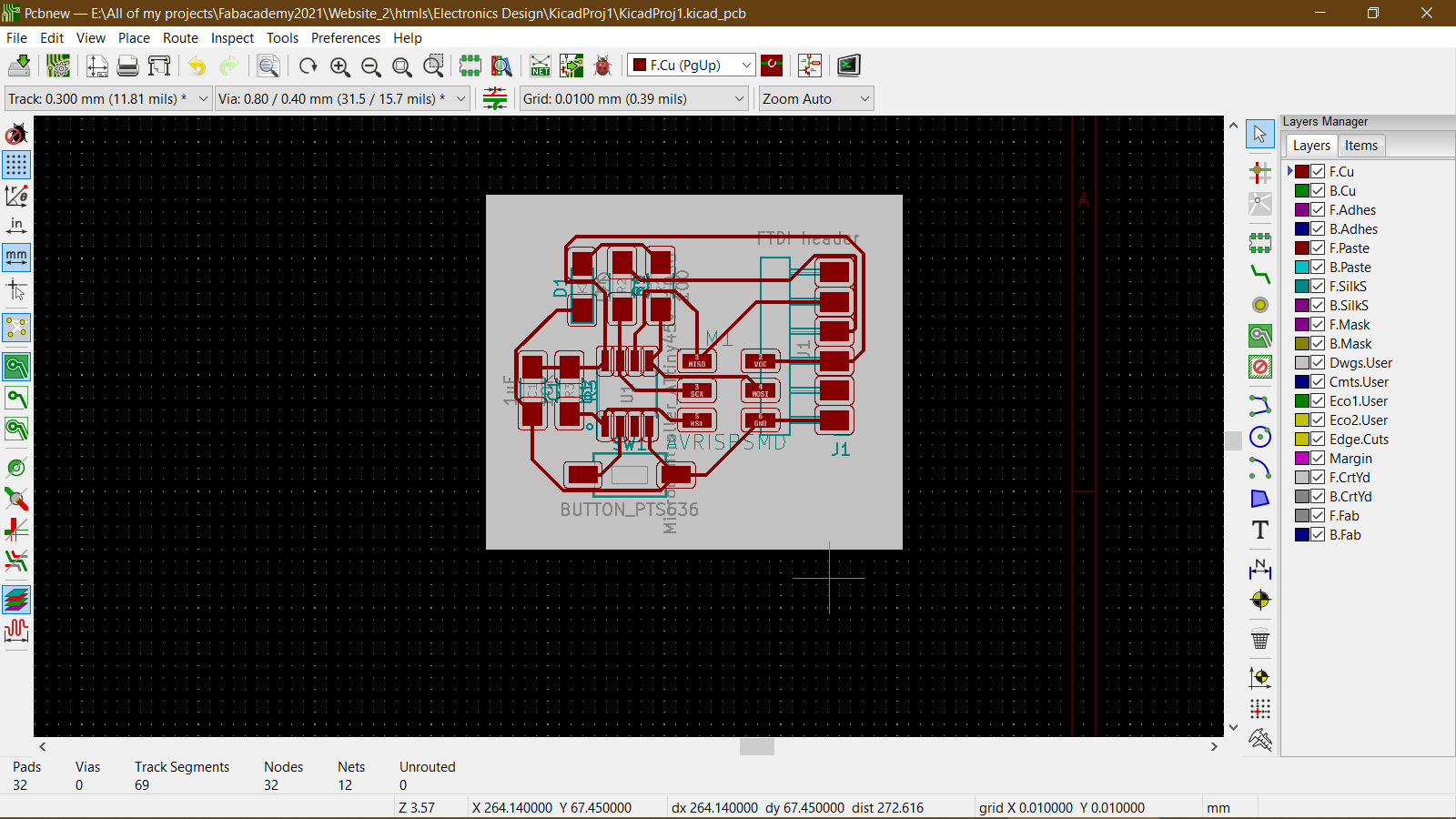
This was the final PCB design.
Kicad Project files

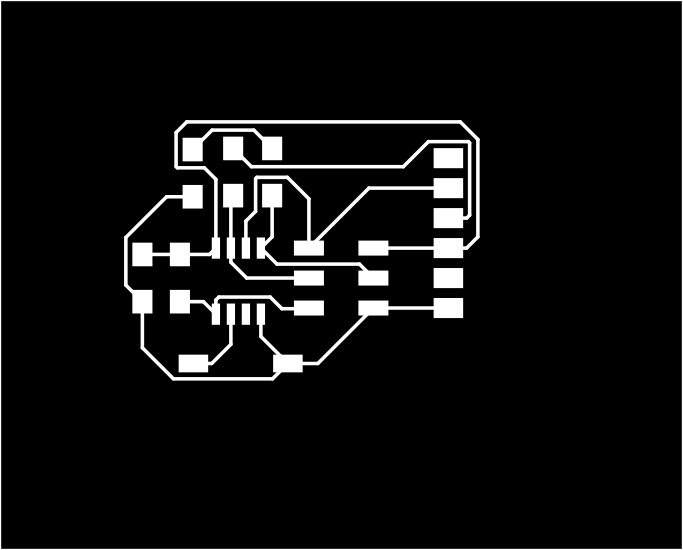
SVG Traces File for the PCB
SVG Cutout File for the PCB
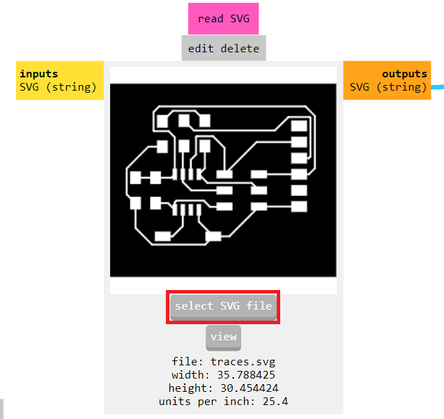
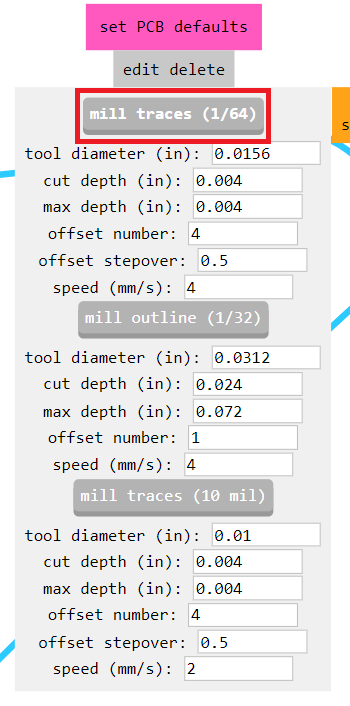
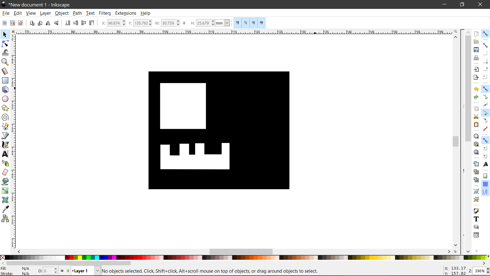
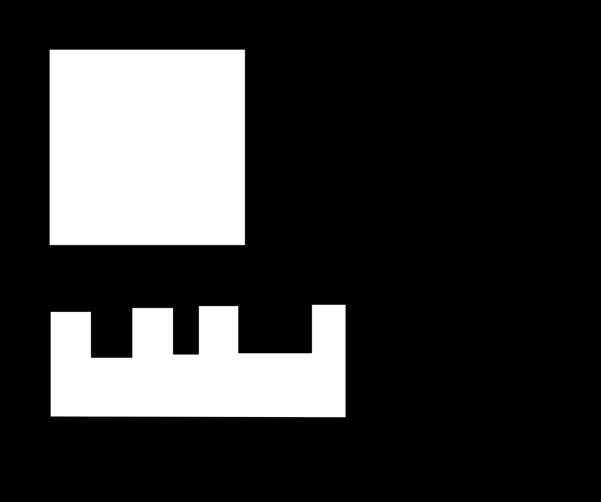
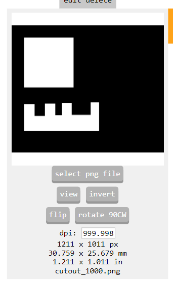
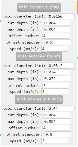
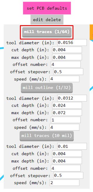
Milling the circuit using mods
Traces
Cutout
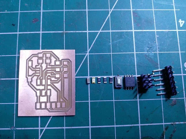
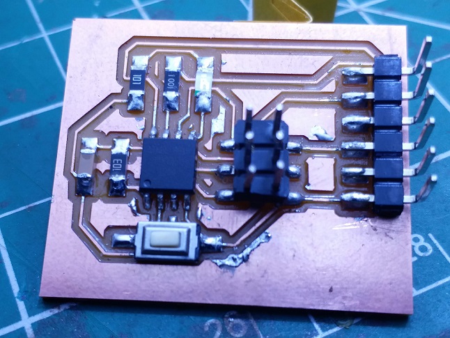
Soldering
Programming:
Blink Sketch
/*
  Blink

  Turns an LED on for one second, then off for one second, repeatedly.

  Most Arduinos have an on-board LED you can control. On the UNO, MEGA and ZERO
  it is attached to digital pin 13, on MKR1000 on pin 6. LED_BUILTIN is set to
  the correct LED pin independent of which board is used.
  If you want to know what pin the on-board LED is connected to on your Arduino
  model, check the Technical Specs of your board at:
  https://www.arduino.cc/en/Main/Products

  modified 8 May 2014
  by Scott Fitzgerald
  modified 2 Sep 2016
  by Arturo Guadalupi
  modified 8 Sep 2016
  by Colby Newman

  This example code is in the public domain.

  http://www.arduino.cc/en/Tutorial/Blink
*/
int LED = 0;
int del = 1000;

// the setup function runs once when you press reset or power the board
void setup() {
  // initialize digital pin LED_BUILTIN as an output.
  pinMode(LED, OUTPUT);
}

// the loop function runs over and over again forever
void loop() {
    digitalWrite(LED, HIGH);   // turn the LED on (HIGH is the voltage level)
    delay(del);               // wait for a second
    digitalWrite(LED, LOW);    // turn the LED off by making the voltage LOW
    delay(del);               // wait for a second
}
Blink sketch file
Output:
Serial Communication using SoftwareSerial
/*
  Software serial multple serial test

  Receives from the hardware serial, sends to software serial.
  Receives from software serial, sends to hardware serial.

  The circuit:
   RX is digital pin 2 (connect to TX of other device)
   TX is digital pin 1 (connect to RX of other device)

  Note:
  Not all pins on the Mega and Mega 2560 support change interrupts,
  so only the following can be used for RX:
  10, 11, 12, 13, 50, 51, 52, 53, 62, 63, 64, 65, 66, 67, 68, 69

  Not all pins on the Leonardo and Micro support change interrupts,
  so only the following can be used for RX:
  8, 9, 10, 11, 14 (MISO), 15 (SCK), 16 (MOSI).

  created back in the mists of time
  modified 25 May 2012
  by Tom Igoe
  based on Mikal Hart's example

  This example code is in the public domain.

*/
#include <SoftwareSerial.h>
SoftwareSerial mySerial(2, 1); // RX, TX

void setup() {
  mySerial.begin(4800);
}

void loop() { // run over and over
  mySerial.println("Hello, world?");
}
Software Serial sketch file
Output
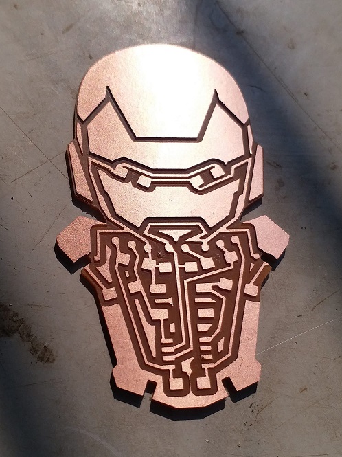
Making the Iron Man board.
References:
Ironman:https://twitter.com/adrianpontohart/status/786543326451294209/photo/1


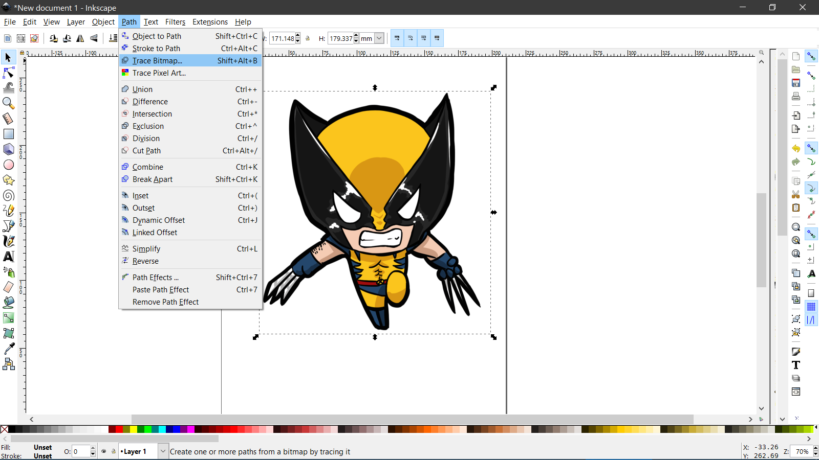
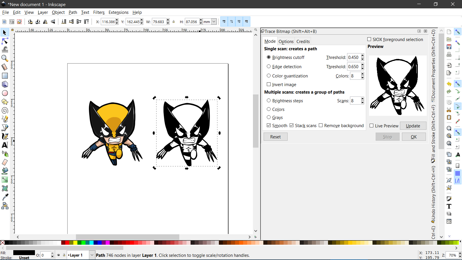
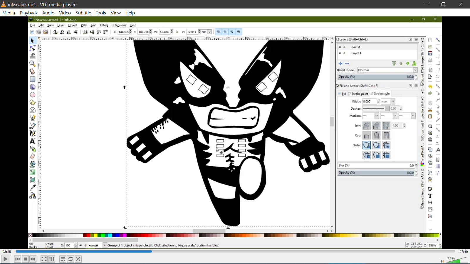
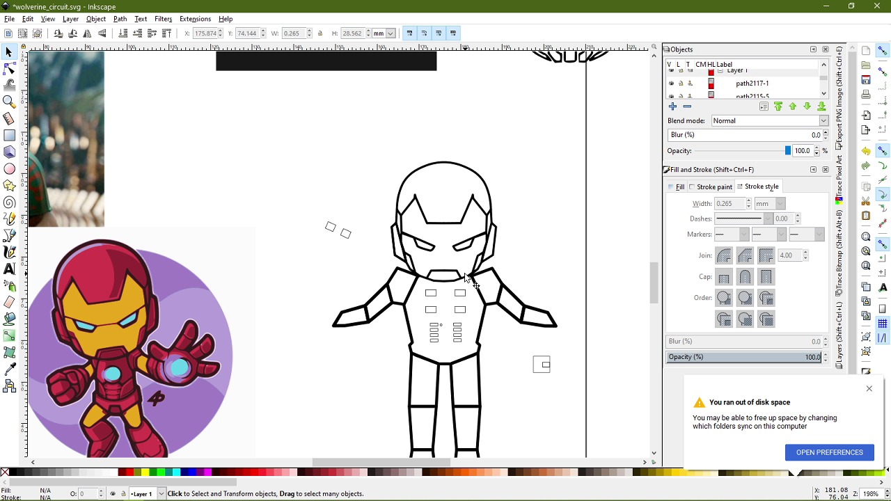
Using Inkscape
Tracing Bitmap
Initial Idea
Changing the idea to iron man with slotted parts due to inspiration from childhood toys found within cheetos packets:
Making Iron Man using the reference image linked previously:
Using Rhino to create a vector file.

Pinout of the board:
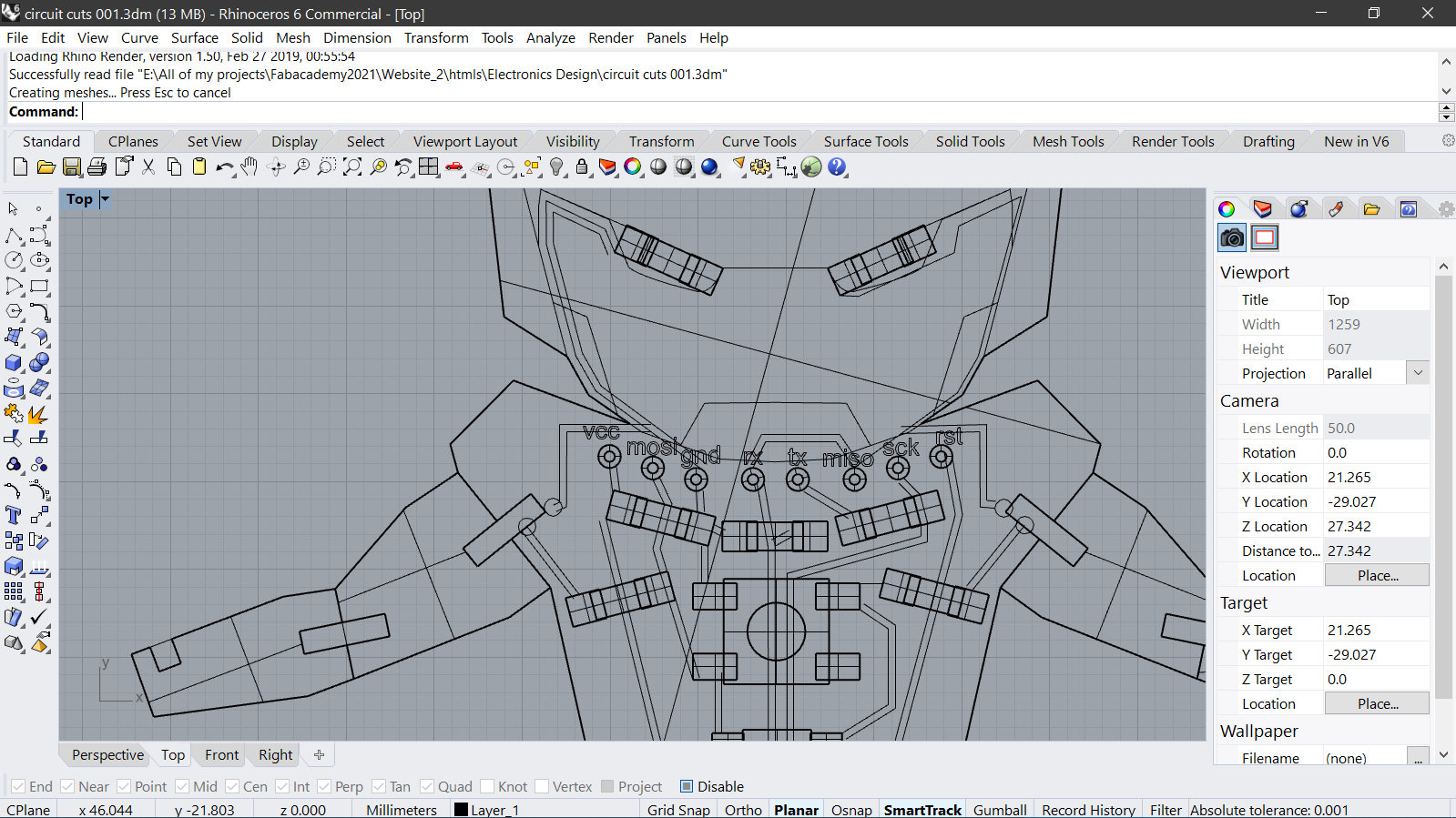
Original Rhino file of the Circuit
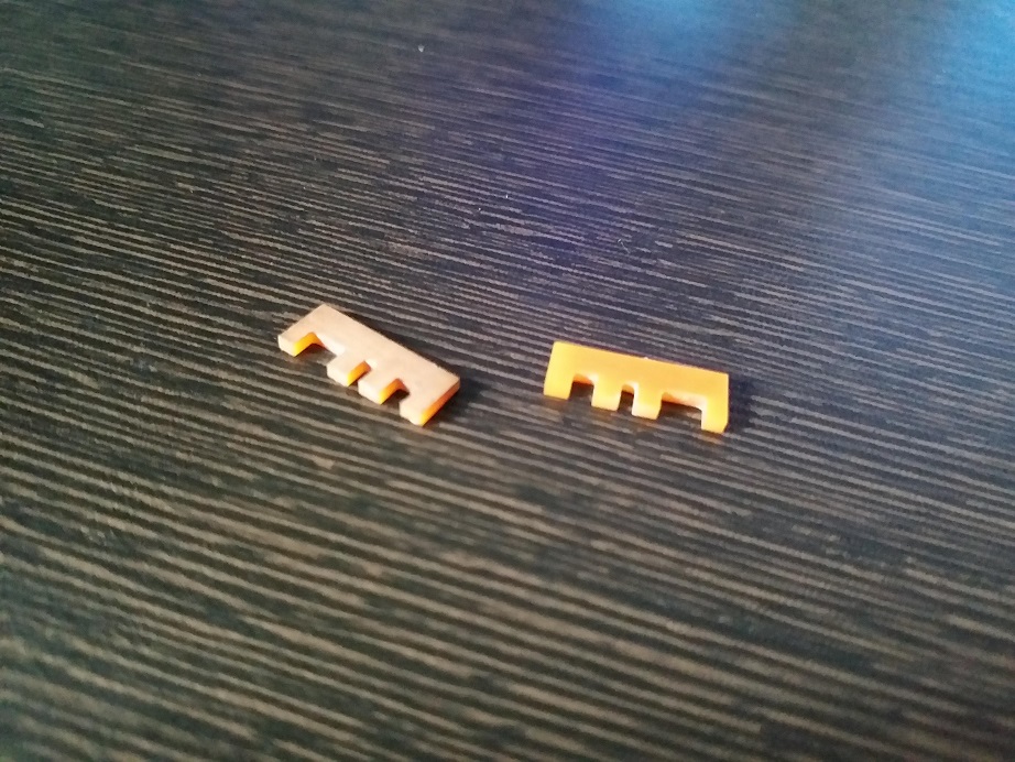
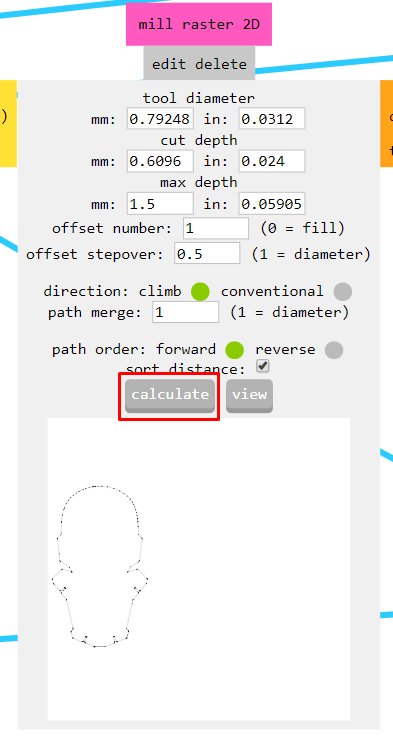
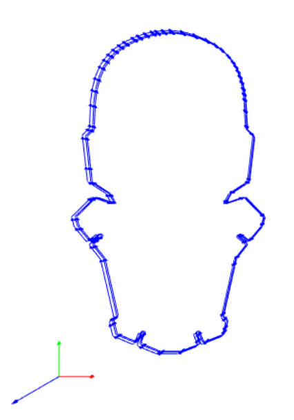
Designing parts to check the properties of the interlocking slots design.
Download the slot test file.
Milling:
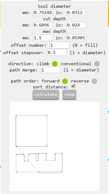
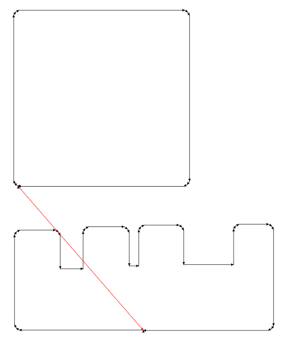
Result:
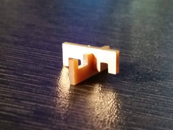
After I verified the width of slots needed to make the interlocking parts, I exported the outlines of the circuit from Rhino into PDF files and imported them into Inkscape:
PDF file of the torso
PDF file of the rest of the parts
After importing the PDF file, I created the files for the milling:
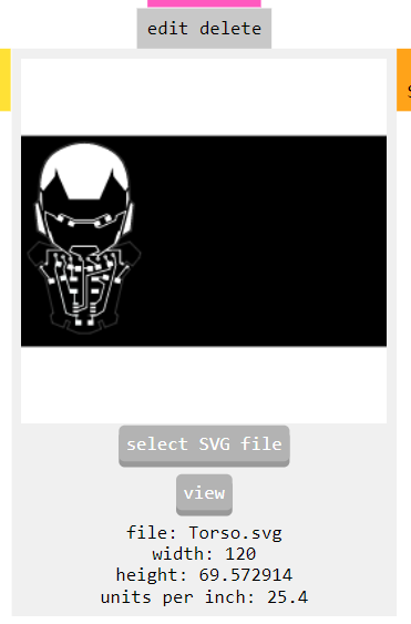
Torso files:


SVG file for Torso Traces
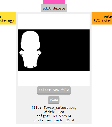
SVG file for Torso Cutout

SVG file of the traces for the rest of the parts
SVG file of the cutouts of the rest of the parts
I am also including the combined version of the torso and the rest of the parts:

SVG files of the cutouts of all the parts
SVG file of the traces of all the parts
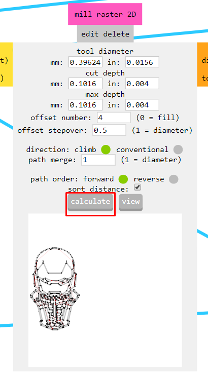
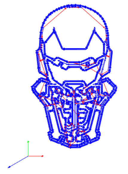
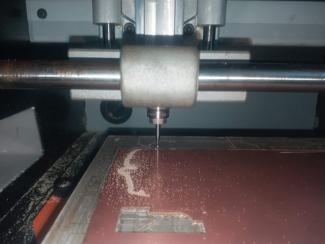
Milling the parts for the Ironman board:
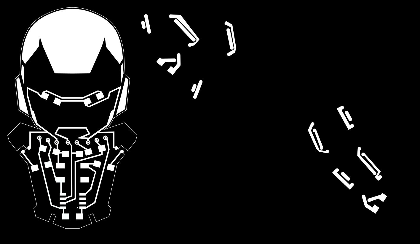
Traces
Cutout
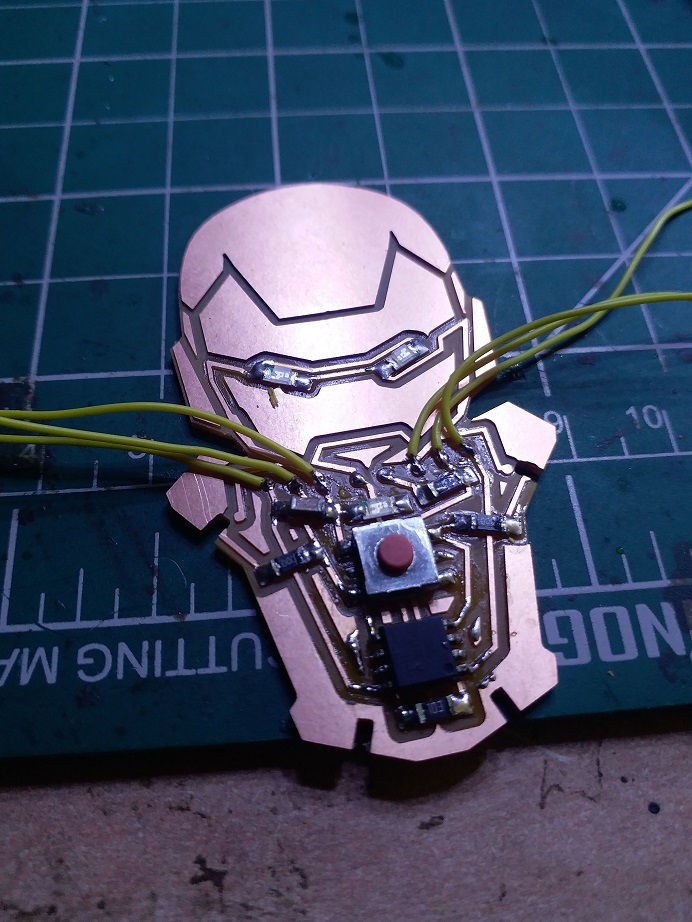
Soldering:
Programming:
I modified the code in the Arduino IDE File>Examples>Basics>Fade
/*
  Fade

  This example shows how to fade an LED on pin 9 using the analogWrite()
  function.

  The analogWrite() function uses PWM, so if you want to change the pin you're
  using, be sure to use another PWM capable pin. On most Arduino, the PWM pins
  are identified with a "~" sign, like ~3, ~5, ~6, ~9, ~10 and ~11.

  This example code is in the public domain.

  https://www.arduino.cc/en/Tutorial/BuiltInExamples/Fade
*/

int led = 1;           // the PWM pin the LED is attached to
int brightness = 0;    // how bright the LED is
int fadeAmount = 1;    // how many points to fade the LED by

// the setup routine runs once when you press reset:
void setup() {
  // declare pin 9 to be an output:
  pinMode(led, OUTPUT);
}

// the loop routine runs over and over again forever:
void loop() {
  // set the brightness of pin 9:
  analogWrite(led, brightness);

  // change the brightness for next time through the loop:
  brightness = brightness + fadeAmount;

  // reverse the direction of the fading at the ends of the fade:
  if (brightness <= 0 || brightness >= 150) {
    fadeAmount = -fadeAmount;
  }
  // wait for 30 milliseconds to see the dimming effect
  delay(30);
}
Fading LEDs sketch
Output: