Mohit Ahuja's Fabacademy 2021
3D Scanning and Printing
Group Project
We tested the parameters of the machine using the testfiles provided by Neil. I wanted to present the test files in a unique way, so I tried to make a stop motion animation video for the first time in my life. This is what I came up with.
Link to the group project
3D Scanning
3D Sense
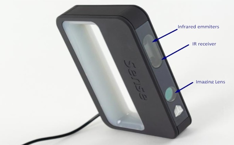
The 3D sense scanner is a handheld 3D Scanner which is capable of recreating 3d models of real world objects to scale and make a visual representation of them. It does so by using a combination of photogrammetry and IR Grid mapping. This way we get a colored output with the shape of the object.
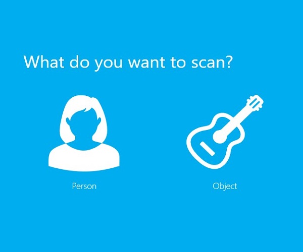
This is what you will see when the software is ready to scan an object. I chose person since I wanted to scan myself.
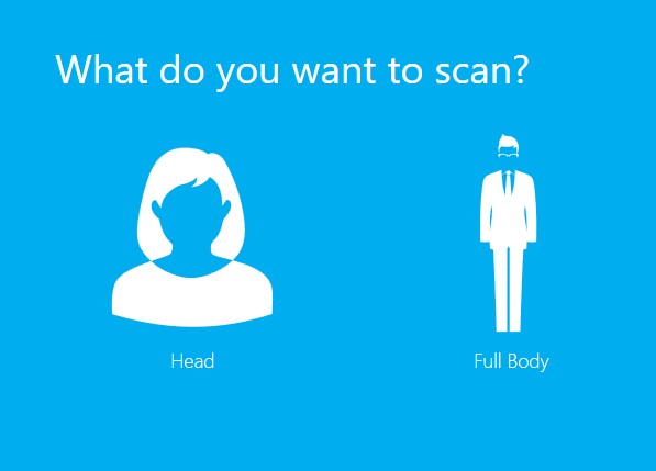
After that I chose head, since I only wanted to scan that area.
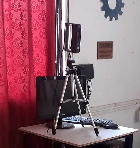
This is how we setup the scanner to scan ourselves. One person sat on the laptop and made sure that the scan went properly.
It took a few tries but I was eventually able to produce a scan. It is a big file, so I have uploaded it to Sketchfab. The following was the result of the process:
While scanning, there were a few things that I needed to take care of:
- I had to make sure that I was in a well lit area from all directions. Because otherwise the scan did not register properly.
- While scanning, I had to move steadily otherwise the scan would turn out poorly.
- Any transparent and reflective objects will have to be removed because as you might be able to see in the scan, my spectacles did not appear in the scan at all.
Qlone (Photogrammetry)
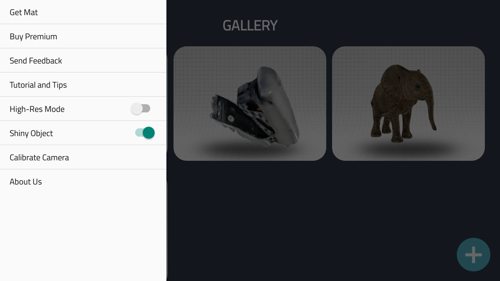
Qlone is a photogrammetry app, meaning that it uses photos to create a 3D model by stiching them together using an algorithm. To create a reference for the image, qlone uses a mat with a pattern that tell the software about the location and distance of the object from the camera. I opened the app and got the map as seen below.
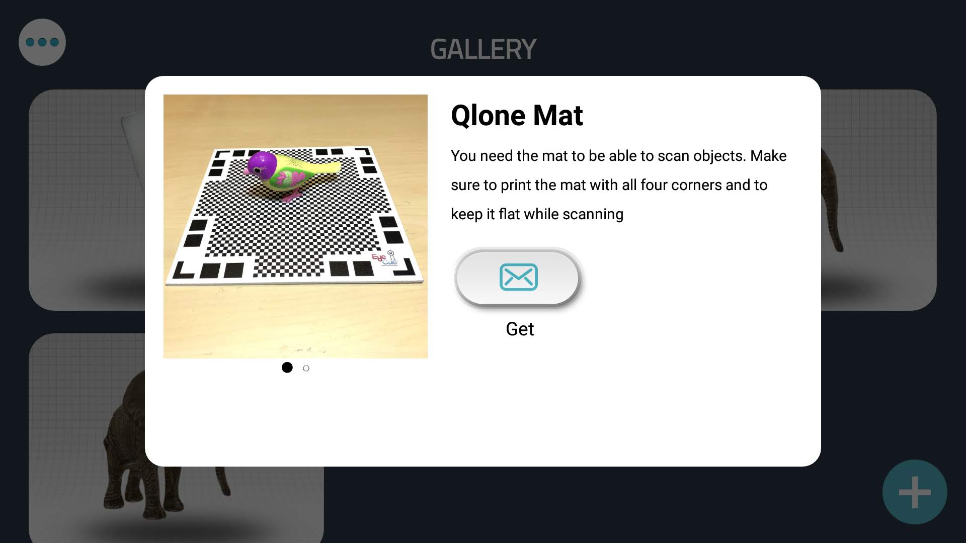
This is the Qlone map, which needs to be placed beneath the object being scanned. Based on the size of the object, you can either scale up or scale down the map so that it fits in the map. Click here to get the map.
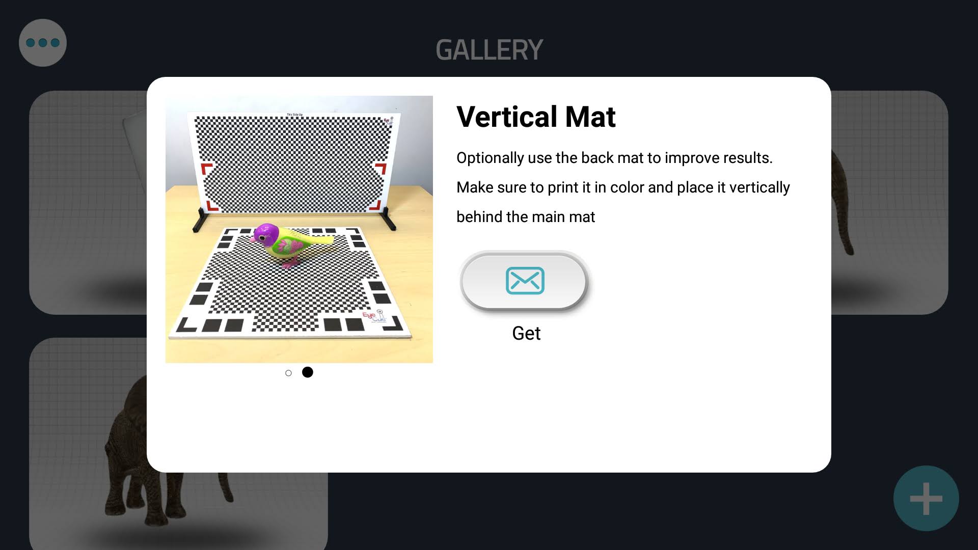
This is the vertical map. It is useful but optional.
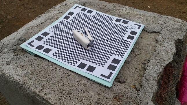
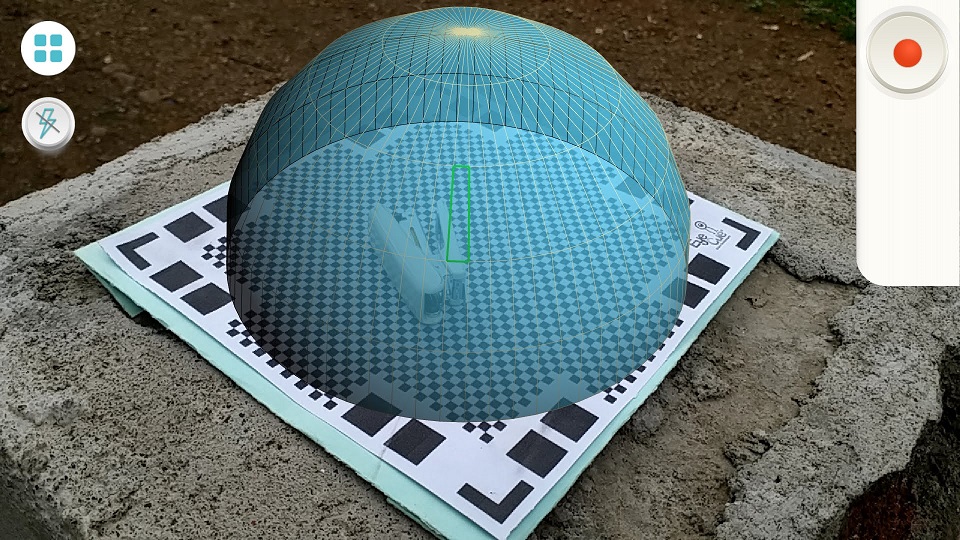
I chose to scan this mini stapler and this is how i set it up for scanning:
After clicking on the plus button on the bottom right side of the screen, we can start the process of recording images. Notice the blue dome that covers the stapler. This dome helps us in taking the pictures, as we move and capture the stapler from different perspectives, it will start becoming more and more transparent.
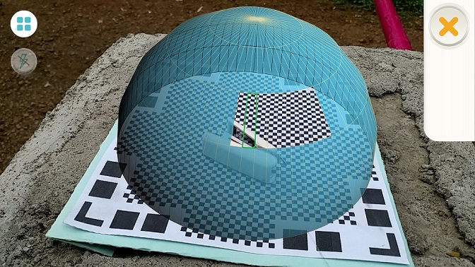
Here you can see what I am talking about. After enough images have been captured, you can also see the 3d model being constructed simultaneously in the bottom right of the screen.
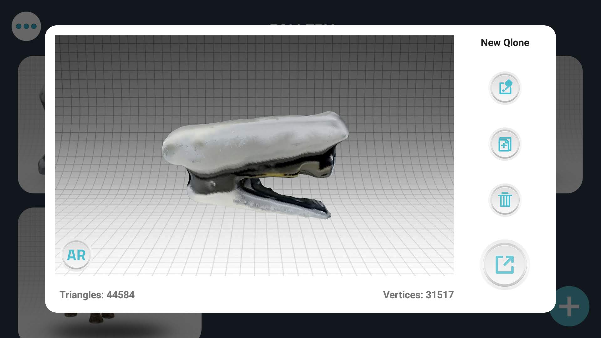
And finally here is the finished scanned model. Surprisingly it was pretty accurate and only had flaws where there were some shiny bits in the image. Although it took me a few tries to get to this result too but it was worth it.
However, to export an object as a 3D model, we need to pay for the premium features of the app. It lets us share to sketchfab and also lets us create videos and gifs from it for free.
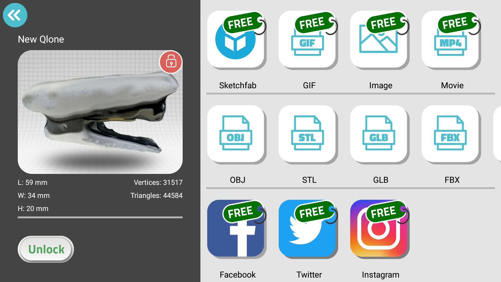
So here is the result shared to Sketchfab.
3D Design and Printing
TinkerCad
Tinkercad is a beginner friendly CAD tool developed with the purpose of involving young minds into CAD design. It has a very simple interface and I have used it extensively to teach CAD design to students. I was initially not going to use tinkercad at all, but one of our fabacademy colleagues, Vijay Sir had found a video on youtube that showed how to use Tinkercad to make a beautiful vase by radially repeating a simple curve. This is the video that he shared:
After seeing this video, I knew that I absolutely had to try this out. So I made a basic design first. Here is a timelapse of what I did:
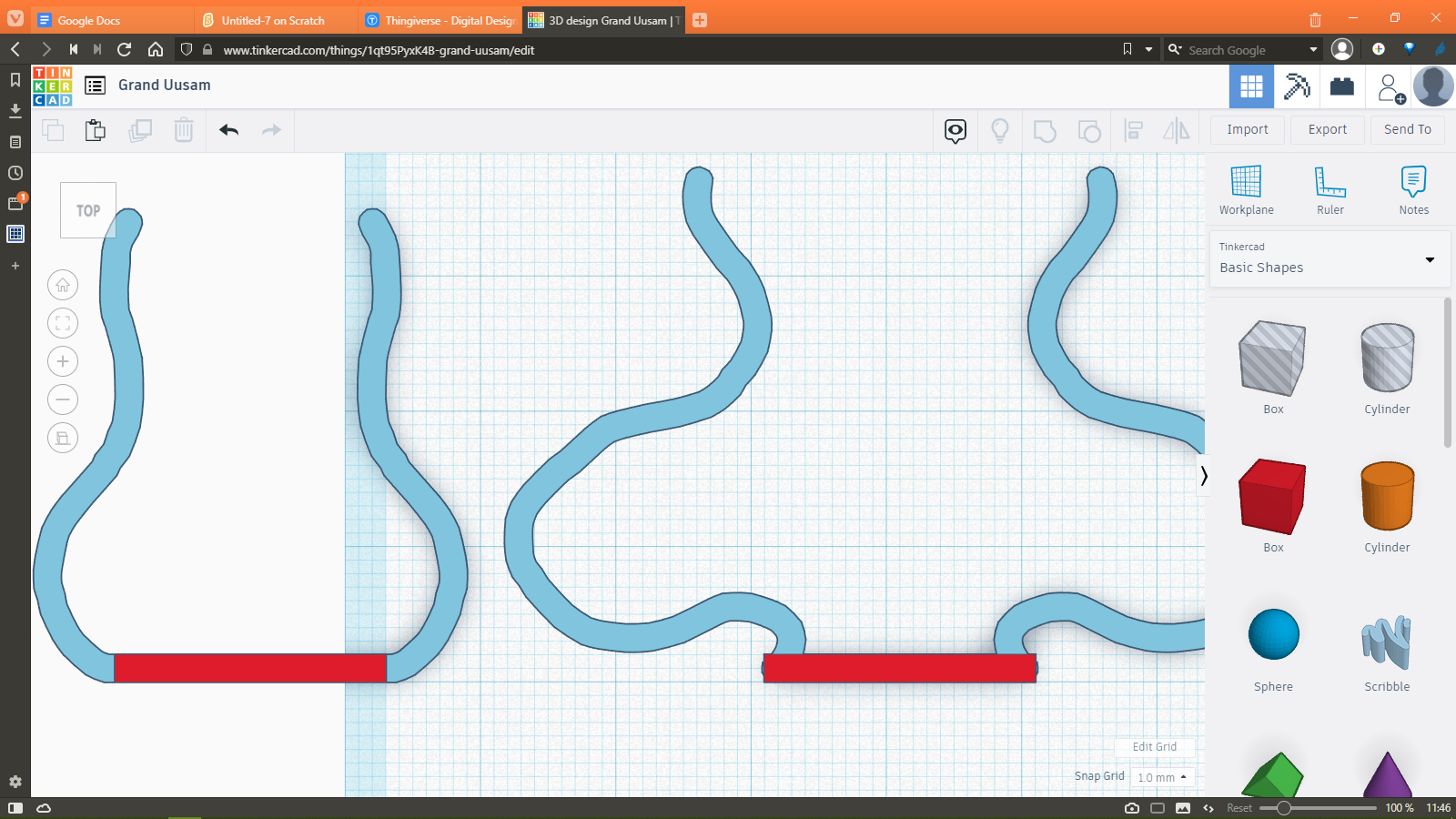
After seeing the results of that, I had more ideas. First of all, I wanted to make a vase that is nested within another vase and is designed in such a way that you could see the inner vase from the slats of the outer vase. I did this by making two 2D shapes like below using the scribble tool and the box tool:
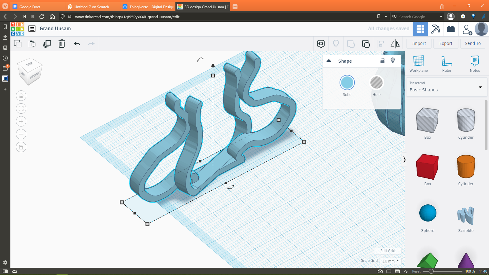
I then use the rotate tool to first make both the curves stand on the flat base. Then by using the align tool I combined the central axes of the curves in such a way that they overlap. After that, I slightly offset the smaller curve by an arbitrary angle and then by using the group tool I combined both of these shapes into one, which resulted in this:
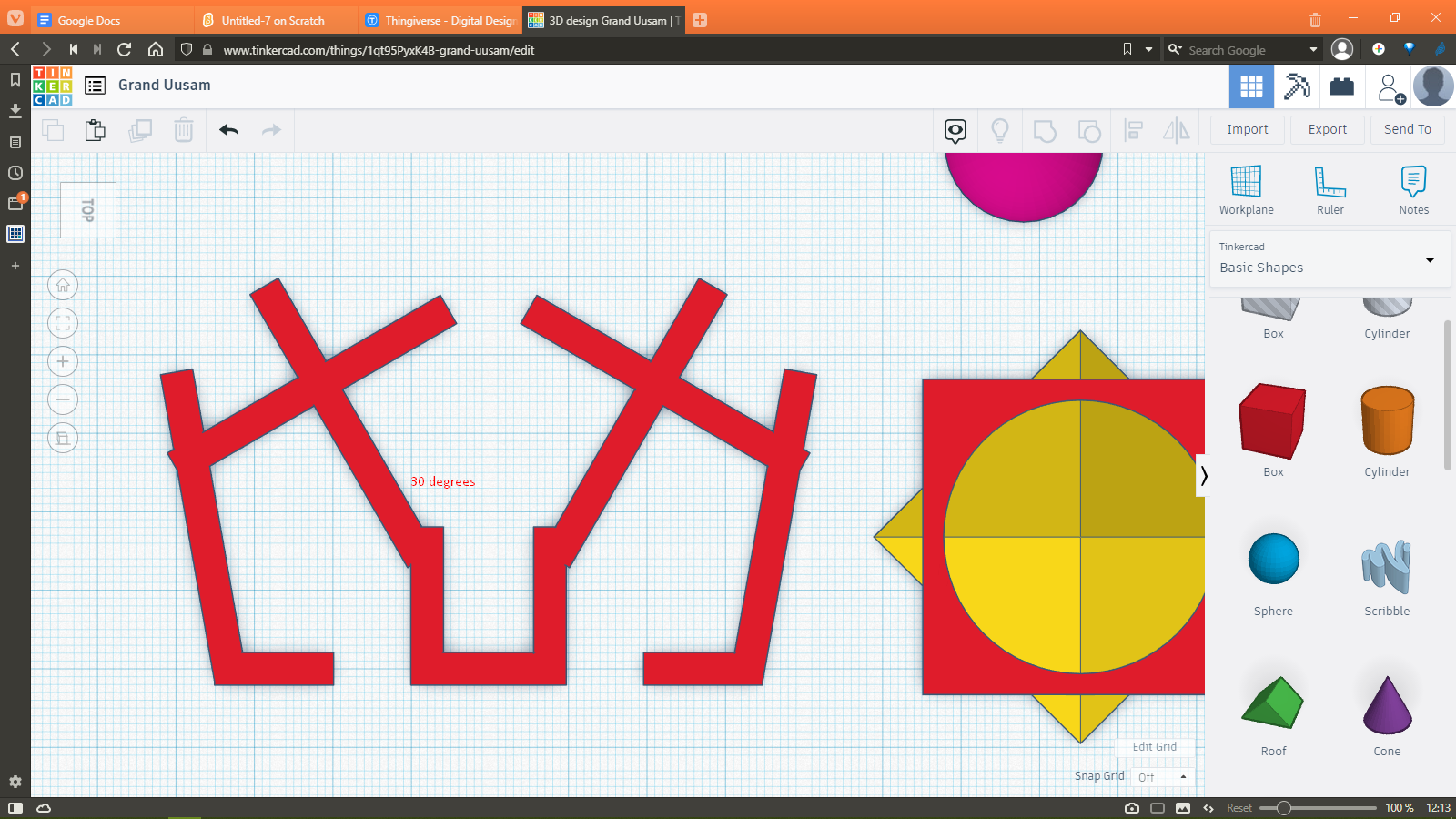
I then copied and rotated this shape in such a way that these was a little gap in the outer vase.
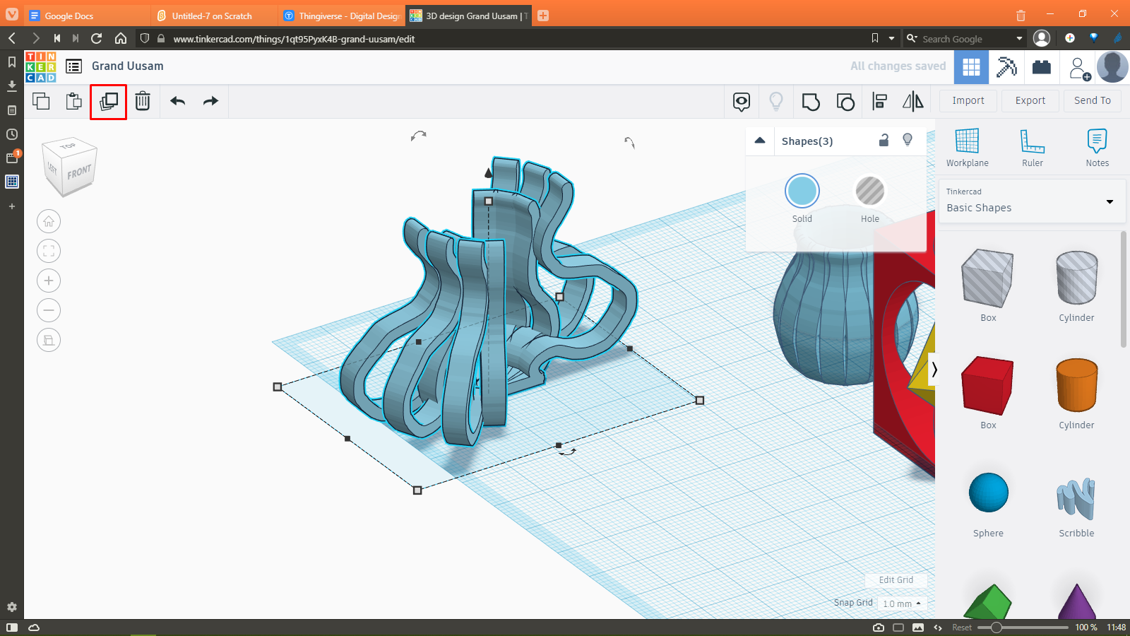
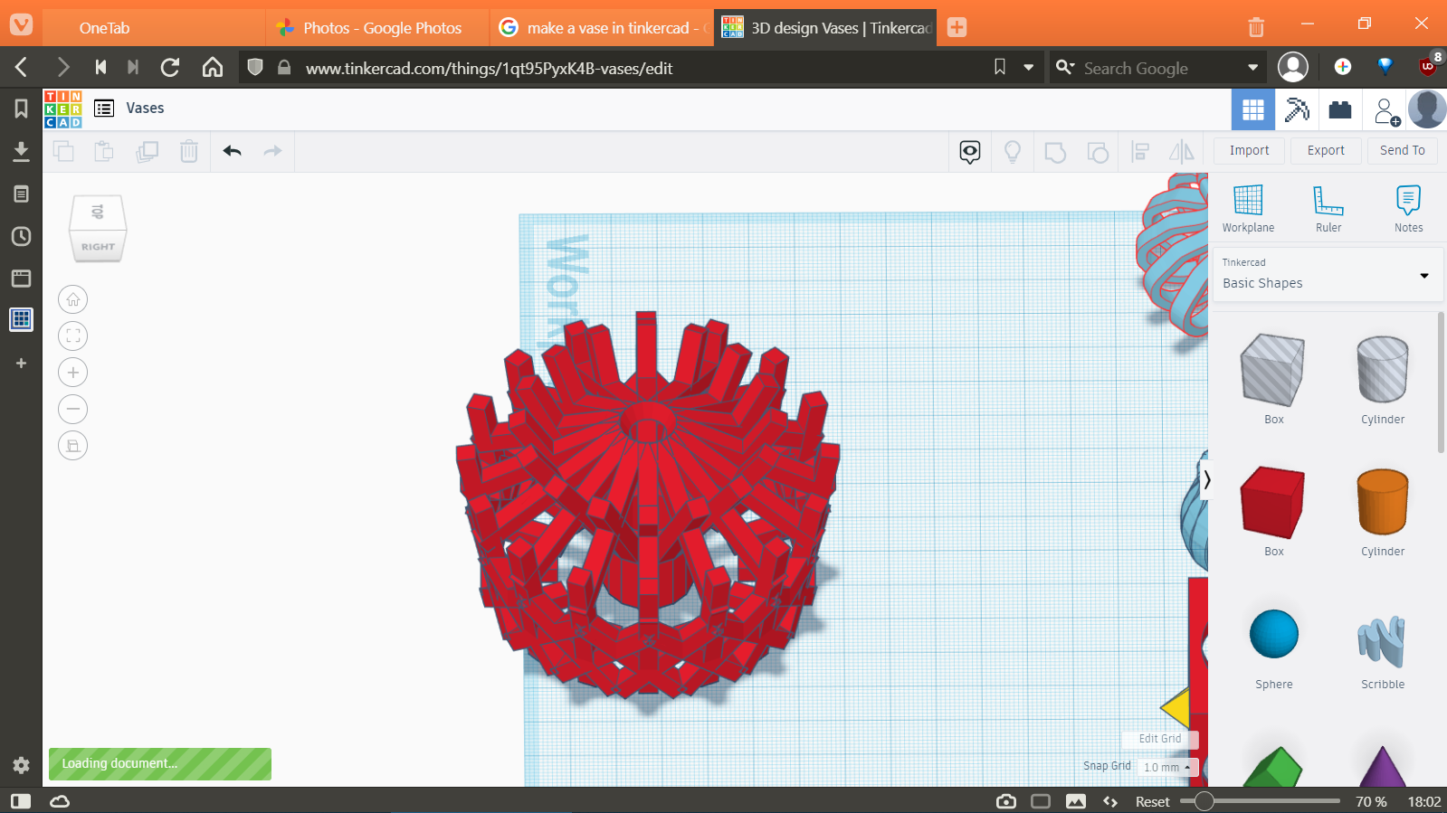
Then by using the duplicate tool, the rotations were repeated until the entire vase shape was formed.
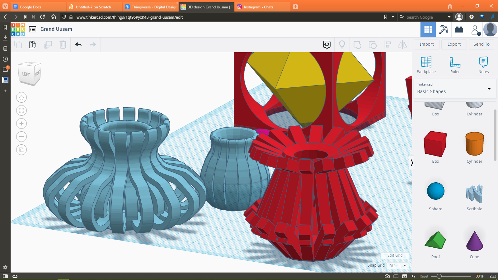
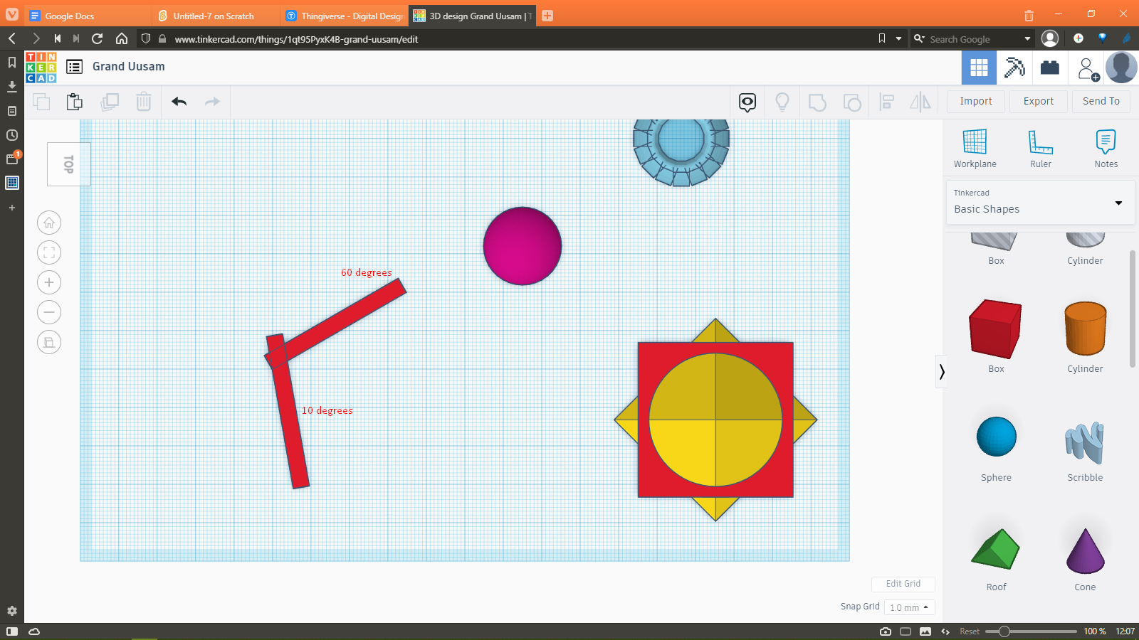
I also had an idea for a new kind of overhang test where a vase can have overhanging parts at different angles. So instead of having a single bar of different overhang values like the one given by Neil in his testfiles, we could actually use the vase as a decoration piece as well as a test print. To make it, I first reshaped and arranged some boxes into different lengths and angles to make the outline to be repeated for the vase. This is what I came up with:
Here is the tinkercad file for the different vases. I did not print them due to time constraints and the fact that the machine had to be shared amongst 4 other fabacademy students. I also plan to make the parts thinner so they can be printed with less material and also act as a stringing test.
Rhino Model
Trial Joint
Here I used Rhino to make a Print-in-Place mechanism. I wanted to make a full body mechanism but before I could do that, I needed to make sure that the parameters for the gap between moving parts is dialled in correctly. So I started with this simple mechanism which allows me to test the joints that I will be using in the full body mechanism. Below you can see a timelapse of the entire process of designing the part.
These are the essential steps for making the model:
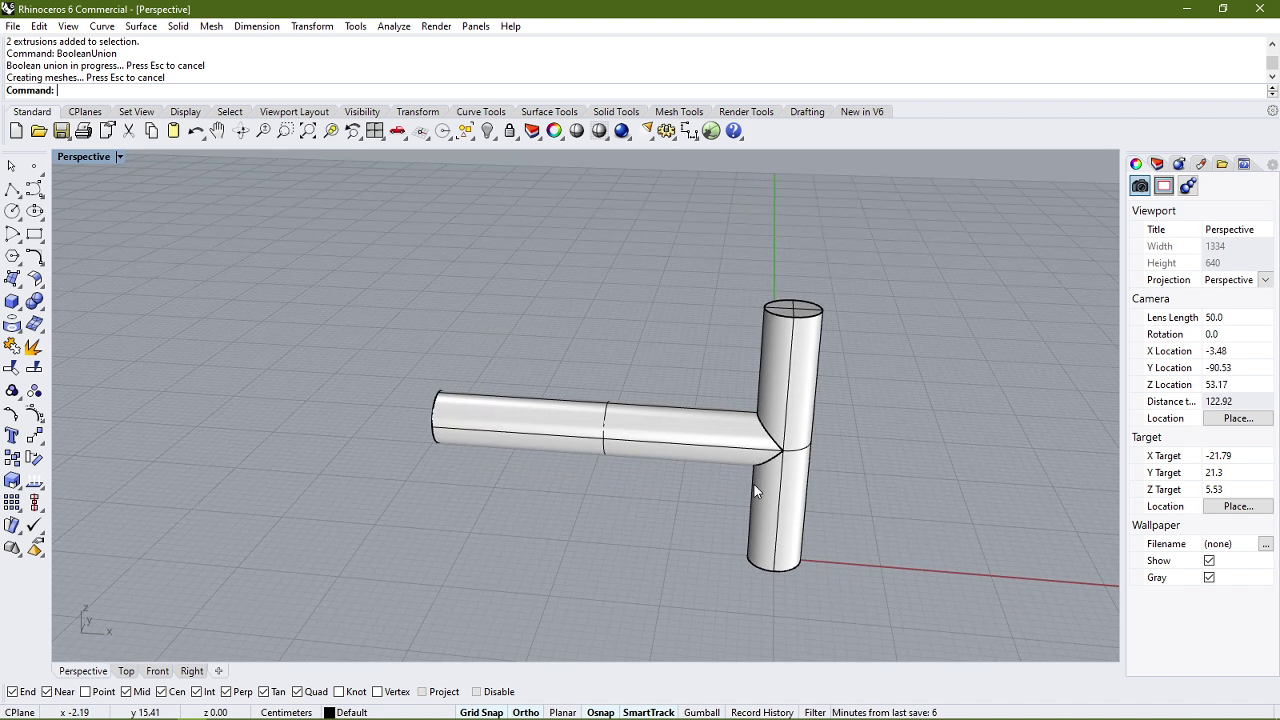
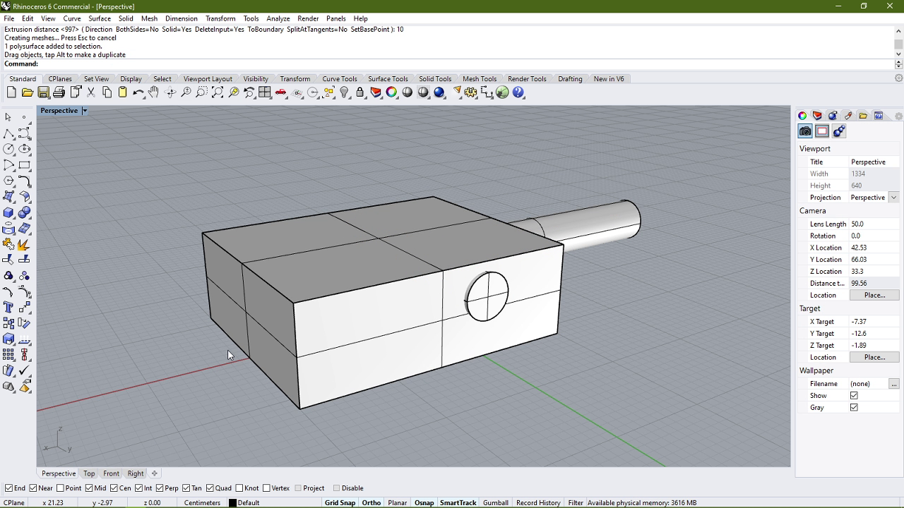
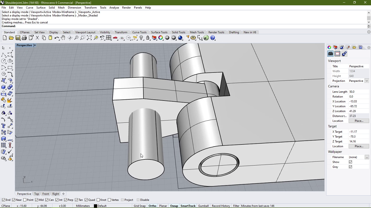
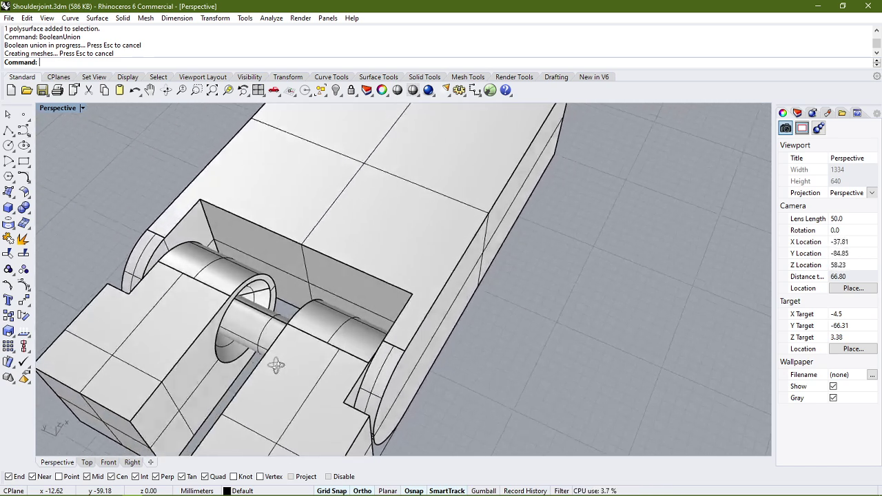
- I started with making the hinge part of the model by simply connecting two cylinders of 5mm dia each perpendicularly.
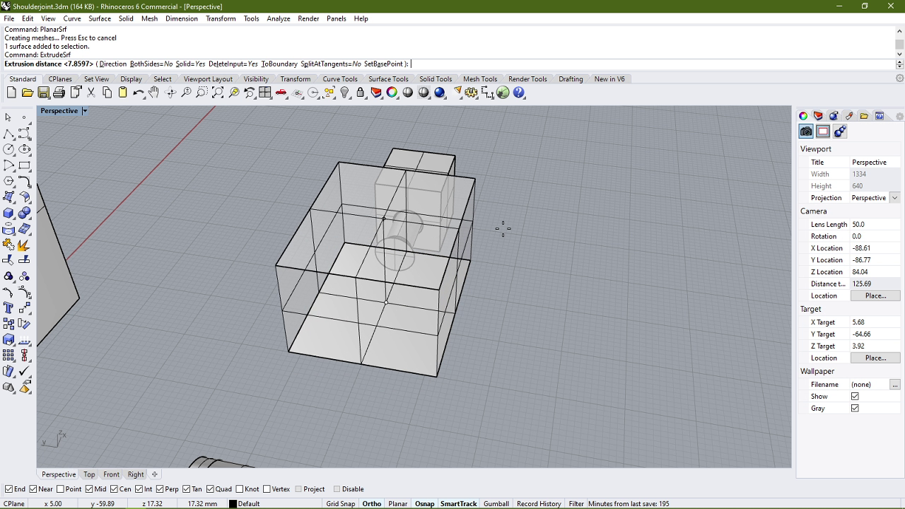
- After that I created a cuboid which acts as the main body of the mechanism, and placed the previously created shape inside the cuboid.
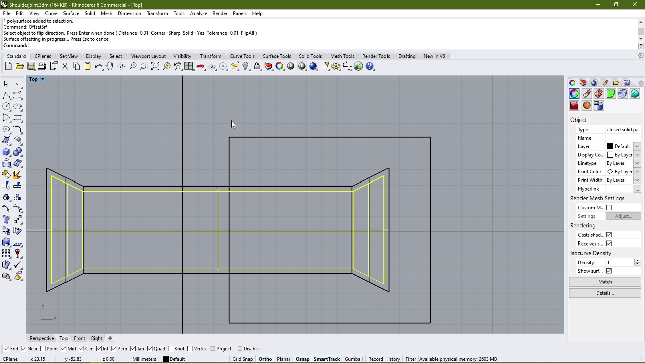
- I then offset the shape and subtracted it from the cuboid. The offset distance was 0.31mm at first.
- After subtracting the offset shape, I cut a rectangular hole in the cuboid such that the cylinder rotates freely.
- Then I proceeded to reshape the cylindrical shape into a cuboid-lik shape so that it is easily printable.
- This would be one of the joints that I wanted to test, the hinge joint.
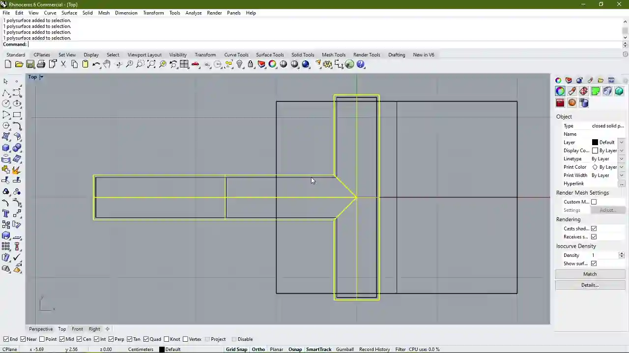
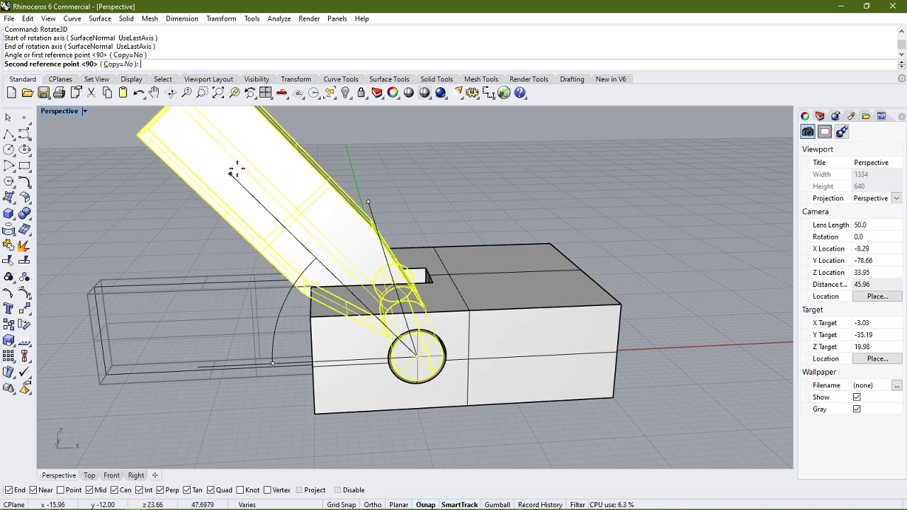
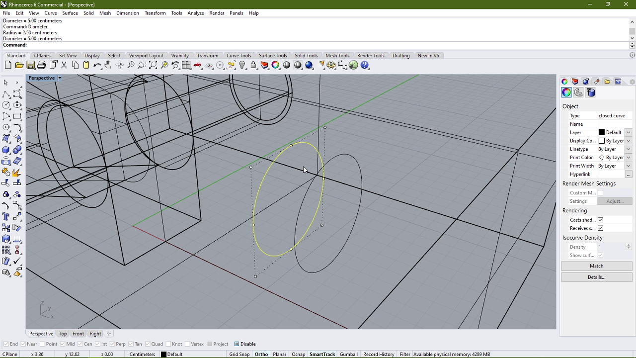
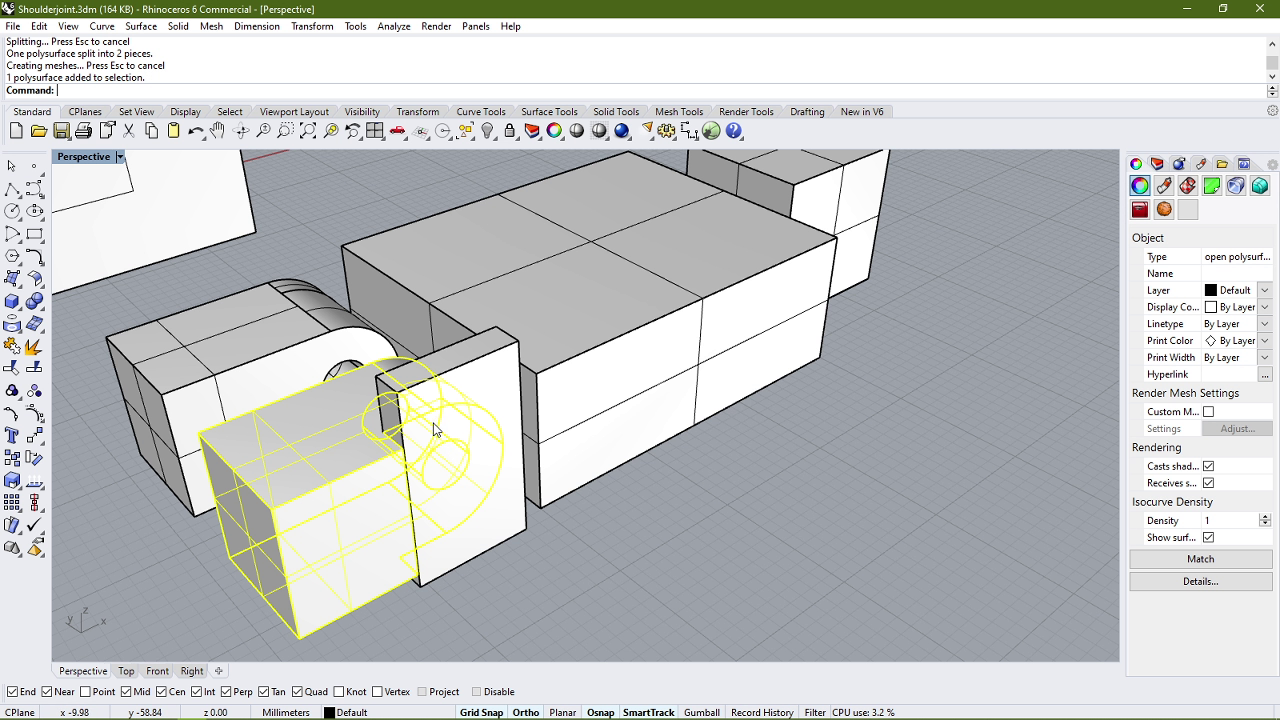
- The next joint that I wanted to test was a swiveling joint, and to make that I began by creating two circles along the same central axis.
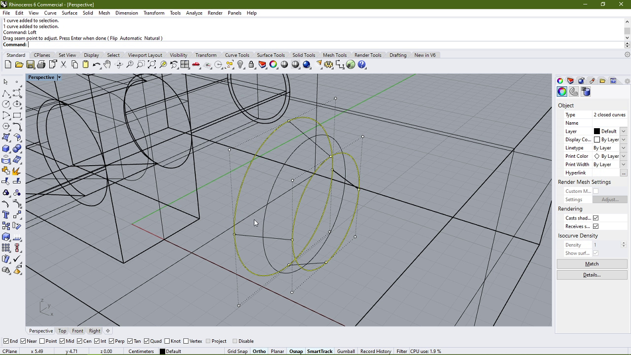
- I then increased the radius of one of the circles and then created a loft between the two circles to make a truncated cone.
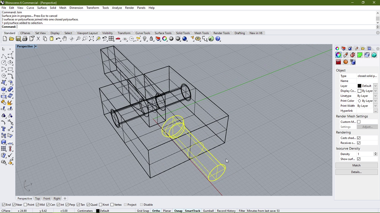
- After that I created a cylinder by extruding the smaller circle outwards from the mechanism's body.
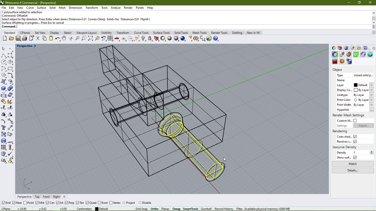
- I then combined the cone and cylinder into a single shape and then offset this shape by 0.31mm again.
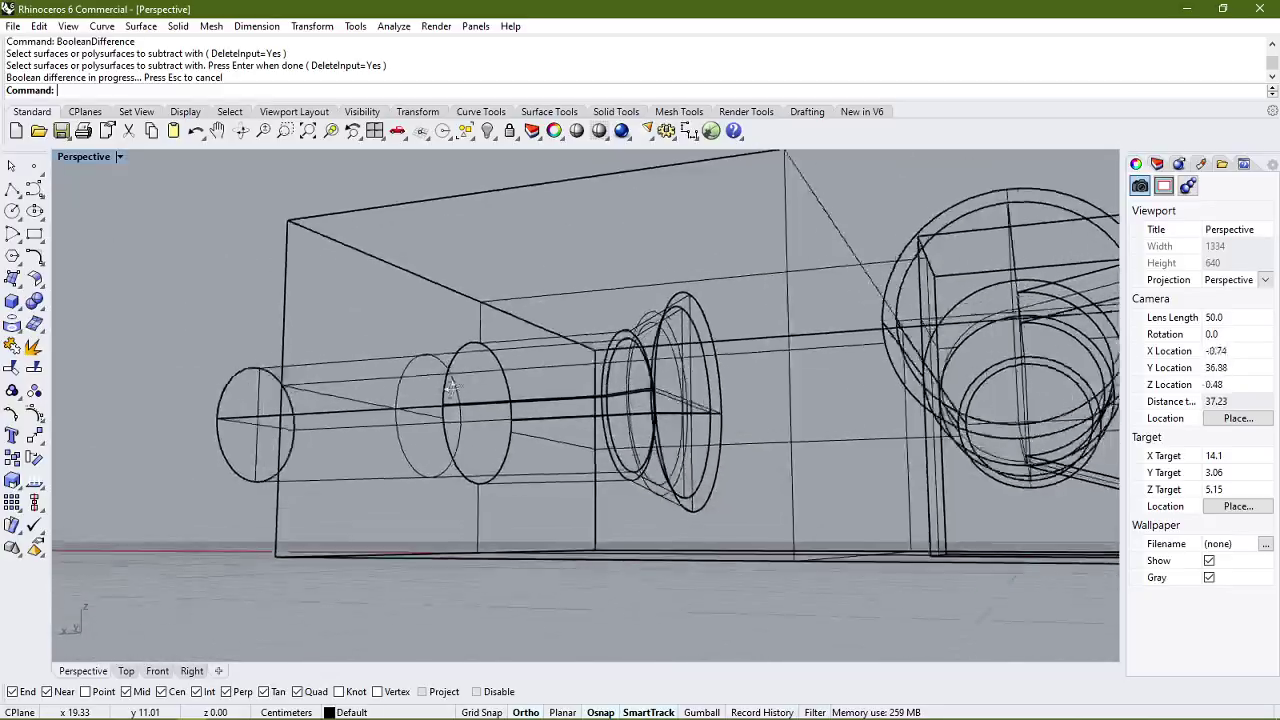
- I then subtracted the offset shape from the main body using BooleanDifference command.
- With that, the full model was ready to test. I exported the model as an STL file so that it can be used with Fraktory, the Slicer for our 3D Printer.
Printing setup
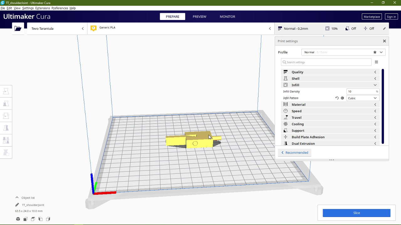
To print the model I used Ultimaker Cura to set the parameters and then used the same parameters in Fraktory. The settings I used were:
- Layer Height: 0.15mm
- Infill Percentage: 10% Cubic
- Print Speed: 60mm/sec
- Filament: ABS
- Bed Temperature: 100°C
- Hotend Temperature: 230°C
- Supports: Touching Buildplate
- Bed Adhesion: Skirt
I also checked the model in the layer view setting to make sure that the print looks fine.
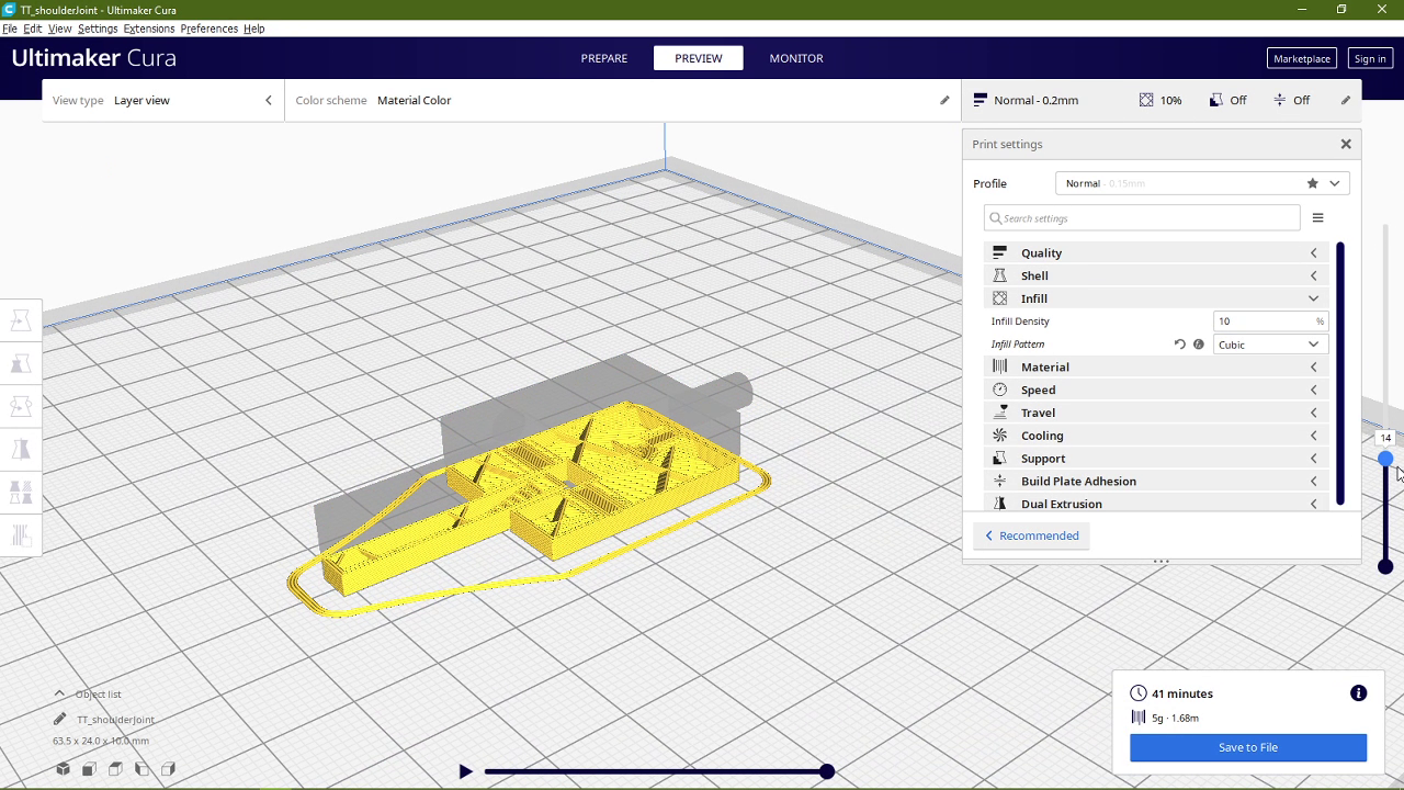
Here is the complete 3D model uploaded to SketchFab.
Due to an issue with the nozzle being jammed, the print got interrupted and we had to remove the nozzle and clean it. But my purpose with the trial was fulfilled. I wanted to see how easy it would be to move the parts after they have been printed together. My conclusion was that the parts did separate but it took some good amount of force. So I decided that 0.31mm is too small for an offset for this mechanism.
Full Model
Designing the Trial joint served one more purpose that I had previously not considered: it acted as a base for my next iteration, i.e. the full body. Here is the steps I took to make the previous design into a full mechanism.
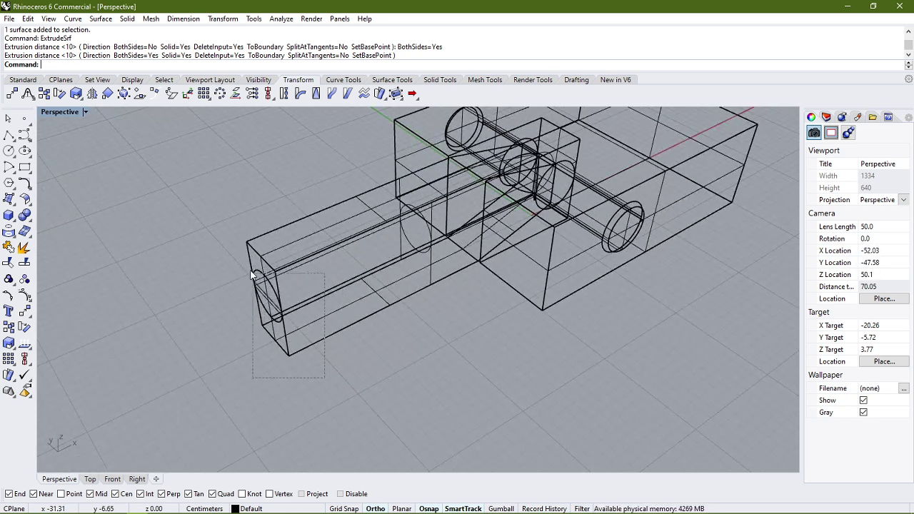
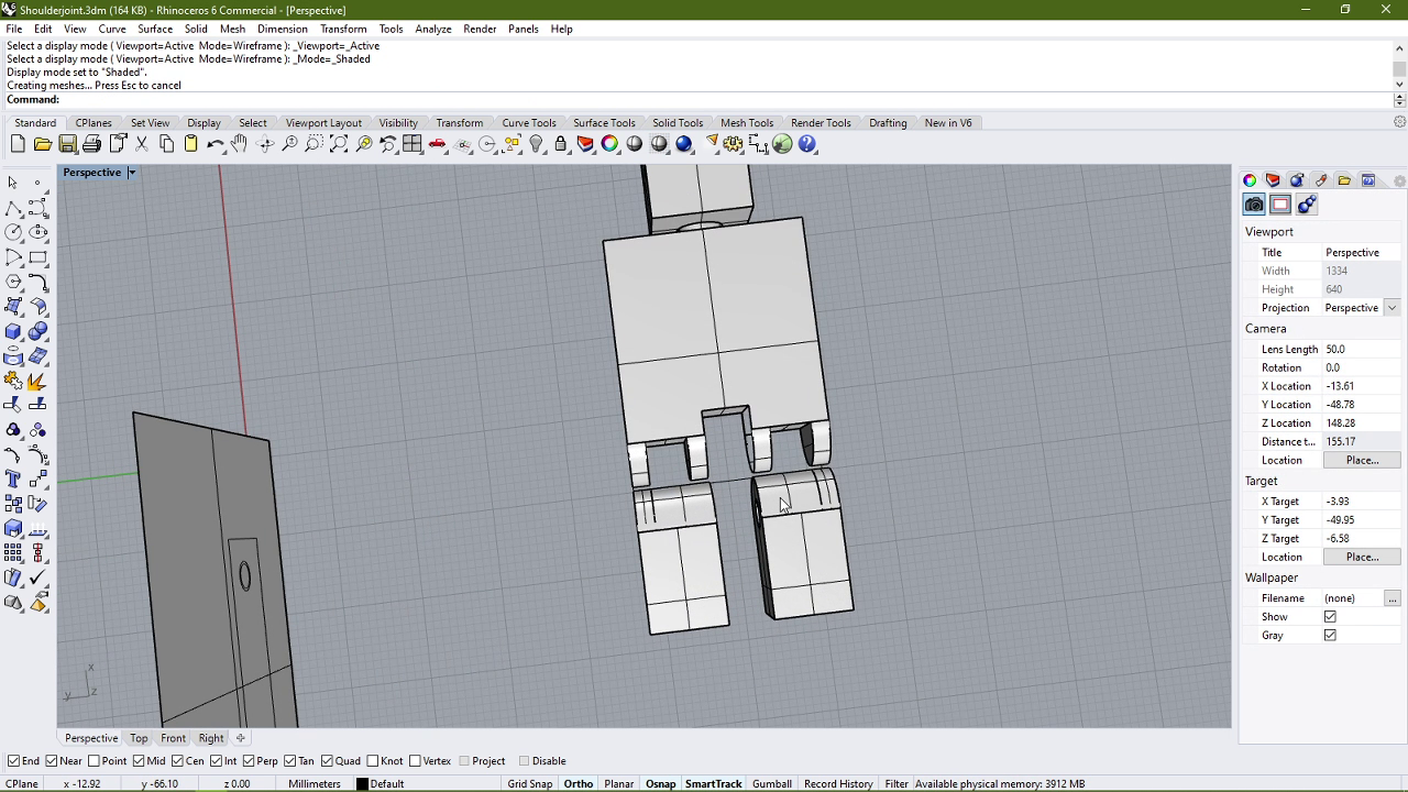
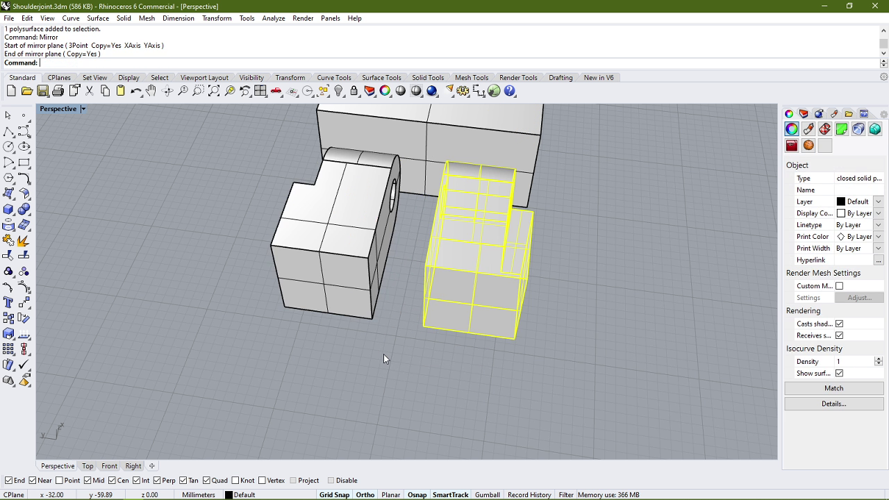
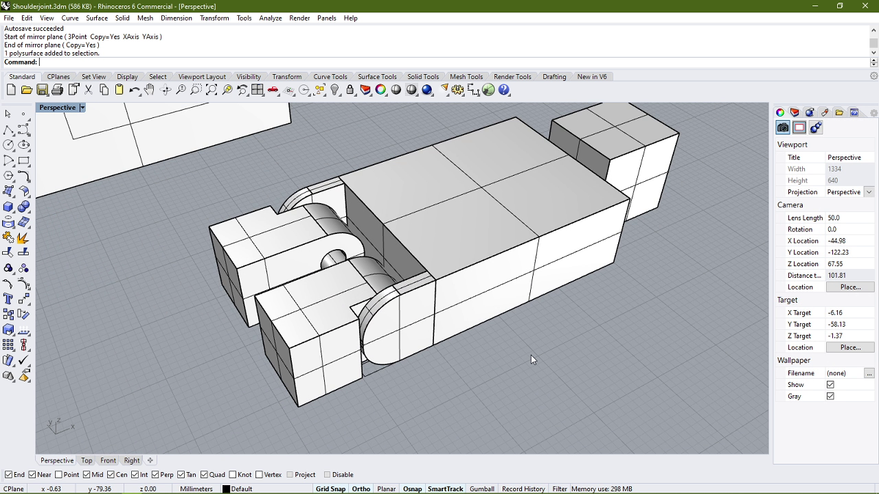
- I started with the swivel joint and mirrored it to create a mechanism for the head as seen below.
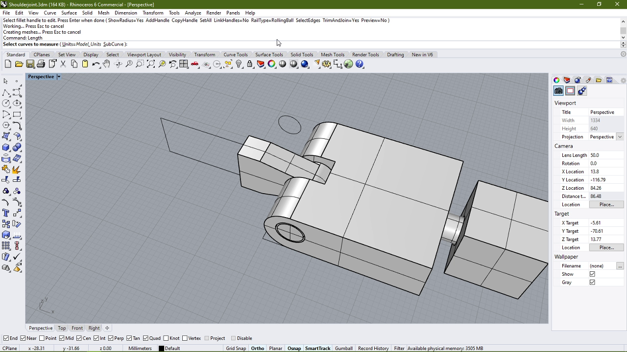
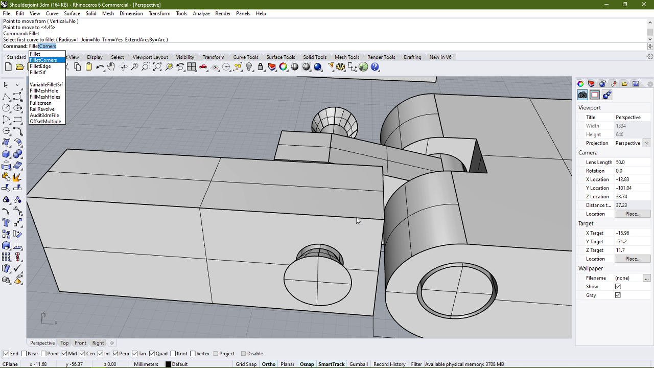
- After that I proceeded to modify the hinge joint to create a mechanism for the legs. I started by shortenind the long hinged part using ExtrudeSrf command:
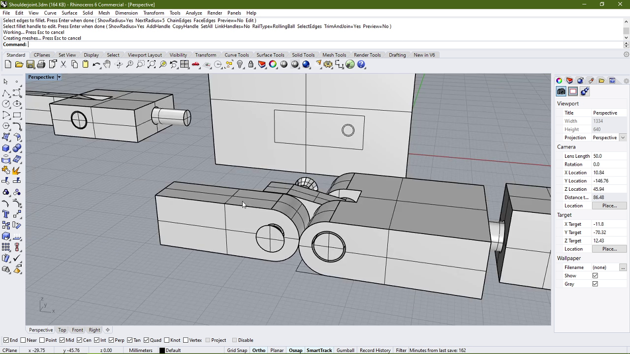
- I then filleted the edges to make them more rounded.
- After that I took a cylinder and combined it with the hinge to make the hip of the body.
- Then I added legs by using the cuboid tool again.
- After that I filleted the legs near the body to make the movement smooth.
- But I was beginning to dislike this approach to connect the legs to the body. So I let go of the hinge joint.
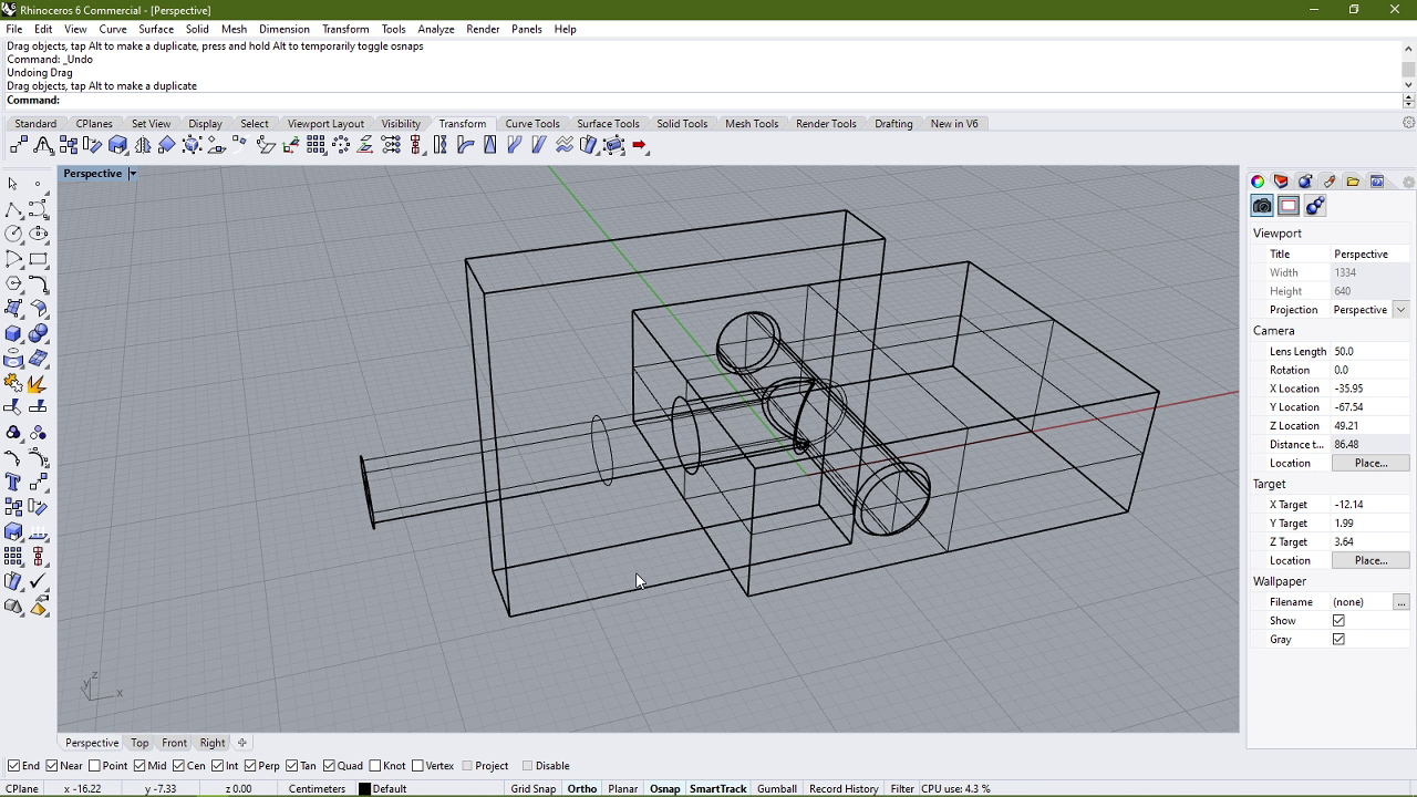
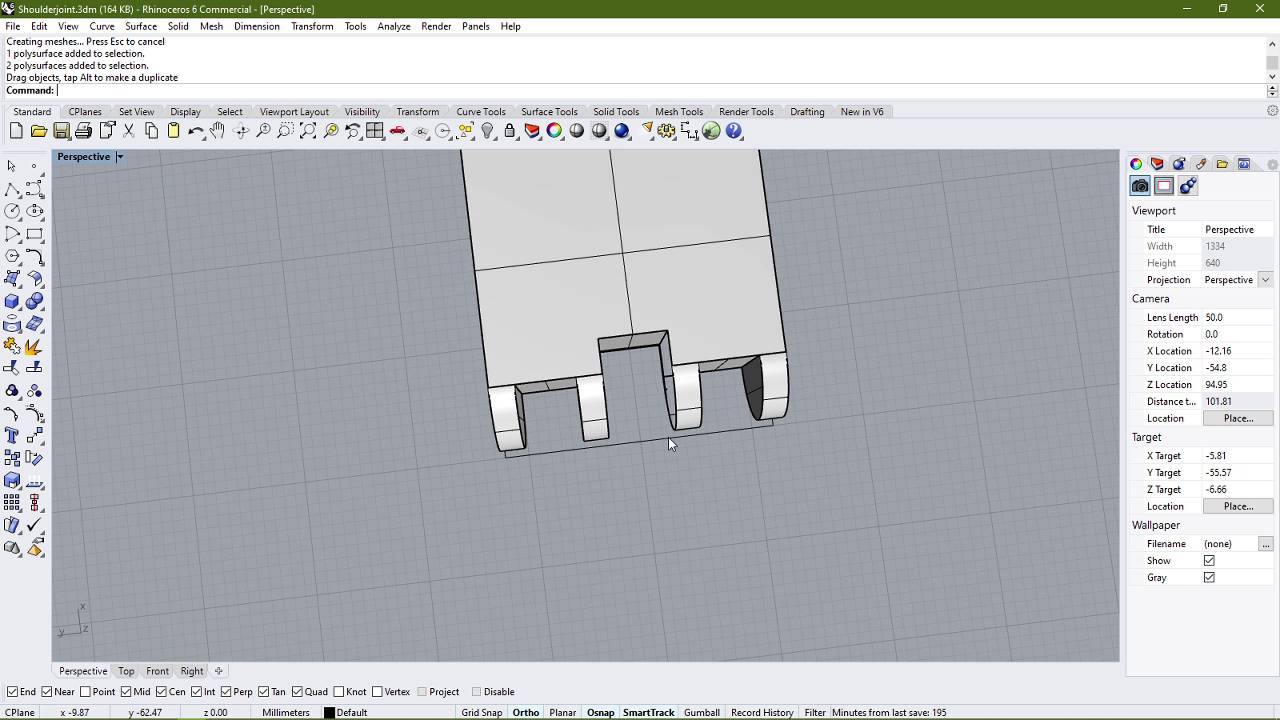
- After that I cut two rectangular holes into the body as shown below, thinking that I might insert the legs into the spaces to make them hinge together.
- I realised that I would have to redesgin the legs for that so I got rid of the previous design.
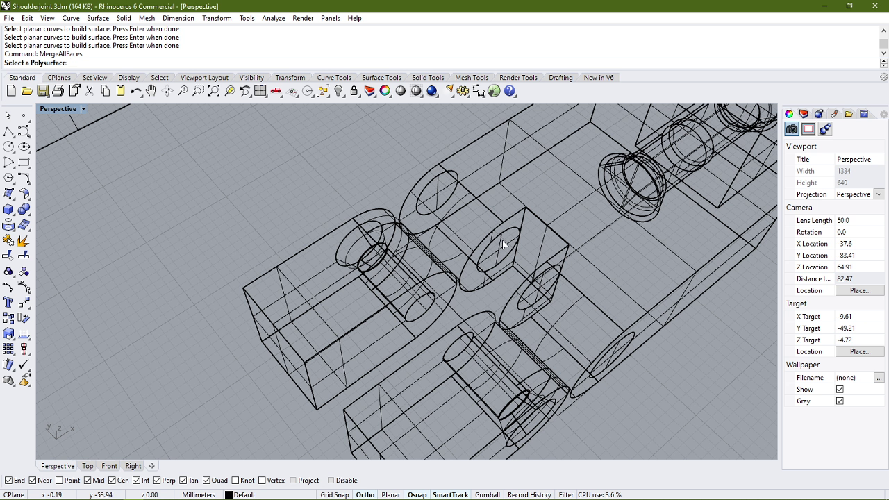
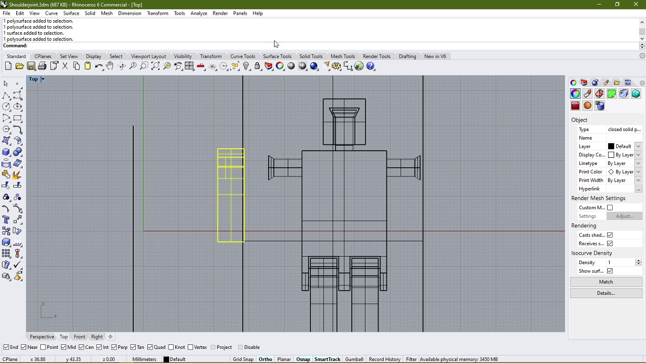
- I then proceeded to discard the entire body and redesign it from scratch.
- I took the legs that were deleted previously and added them back into the model.
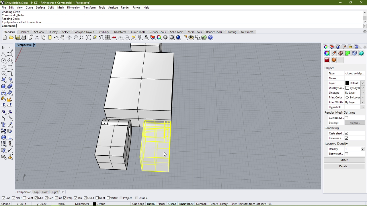
- Then I started by removing a small portion of the legs by placing a cuboid next to the outer side of the leg.
- I then subtracted the cuboid from both the legs.
- After that I added cuboids that were attached to the body and connected with the cutout portion of the legs.
- I also chamfered the inner holes in the legs.
- I ended up disliking the design of these legs as well so I proceeded to delete them.
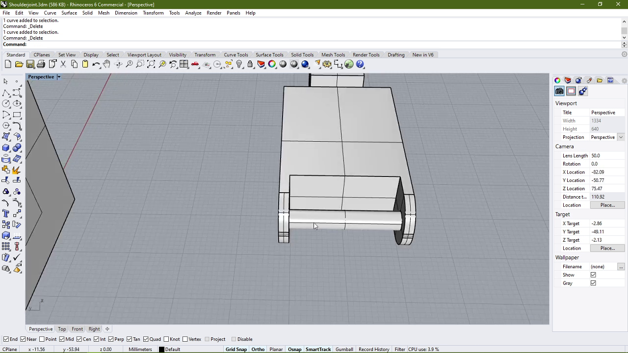
- I added some simple straight legs and I also added a spacer part in between them. I also went and designed the hands by using a technique similar to what I used to make the head swivel: A truncated cone at the base of a cylinder.
- And with that, the Rhino model was completed.

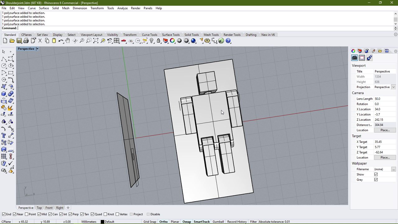
I exported an STL file of the model and uploaded it to sketchfab.
Here are the original files:
STL File of the full model
Rhino file for the Trial and the full body model
Printing setup
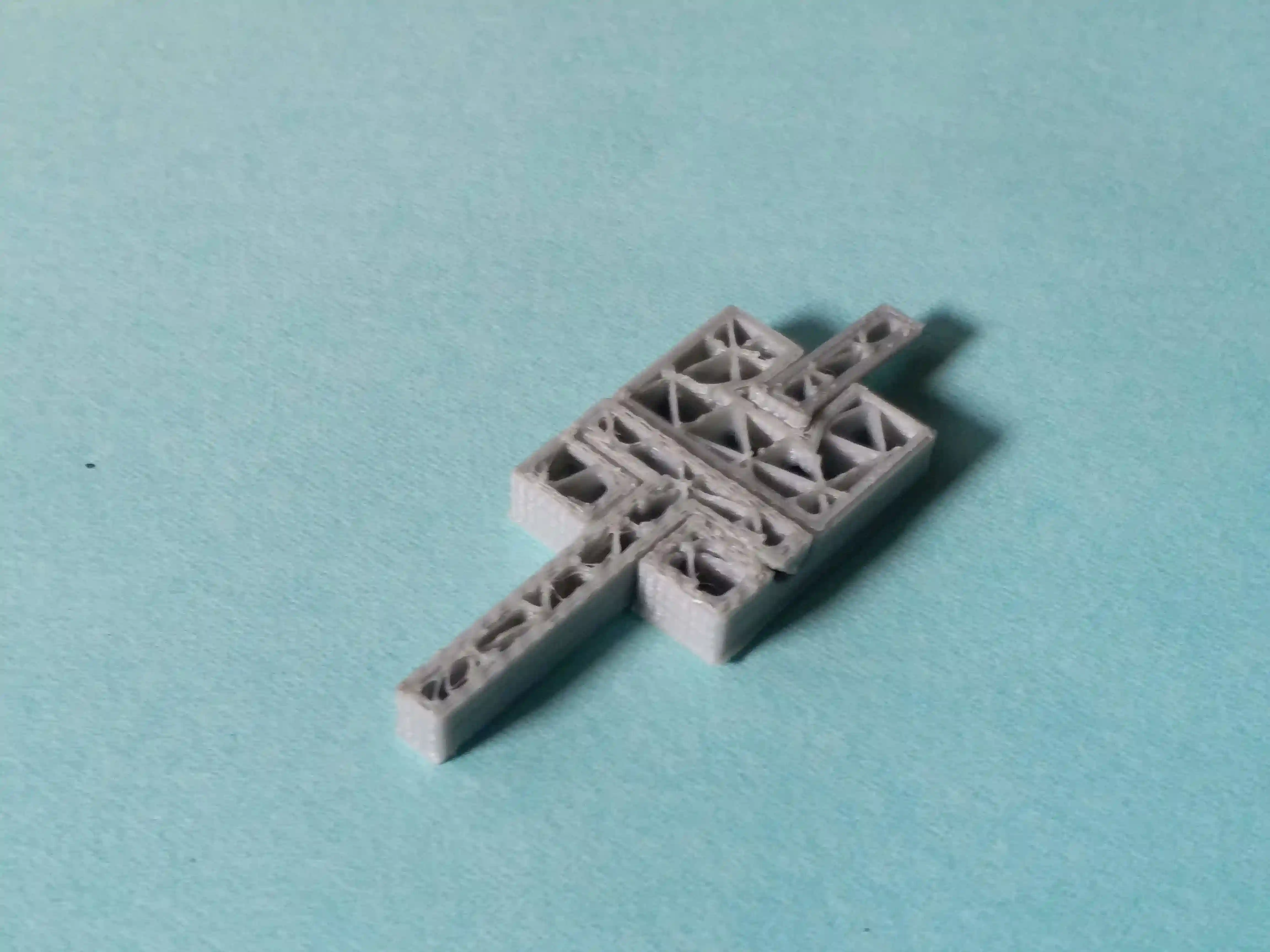
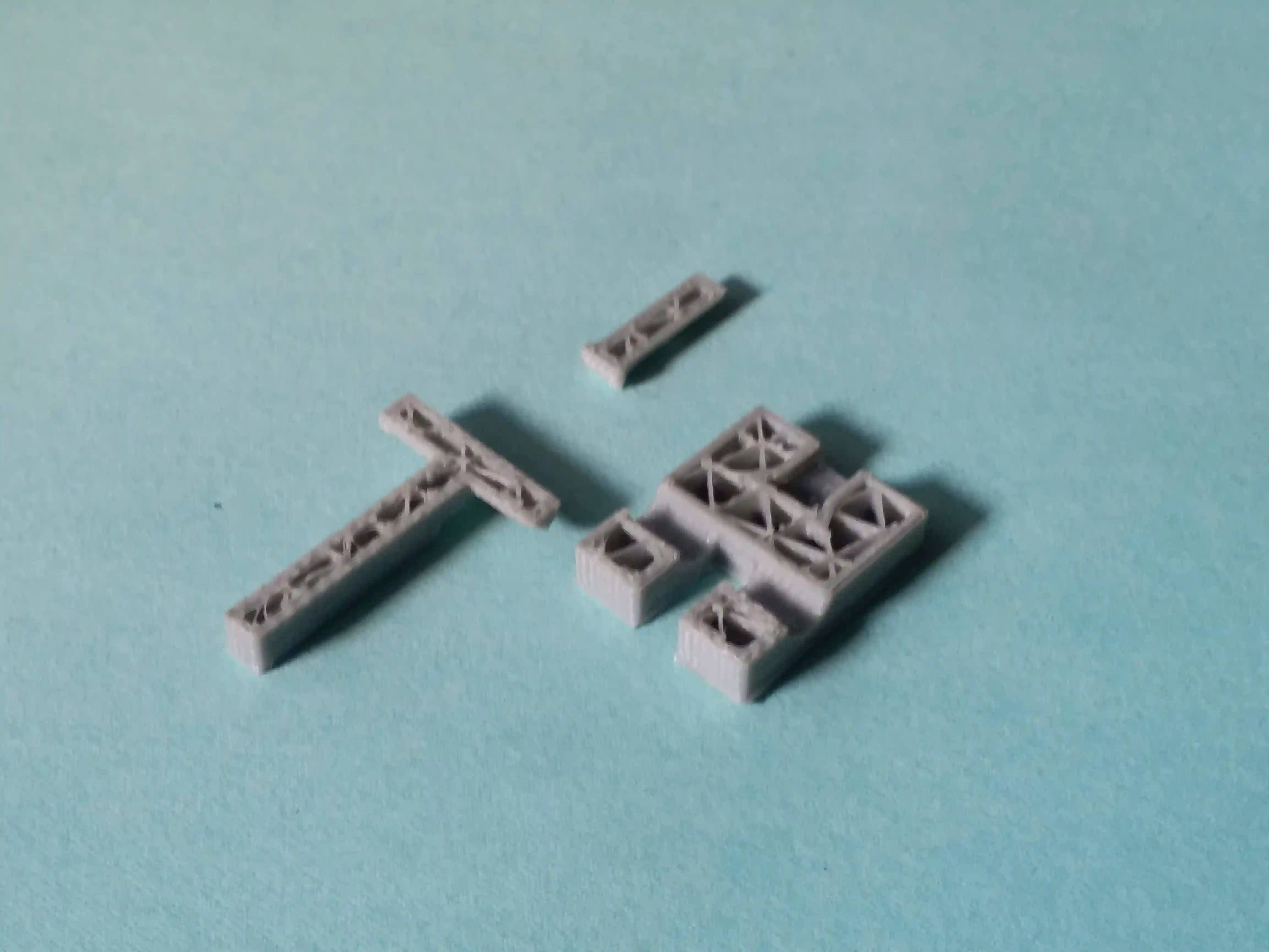
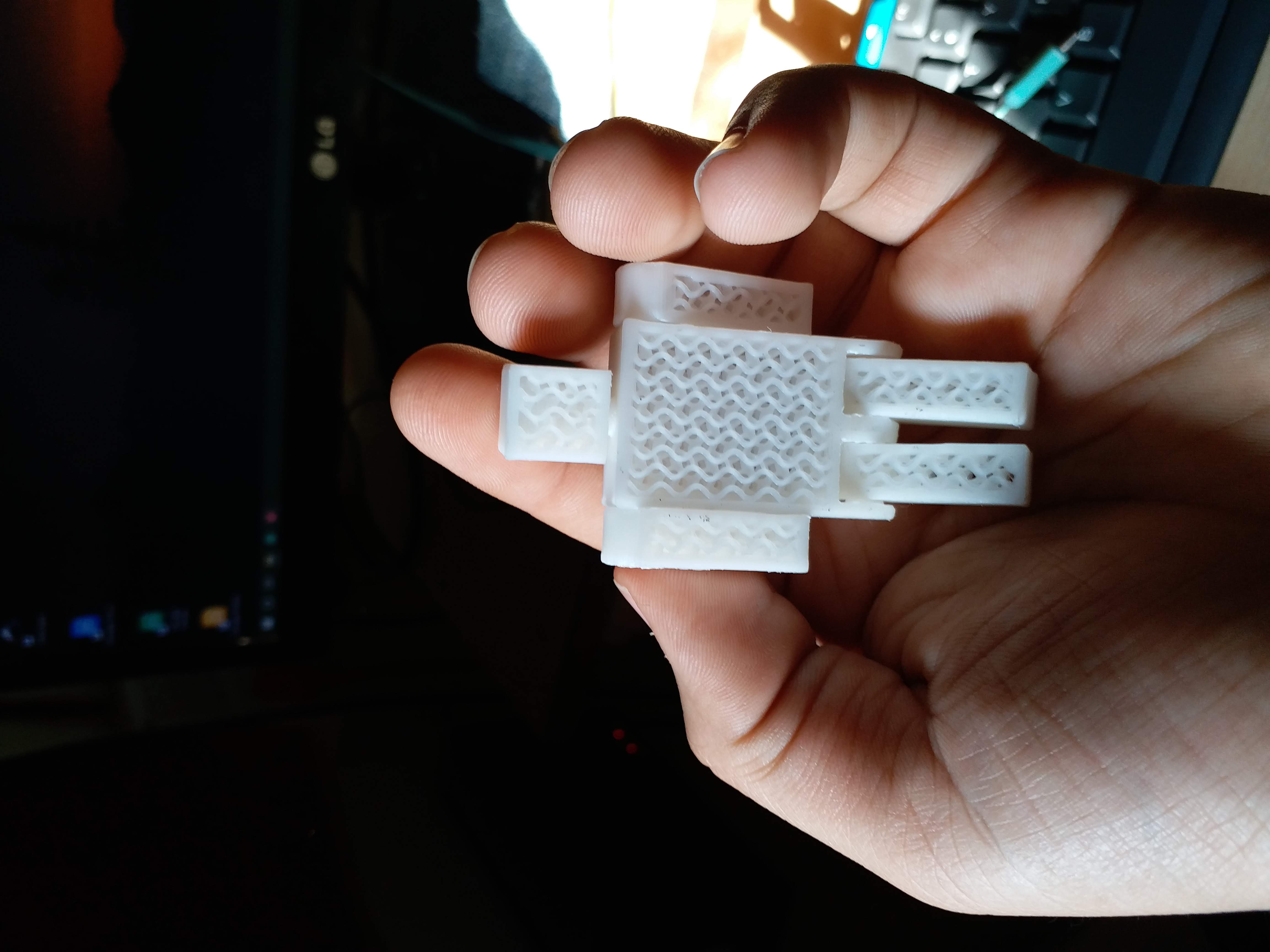
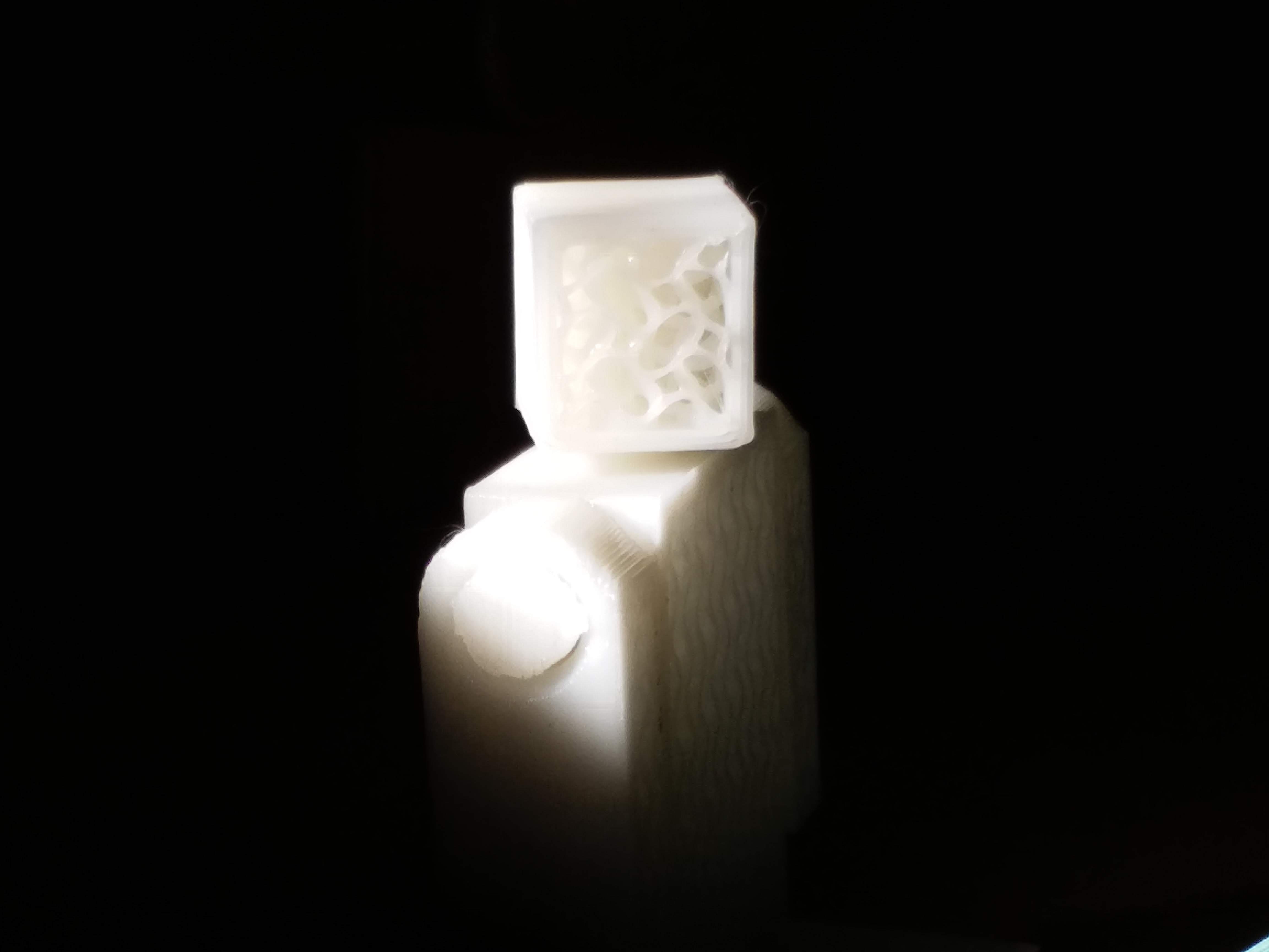
I used PLA to print my model this time around so I had to change my parameters regarding the nozzle and bed temperature to 210°C and 60°C respectively. I had also designed the model to specifically print without any need of supports whatsoever. And just to make things interesting, I decided to print without the top and bottom shells, so that the infill pattern could be observed. Which I chose to be a Gyroid infill, because I thought it would give an awesome look to the model. And this is what it looked like after printing:
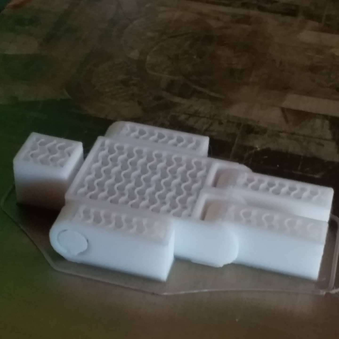
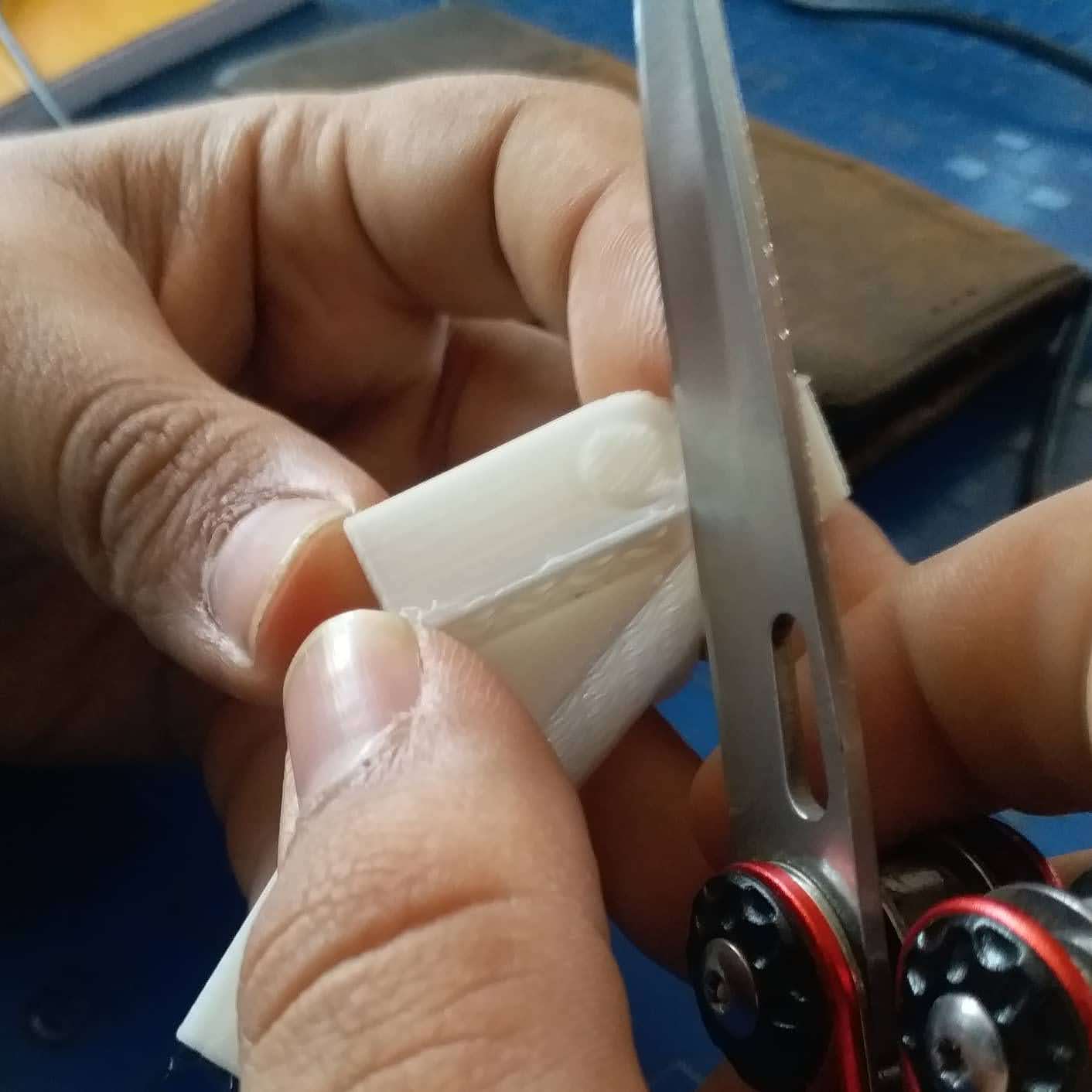
There was a bit of extra material at the bottom side of the model which I removed using a sharp knife's edge to run across the edge of the model, giving it a bit of a chamfer.
Here is the finished model:

I also tried a lil bit of stop motion animation with this one: