Wildcard week
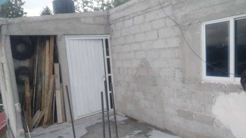
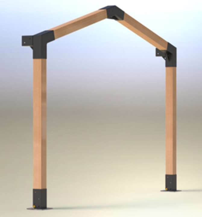
For this week assignment, I did not know what to do but later I remembered that I have a roofttop in my house that does not have a roof. One of my project for the summer is to put a roof on it, so I can go outside even when it raining. Thus, I will create the bases that I need to put to hold multiple wooden bars and create an structure outside and be able to put something over it.
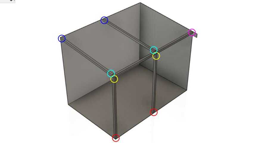
Thus, I started by doing an sketch and see what are the possible coneector that I might need. According to my first sketch, I will need 5 different connector to hold all the wodden bars as the following picture shows:
With this in mind and the possible connectors that I need, I proceed to do a benchmarking and think about what is the best option for my space.
Benchmarking
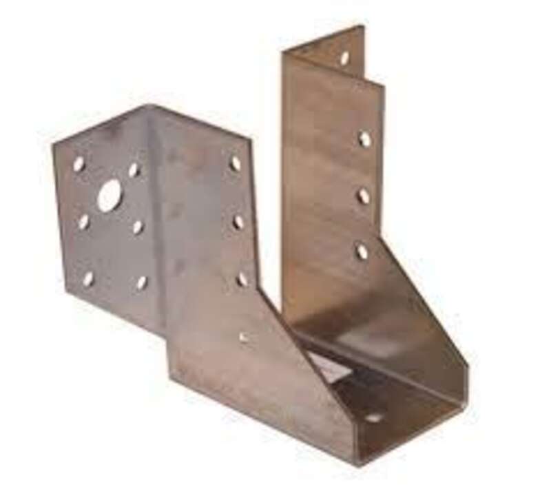
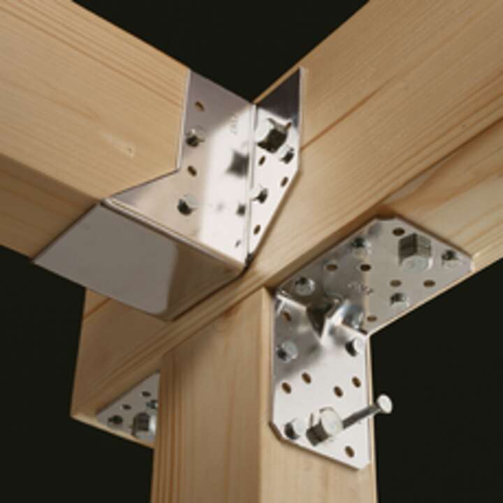
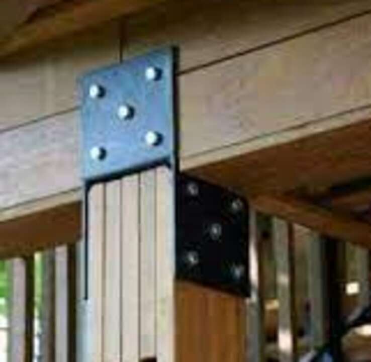
I have seen some rooftop before but I have never done it but I found many base holders and connector that can be used to hold and join multiple wooden bars. The most important that I found and the ones that are better as far as I can tell are the following:
Fiber Laser
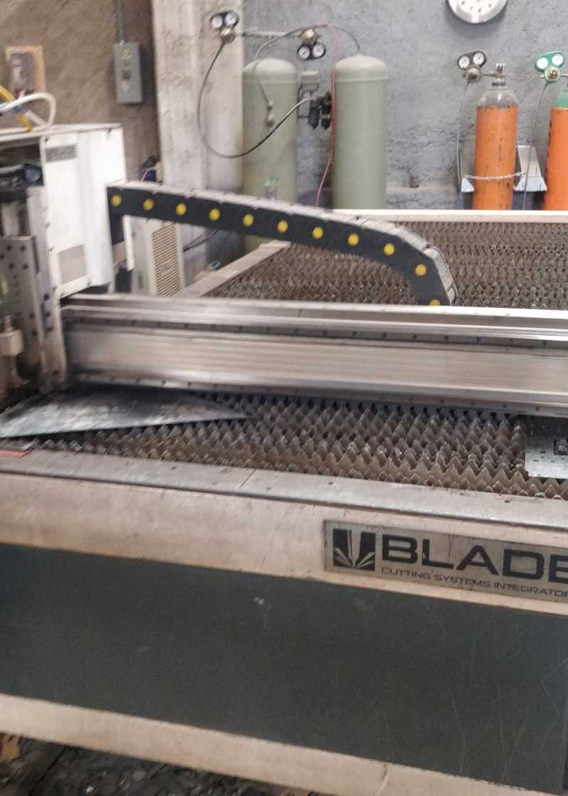
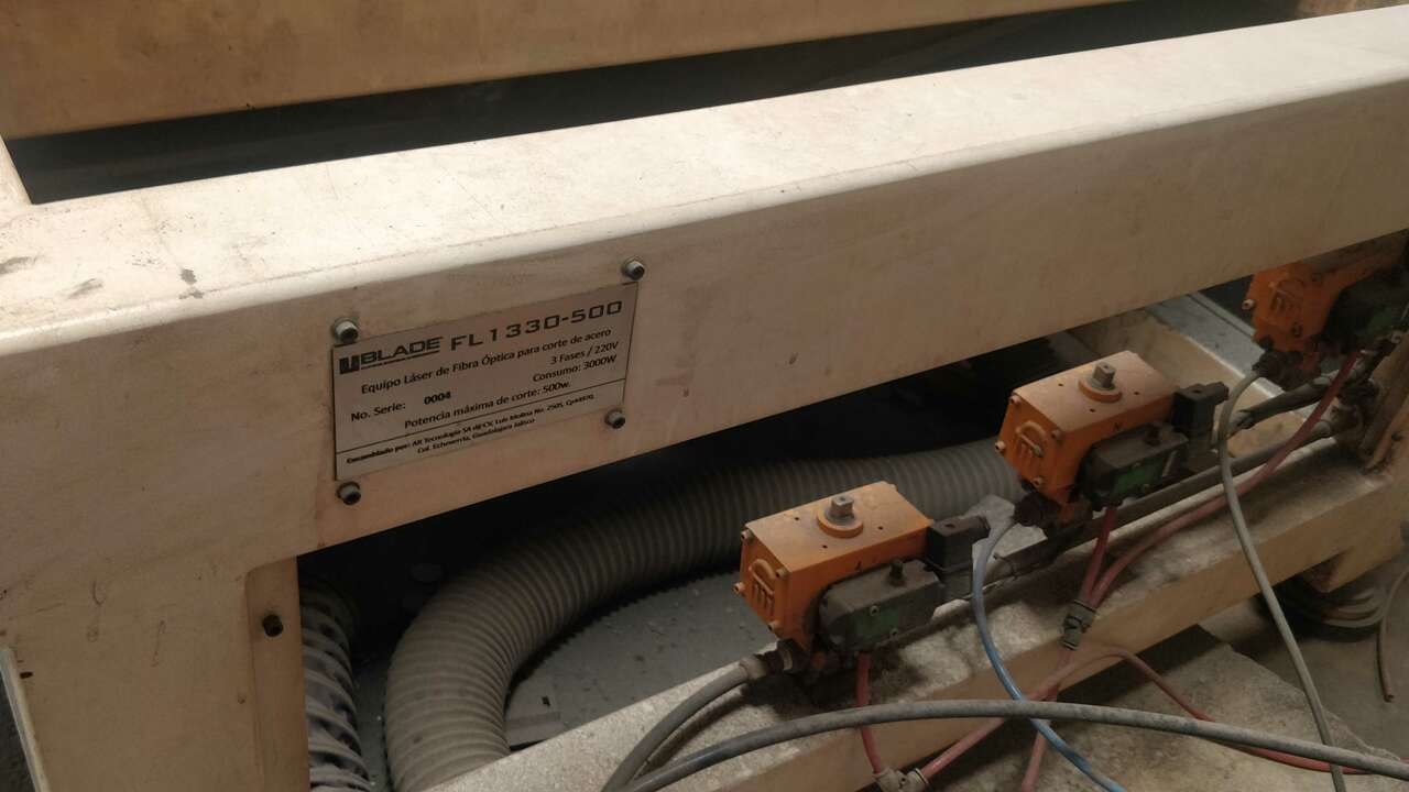
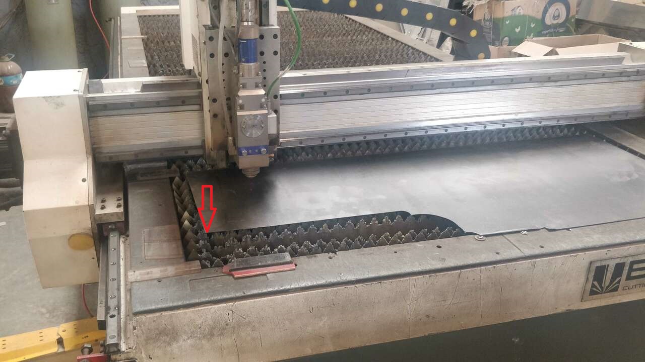
Since I created all the accesories with carbon steel, I used a fiber laser machine to cut everything. The model where I developed my practice is the FL1330-500 from Blade CSI. It is a really powerful machine because it has a laser power of 1000W. However, this machine was modified since originally it was of 500 W but they change the power source of the laser to provide more power. I love this type of machine because they can cut metal like if it is butter. The following picture shows the machine that I used.
The following table shows the main specifications of the machine:
| Characteristic | Value |
|---|---|
| Model | FL1330-500 |
| Working area | 1500 x 3050 mm |
| Laser power | 1000 W |
| Maximum cutting speed | 70000 mm/min |
| Software | CypCut |
The supplier provided us with the following list of materials that can be cut with this type of machine:
| Material | Cutting |
|---|---|
| Carbon Steel | |
| Copper and Brass | * |
| Stainless steel | |
| Aluminium | * |
| Titanium | |
| Glass | |
| Stone |
Designing
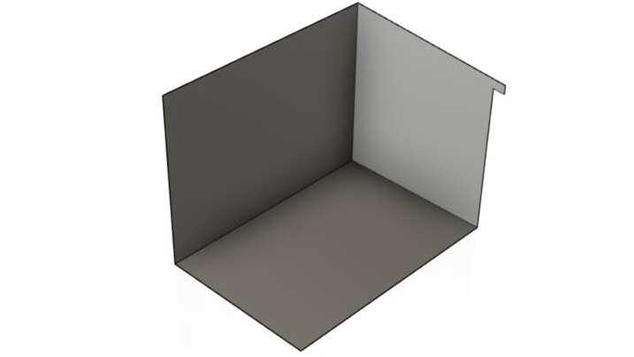
Now I have everything clear and I know exactly what I need. First, I will create the support that was in magenta color previously which I think is the easiest because it hold the wall with a perpendicular bar. So, all the angles will be at 90, well at least the angle to connect them.
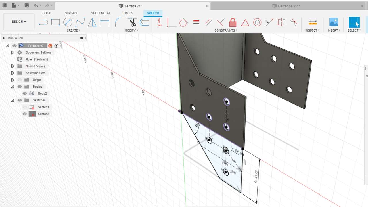
The most important in my design is that I used the sheet metal function to create all the supports since I will be using metal sheet of carbon steel to create the support. Thus, I create the first side of the support that is shown below.
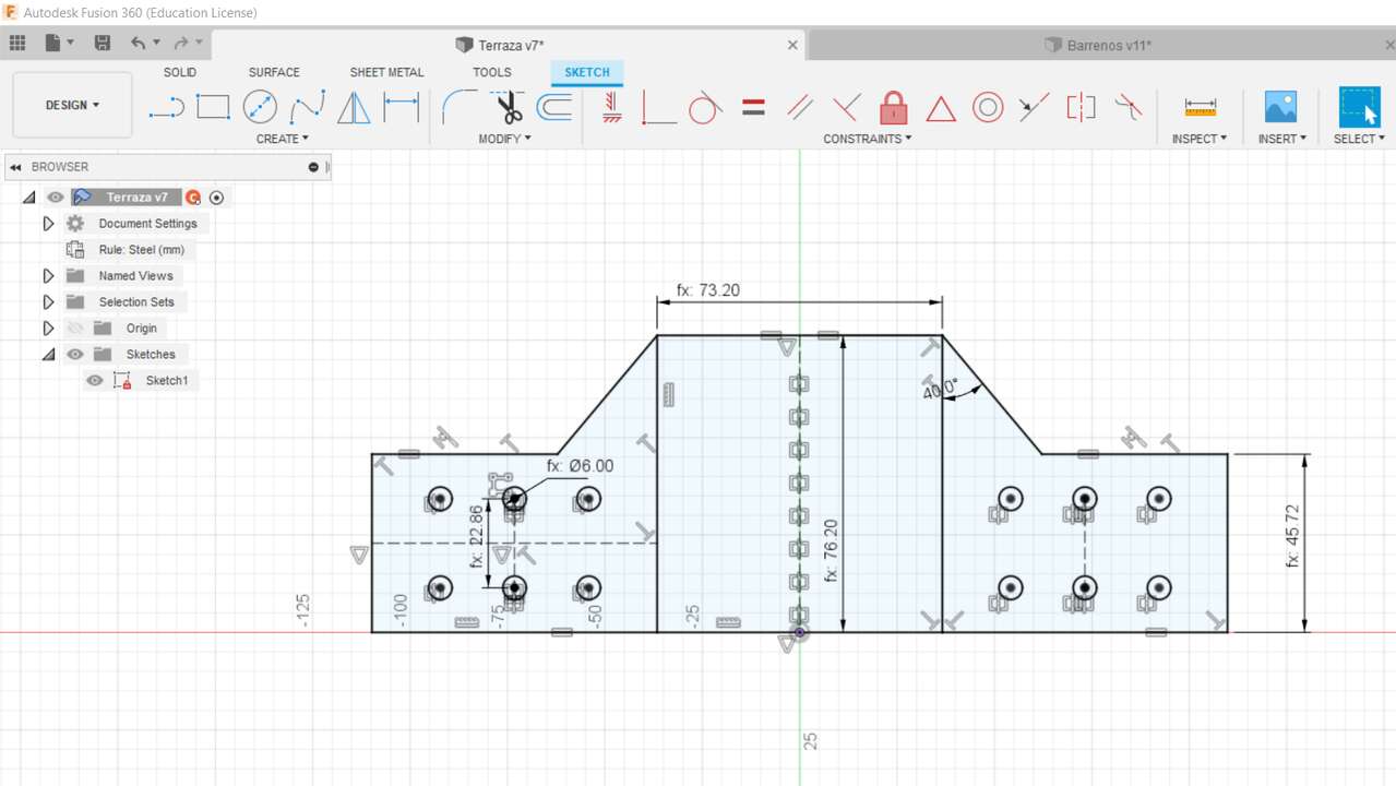
It is important to note that you must draw the line where you want to bend the sheet metal. Later, I used the sheet metal function that is on the top menus:
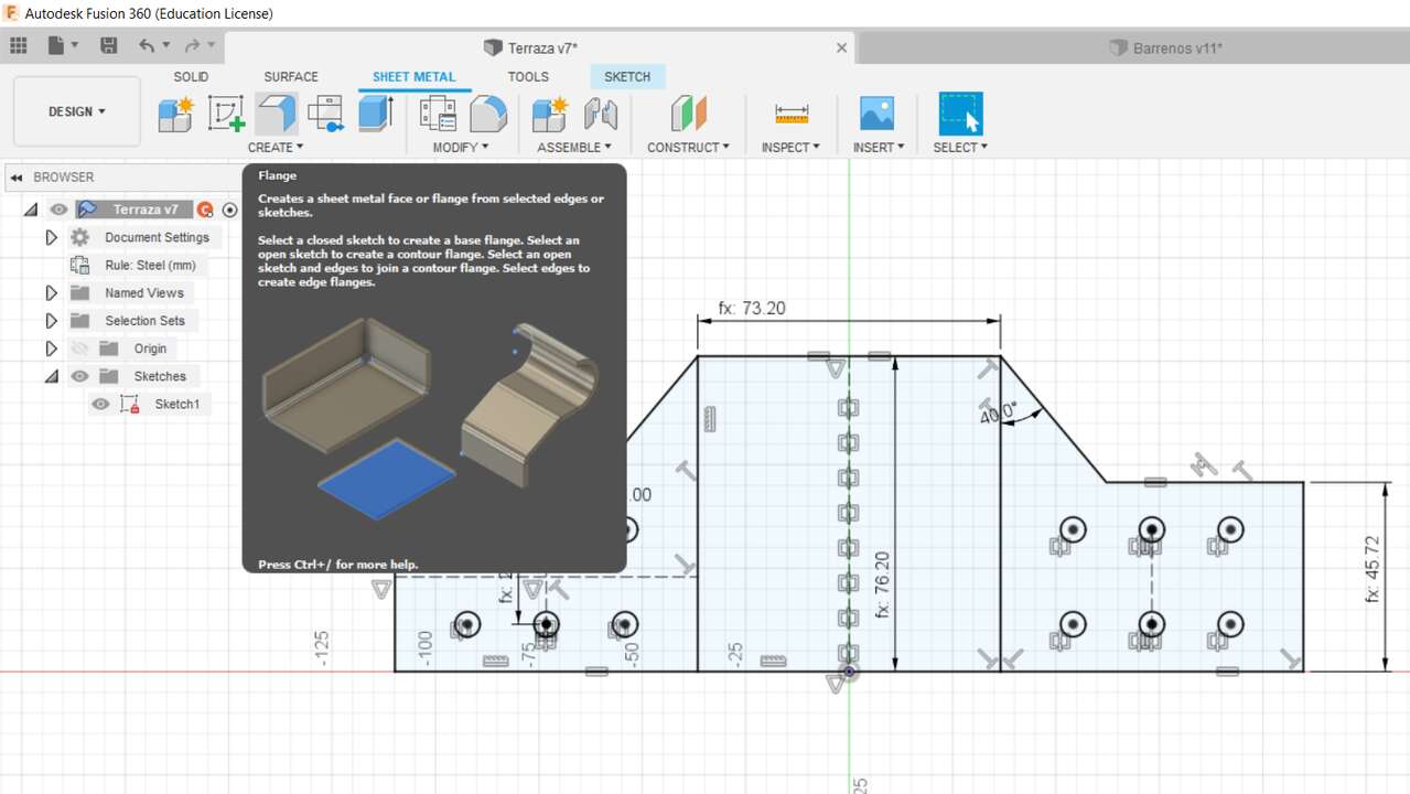
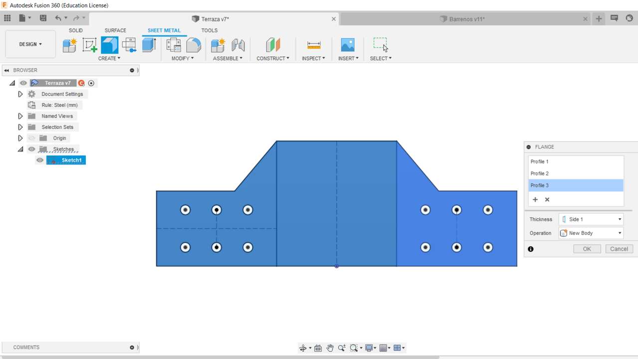
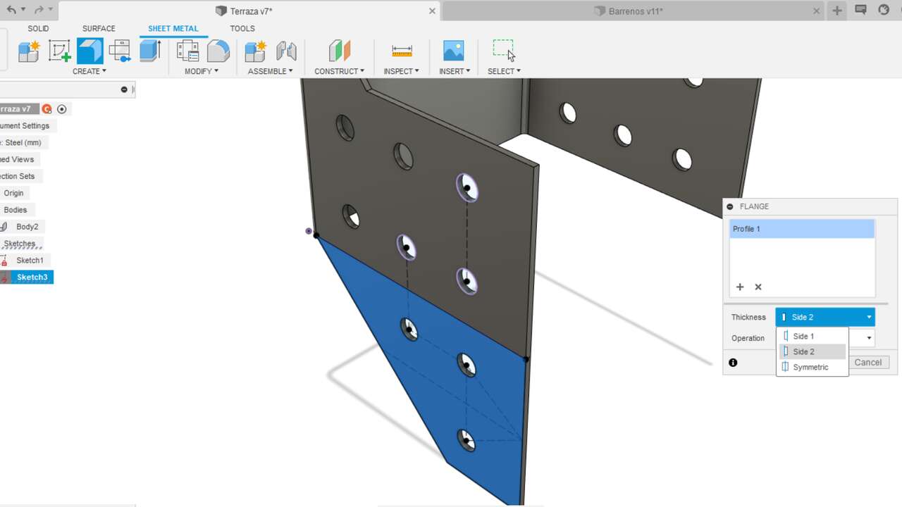
Once you found the option, a new window where you must select the profile will show up. It is important that you select everything and not just the part that will not be bended.
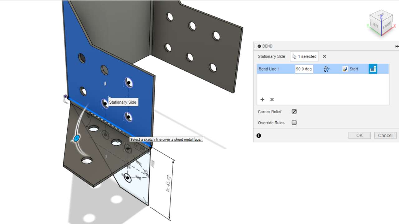
Now is time to bend the first part of the support, to do this. You must go to the sheet metal menu and select the bend function as the picture below shows:
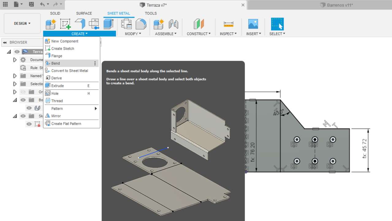
It is important to see that the sketch that was created is visible because it will be used for the bend function. So, after this function was selected, you must select first the part that will not be bended and later the part that will be bended as the image shows:
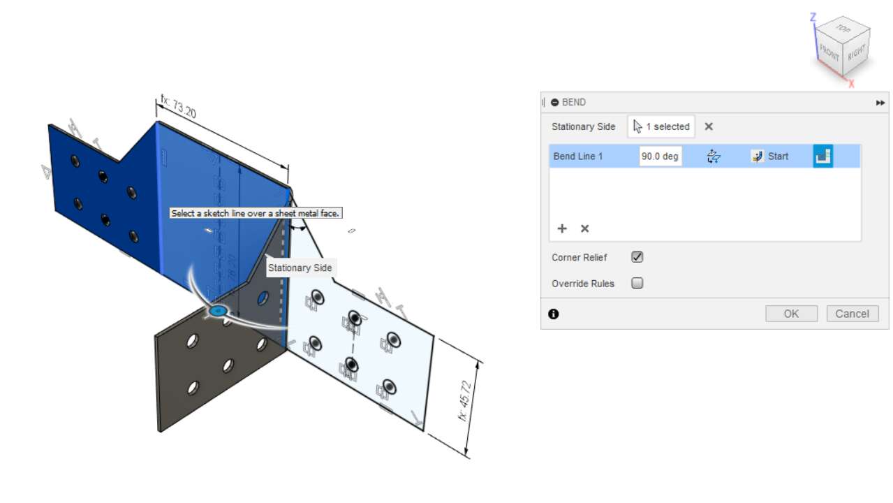
Make sure that "corner relief" in the previous window is selected. After this operation was executed, you must do the same but now selecting the other side that you want to bend. In case there and more parts to be bended, you must create new sketches over the surface that will not be bended anymore as the following picture shows.
And the same procedure must be executed in order to obtain the next bended parts. The only difference is that in the bend function mabe you must change the angle depending on the side of the base part you select.
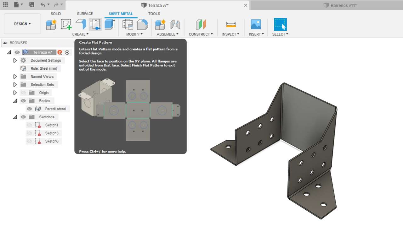
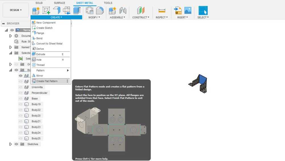
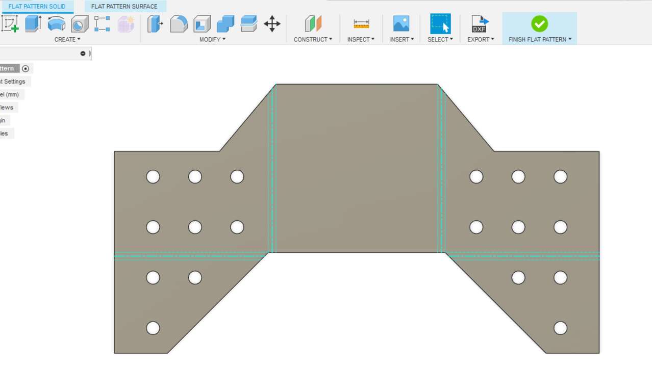
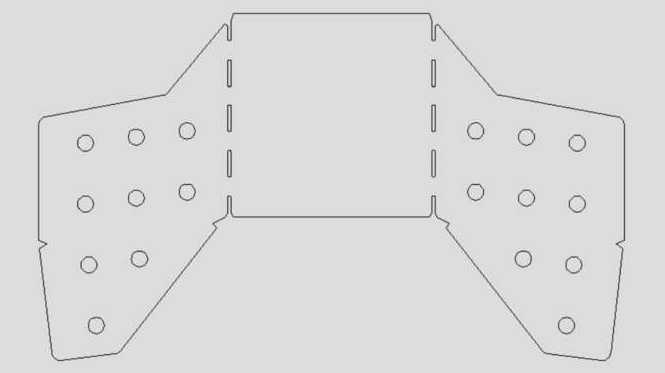
When the design is done, we can actually send create a vector file that show the outline with the centerlines necessary to make the bend afterwards. To do this, we can go to create flate pattern under the create menu, as the following picture shows:
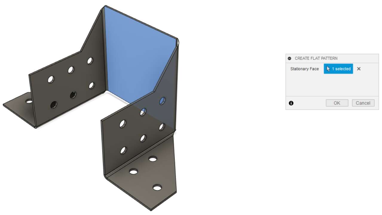
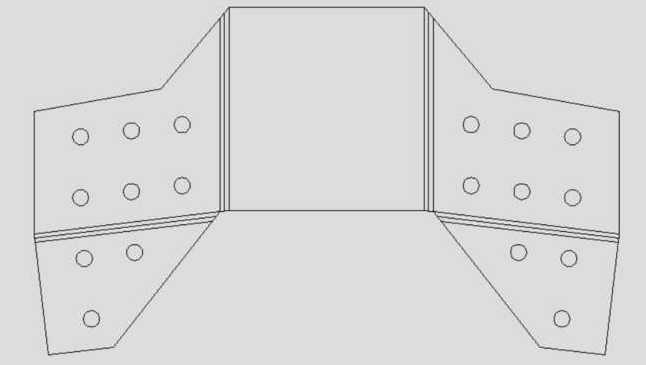
Later, we just need to select the face that will be the base, which in my case is the one in the middle. And later the figure will be unfolded as the second picture shows
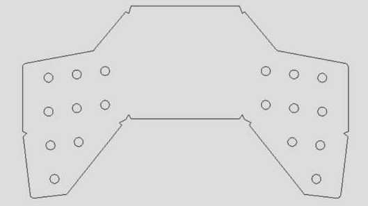
Finally we can save a dxf of the unfolded piece to cut it. Nevertheless, I was told to erase the middle line and create a triangular shape on the side where the materil will be folded as the second picture shows. This will allow me to use a bending machine and know where to put it on the machine.
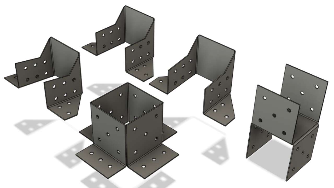
When I saw how process was working, I proceed to create the rest of the supports and they are shown below:
Cutting a test
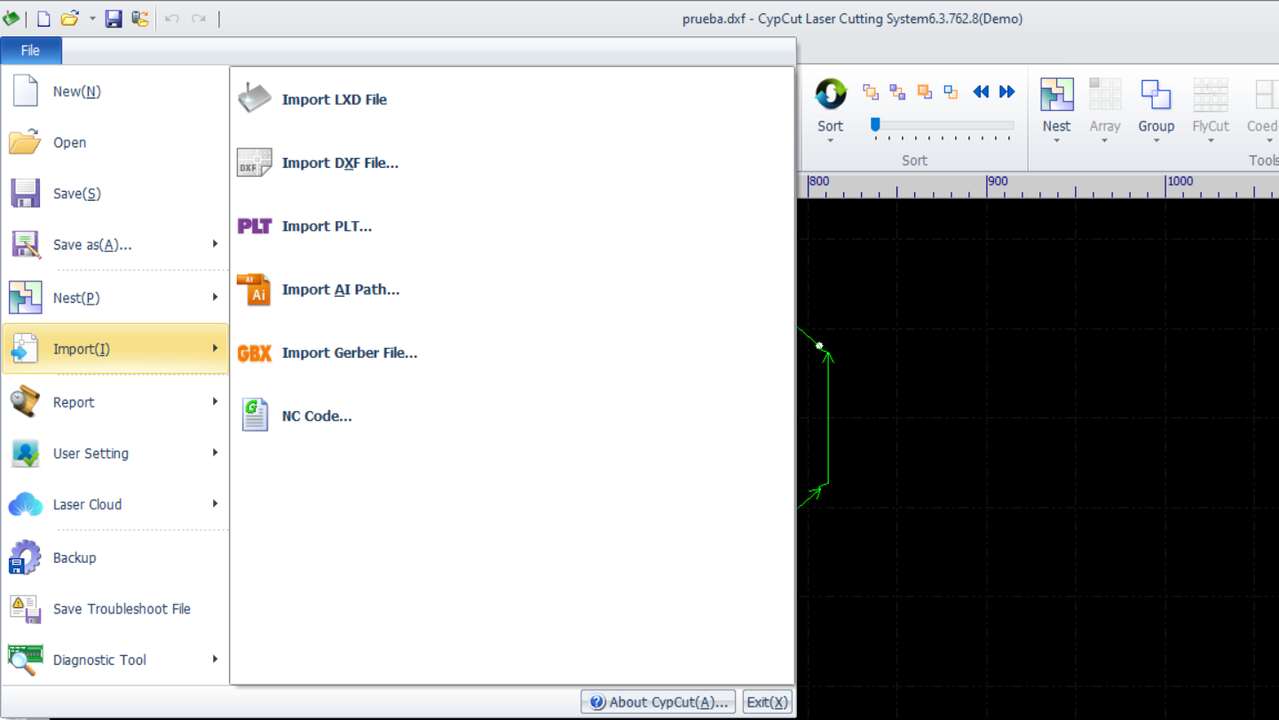
When we have the vector file with the required shape. We can send it to the program Cyp Cut just like the picture below show, basically we need to go fo file -> import and select the file to be imported.
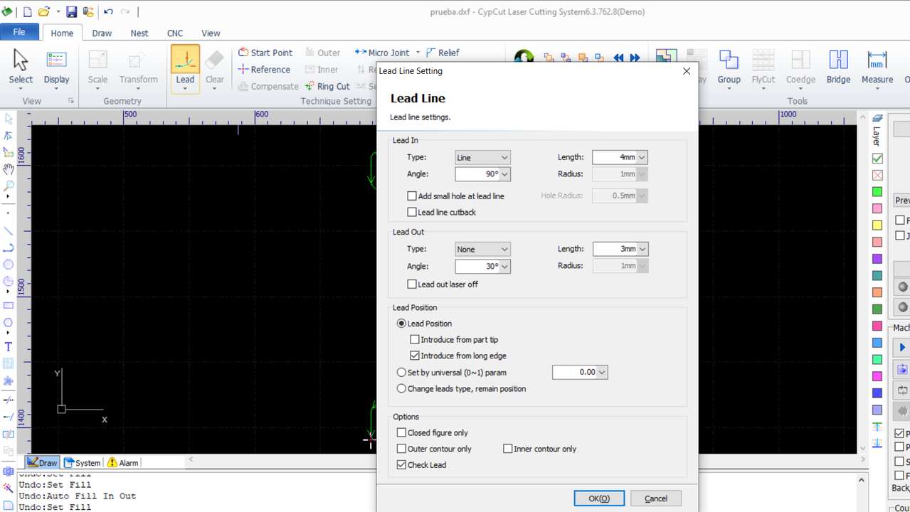
The next step, once the file was imported is to set the lead setting. These setting are really important because we need a lead in and sometimes a lead out when cuttin metal in the fiber laser machine to avoid that the laser burn or desintegrate some parts of the final part. The reason that the laser can generate this finish in case we do not use lead is because the power that we use to cut through the material is much bigger than the one we need after the laser already went through. So, the setting that I used to cut my pieces are the following:
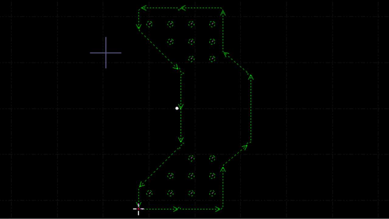
The next picture shows how the lead are placed after we click in the Ok button. The white lines represent the lead in and out while the green lines represent the cutting lines where the fiber laser will cut to get the final piece.
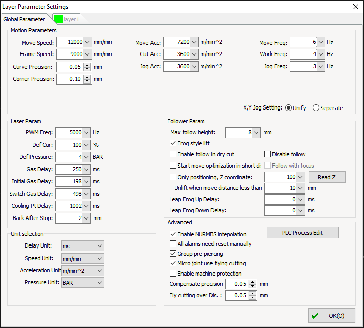
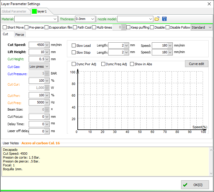
Now, we have to select the parameter to cut the material, in my case I will cut carbon steel. To access to these parameter, you can simply click on the Layer button that is on the left side of the window. Since, it is a machine really complex I used the parameters that they have to cut this type of material and those setting are shown below:
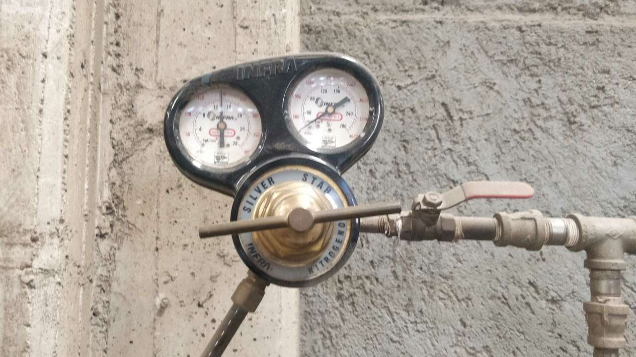
We are almost set to send the first cut, but first we need to activate the oxygen that we will be using. A fiber laser machine needs oxygen or nitrogen to cut. Usually the oxygen is used to cut carbon steel, the onyly problem is that the side where is cut it looks a little bit black but it does not hange nothing to me. Thus, I will use oxygen with a pressure of 14 kgf/cm2 as the picture above shows. Another aspect is that the machine uses valves to activate and deactivate the oxygen dependign on the funciton that the machien is doing.
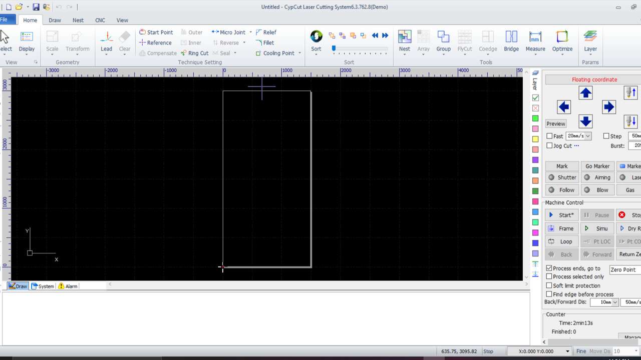
The material must be placed and the laser must be moved to the bottom left corner of the material to start the program in that point. The next picture show the mateiral over tha mchine and the place where the header must be placed.
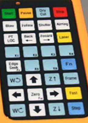
The next steps are done in the control:
- Click on Shuter to active a red light to see more precisly where the header points
- Move the header with the arrows unitl you reach the bottom-left corner
- Click again Shuter to deactivate the red light
- Click on the Start button
- Enjoy watching the laser while it cuts
I recorded a video that show the fiber laser cutting:
Bending Process
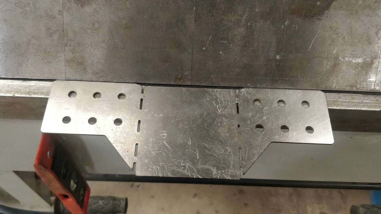
I did not know how the process can be done but I did the first bend of the center. The problem was that I was only able to cut one side because I did not have space to hold one the piece and make the other side resulting in a failure while cutting.
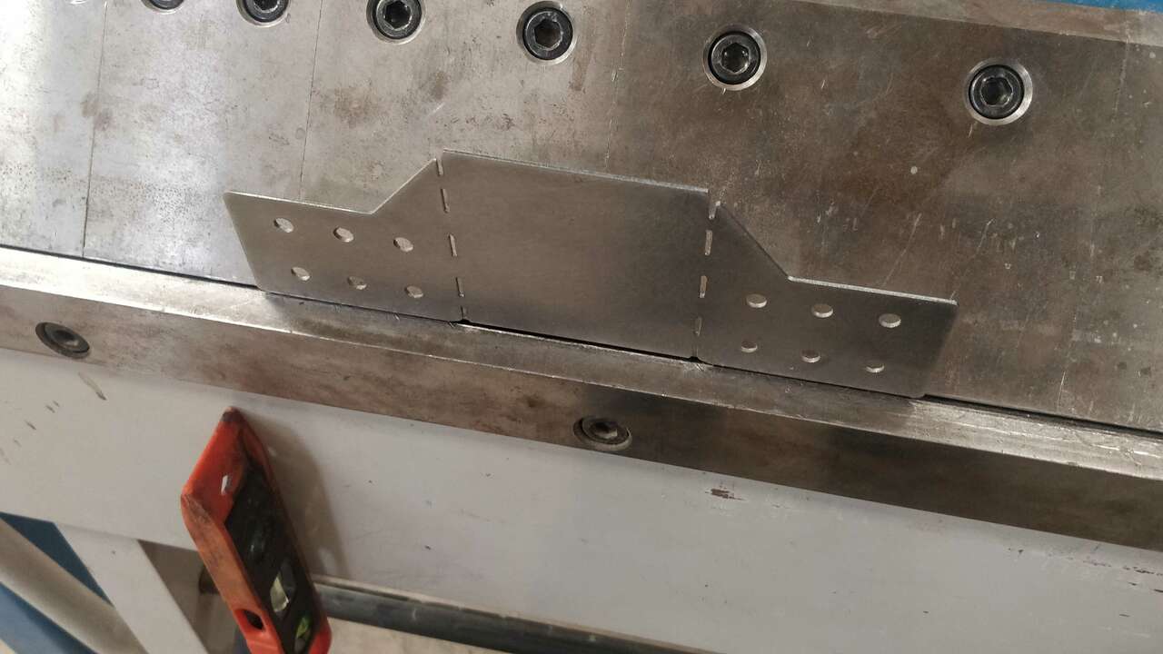
A recommendation that was given to be was to create slots where the materil must be bended to be able to bend it almost with the hand and avoid using the bending machine for evertyhing. So, I went back to the design and I added the slots in the design as the followign picture shows:
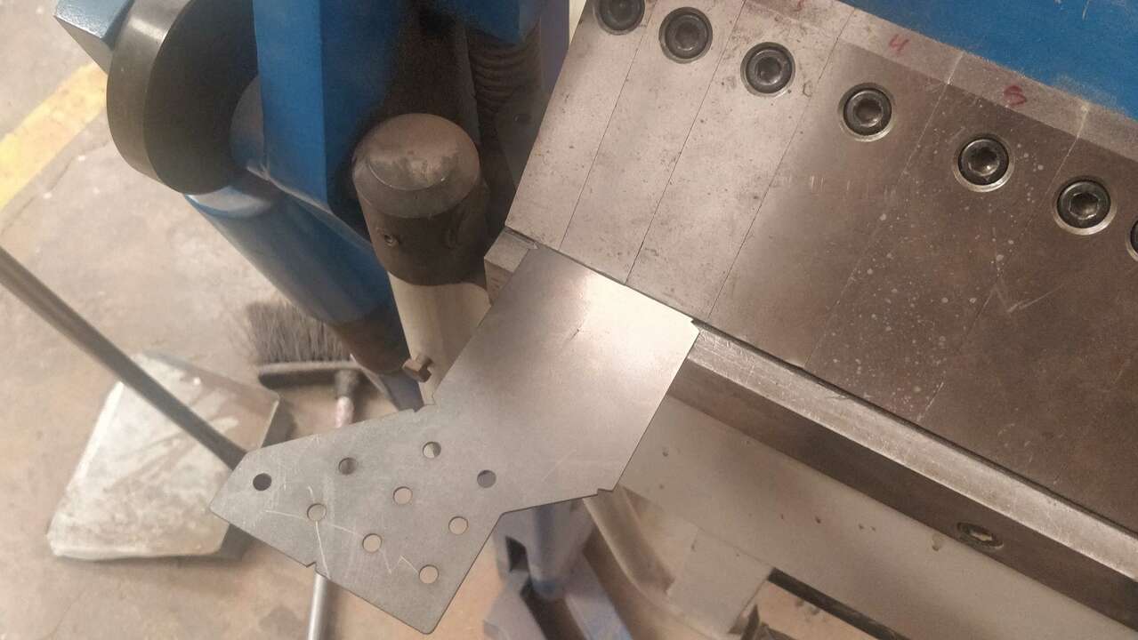
With the second piece, I cahnge the bendign process to bend the smallest parts first with the bending machine because that where there are no slots and where I need the bending machine.
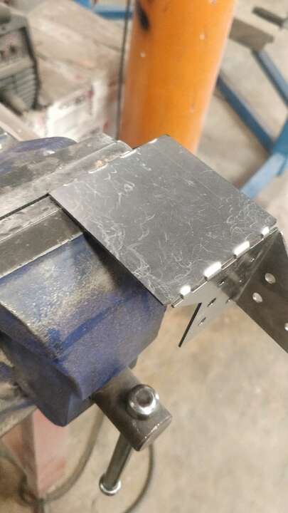
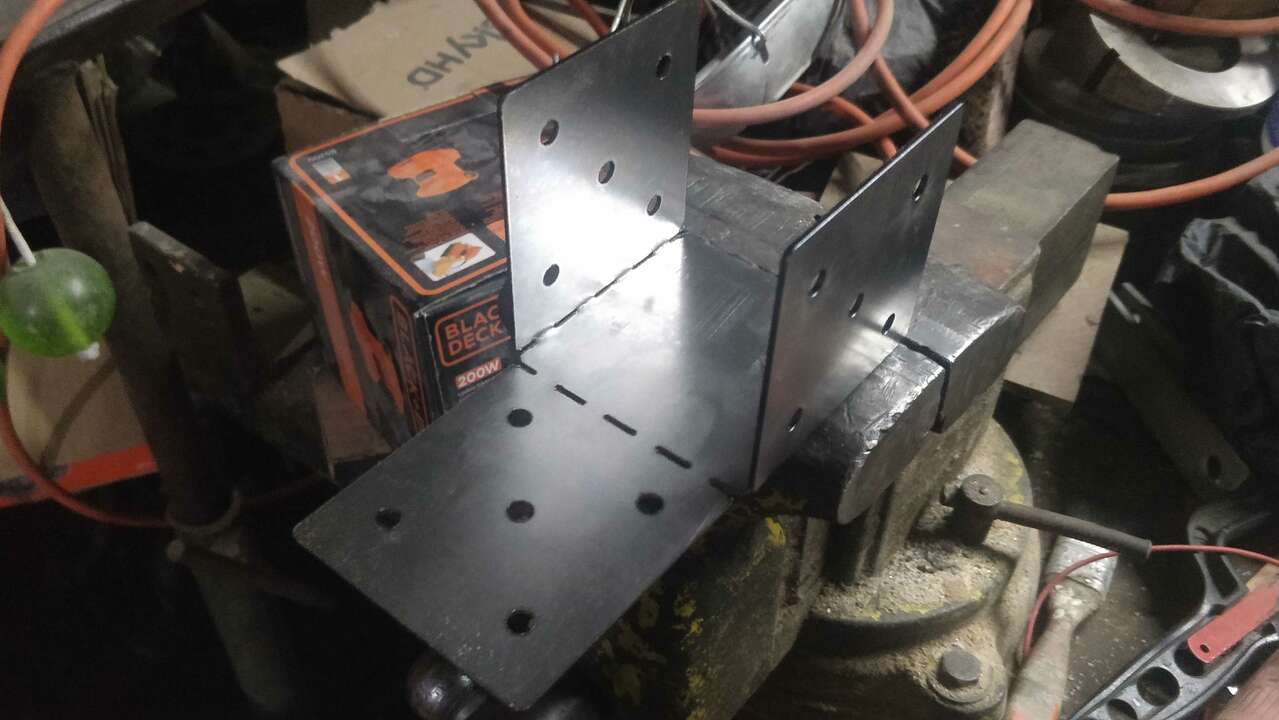
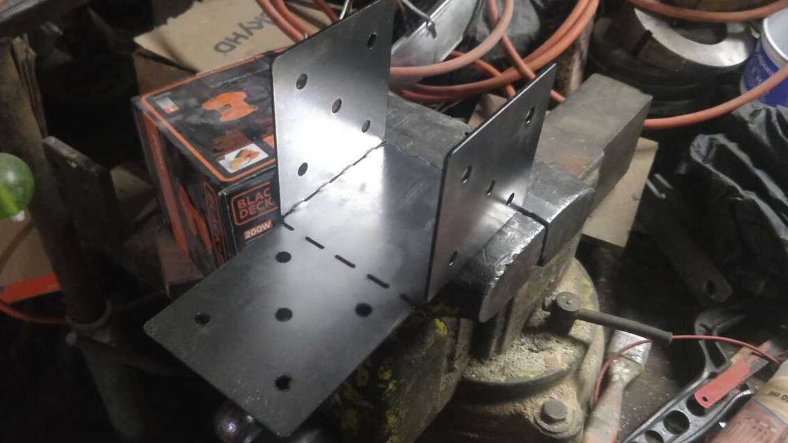
For the bends in the center, I went to a bench vise to hold the sides of the piece and later I used my hand to bend the center as the pictures shows. When the first bend was donde I change the piece to the other side and I did the same
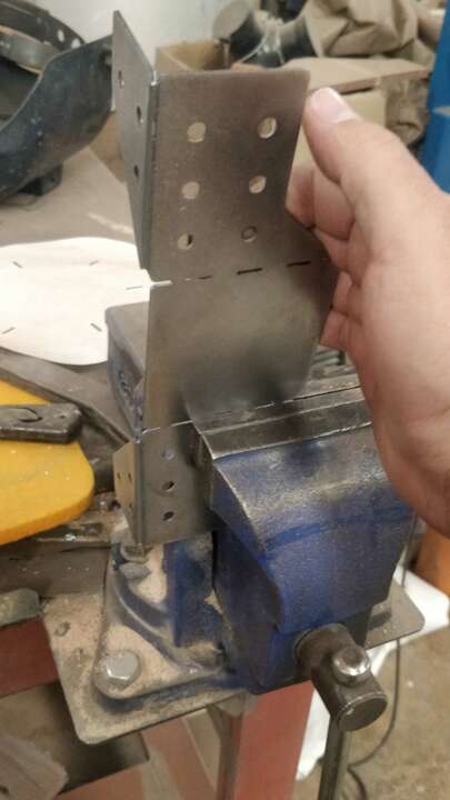
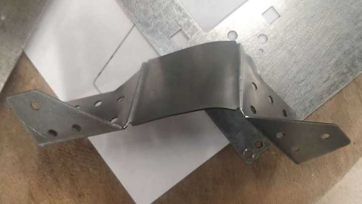
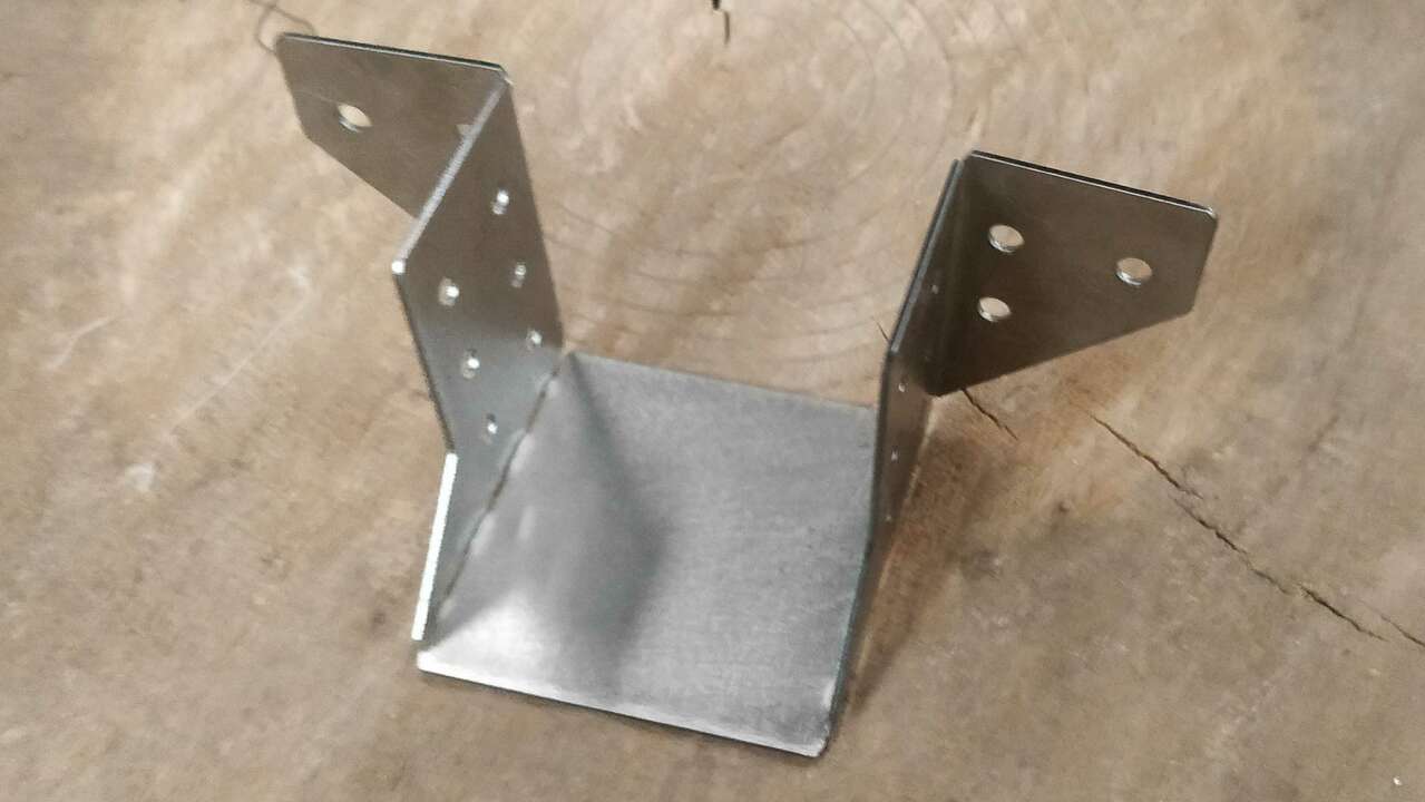
The second try looks really solid and good.
Making the rest of the parts
Knowing the proces and how the design must be done, I modified all the files and send the rest of the parts to be cut on the cutting fiber laser machine. And of course I reacorded a small clip when the process was being executed.
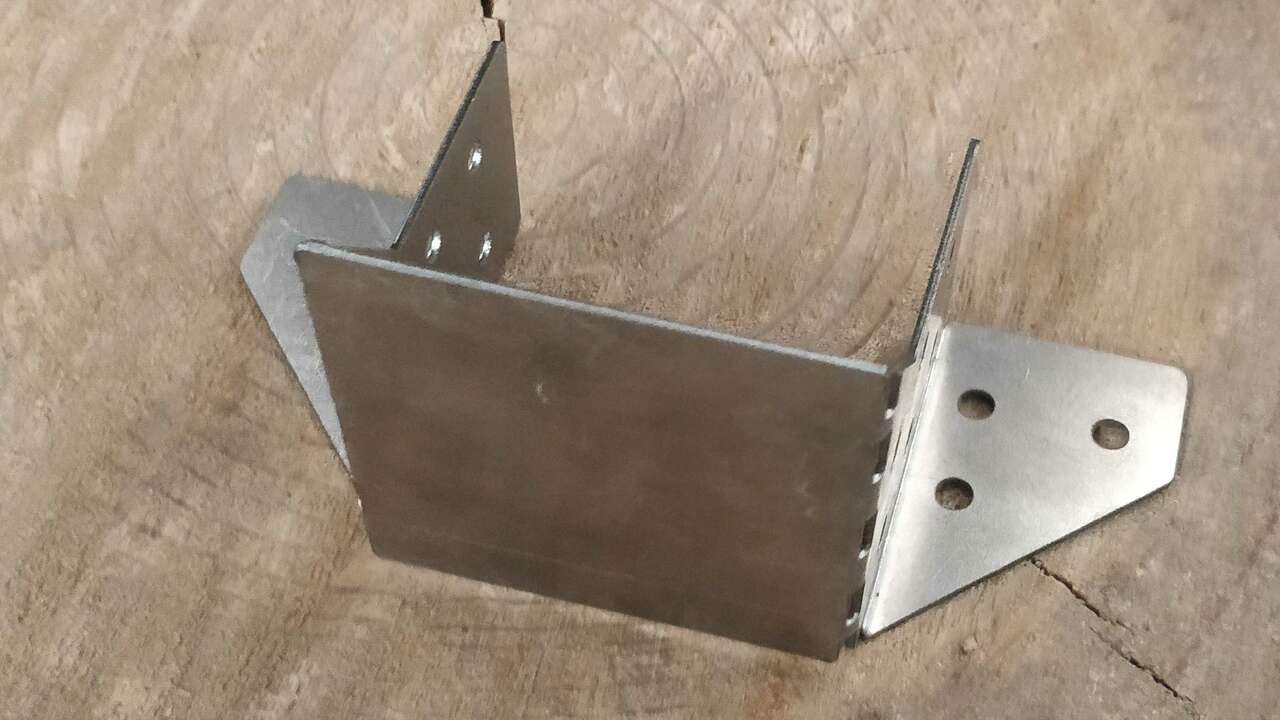
I was not able to bend all the parts at the Fablab but I have a bench vise and I finish the bending process in my house. The next pictures show another piece while it is beign bended.
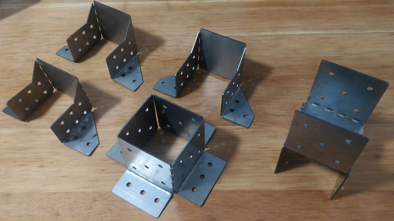
Finally, the next picture shows every single support that was made. I fell really happy to see that everything that I planned worked at the end. When I put the support in my rooftop I will put the pictures of the support placed whee they must go.
Files created
Useful Resources