Hello again, good to see you here again, this week has been a lot of fun for me since we had to see PCB design (you can see a little more of me here), with electronic design I have a love-hate relationship and you may wonder "Why ?! If you are an engineer", what happens with circuits is that designing them is beautiful, but soldering them is an ordeal and on the other hand we have the faults that we have along the way that are not one or two (there were 6 in my case), however out of all that, seeing the result and above all seeing that blessed LED turn on when connecting it, is a satisfaction that has no description.
The week that passed, when reviewing the web pages, Benito gave me a golden advice, he said something like: “An assignment should be like a food recipe”, immediately a light illuminated me and that is why today I bring an exquisite recipe for an "Attiny USB Programmer".
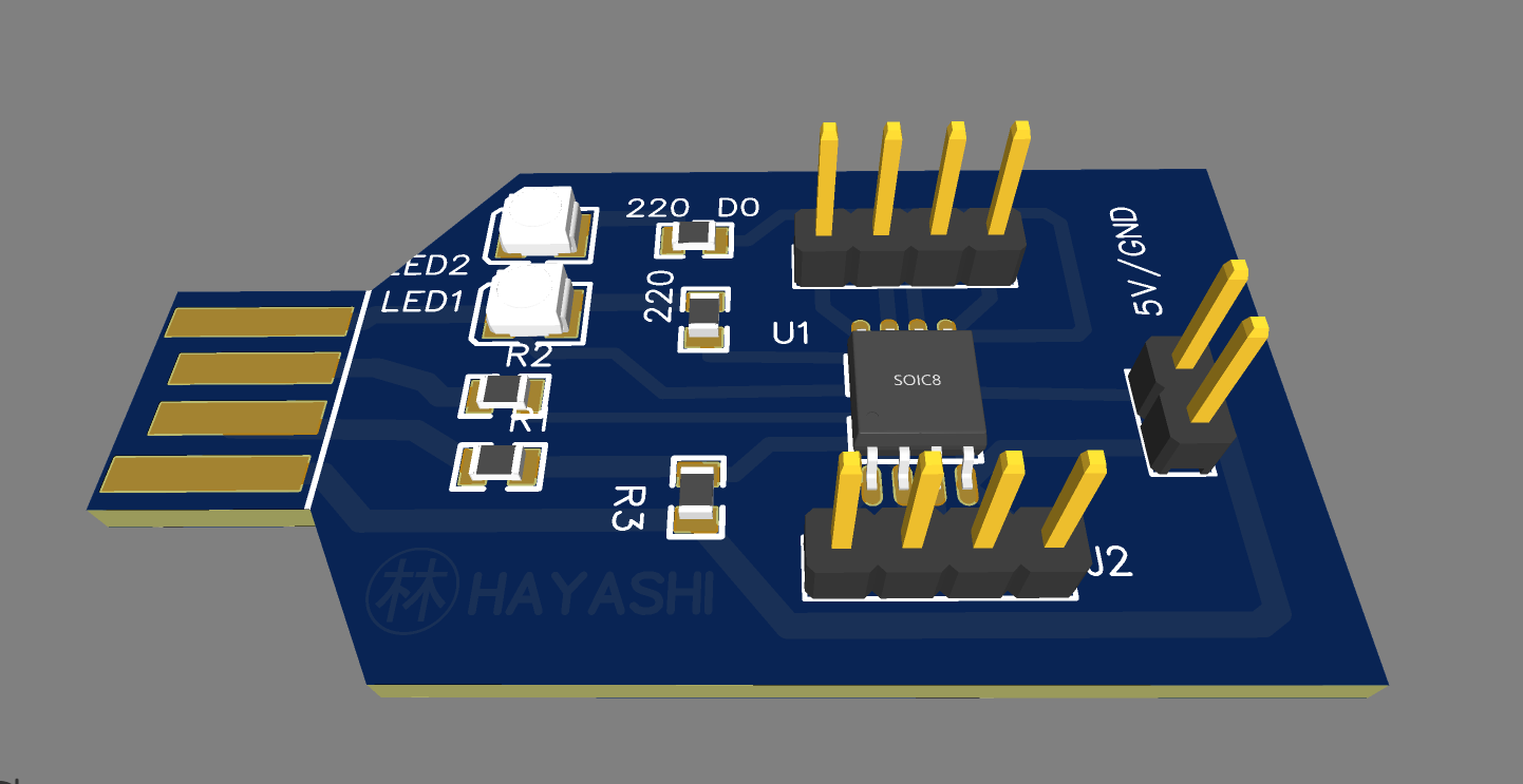
The dish to prepare is an electronic card which will allow us to program a microcontroller (Attiny85) with the least amount of components and steps, something simple but effective.
This programmer, unlike others, only requires 4 pins to be programmed (VCC, GND, D +, D-) unlike others that require an integrated serial to communicate with the computer port. Another quality of this card is its versatility since the diversity of components that can be used is enormous. Finally, if you are interested in making an electronic card compatible with Arduino and at a very low cost, do not miss the following steps.
The ingredients
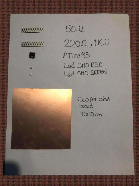
For this programmer we will need the following ingredients:
a)Resistors
The resistors are a very important component, especially those that are connected (R1 and R2) directly to the data bus (D +, D-) of 50 ohms (this value can vary between 50 to 100 ohms approx) these guarantee continuity serial transmission between our PC and the microcontroller, on the other hand we have the resistors found in the LEDs (Power and D1). Remember that the main function of a resistor is to oppose the passage of current, therefore it serves as a protector in the case of LEDs and in the case of the data bus as a voltage divider to guarantee a voltage threshold.
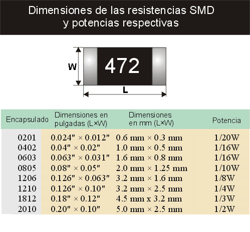
The resistors that we will use are SMD (Surface mount device) resistors, since they have reduced dimensions and this will also help to avoid parasitic currents (smaller contact area on the board = less noise). The resistor packaging that we are using is 1206 because they were the only ones that were achieved.
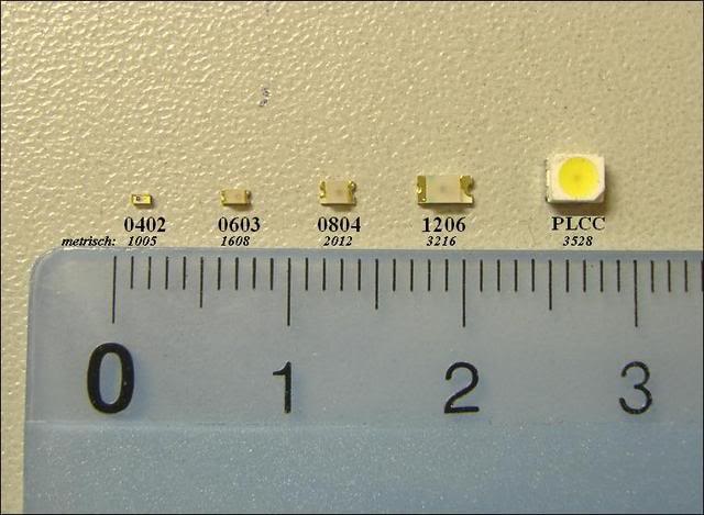
SMD resistors have different types of packaging and this is due to the dimensions they have, this is reflected in the following image:
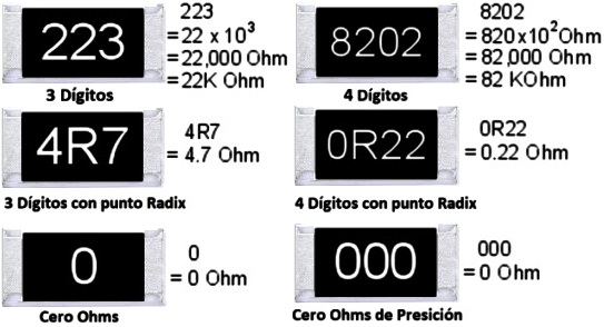
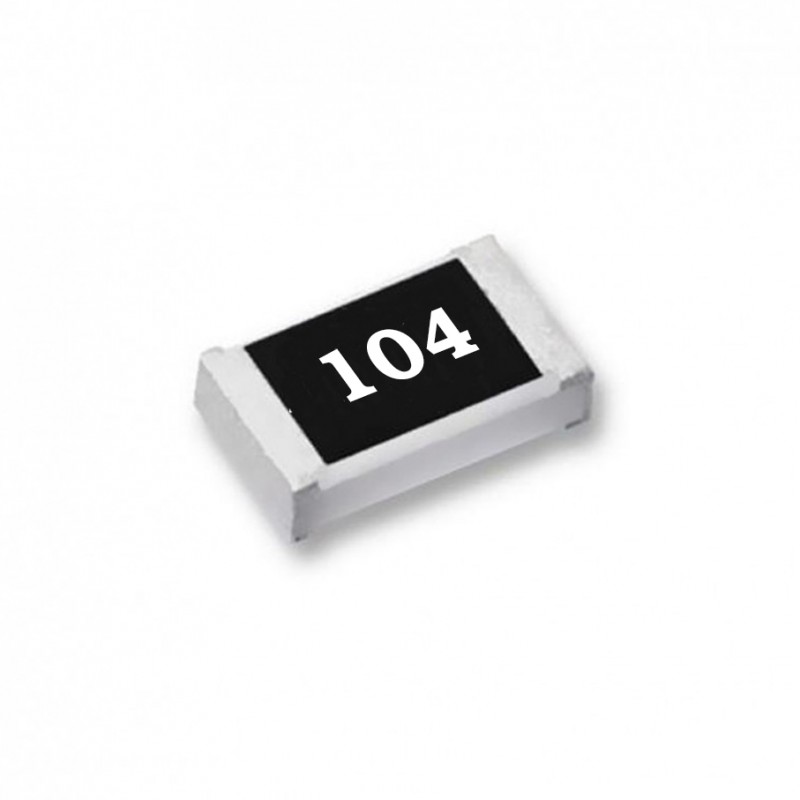
These resistors also have a very particular way of finding the values (ohms) they have, unlike the others that have a color code, they have a numerical code that can be interpreted as follows:
As you can see, the last digit of each resistor is a power of 10 that must be multiplied by the preceding digits. Based on the above, do you dare to calculate what the value of the next resistor would be? .
Chef's Notes:
-Did you know that there are 0 ohm resistors?
Imagine 2 cities separated by a river, the only way to connect would be above it, right? , the 0 ohm resistors fulfill the same function, they are bridges between 2 copper tracks that are separated by another copper track.
-Do you need help calculating values in SMD resistors? Click here.
b)Led
LED is a light emitting diode, whose main function is to allow the passage of electric current in only one direction and to emit a light when the current passes. In our circuit we will use it with signals and we will have 2:
-Red power LED: This LED is connected directly to a resistance, 5V and GND of the microcontroller. Its function is to show us that our electronic board is well powered.
-Green LED: This LED is connected to pin number 5 of our microcontrollers and will basically serve as a test before a first programming that is done in our programmer (like the popular Blynk).
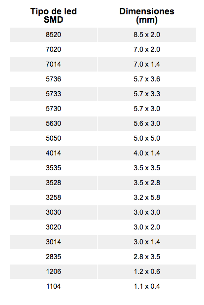
In our case, the 3528 package will be used, which has dimensions 3.5 x 2.8 mm.
c)Microcontroller
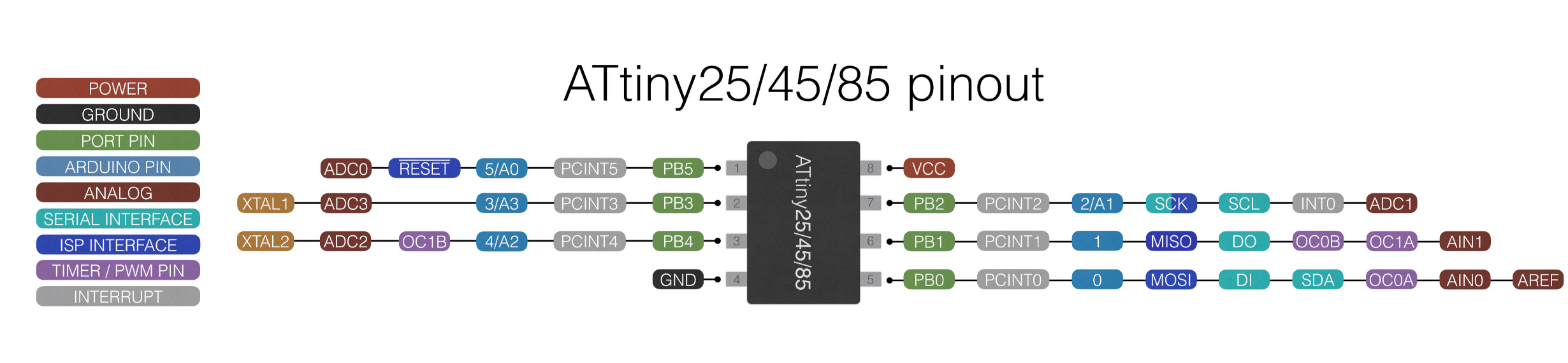
And like a meat on the grill or a good sole in the ceviche, we have our main actor here (apart from the chef), the attiny85 is a microcontroller from the 8-bit AVR series from Atmel (here we can also find his brothers ATtiny25 / V / ATtiny45 / V) This microcontroller was chosen for its practicality at the time of being prototyped and for the minimum number of components you need to build a programmer circuit with it (as you can see in the image below).
The Attiny85 has a minimum number of pins (legs), however they all share more than one function that can be activated through lines of code, these are the functions of its pins:
All these references regarding the attiny can be found in its datasheet
Finally, this attiny was chosen among many because it is compatible with the arduino software (arduino IDE) and will serve us later for other projects, thanks to its friendly interface.
Chef's Notes:
-Microcontrollers are a fundamental part of a programmer, therefore I recommend that you research a lot about them before acquiring one and above all that you use those that you can find replacement in electronic stores in your country.
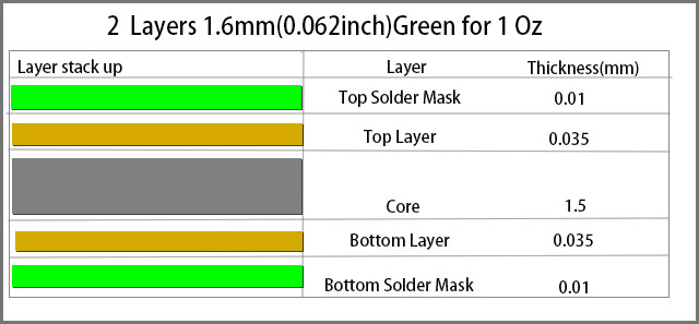
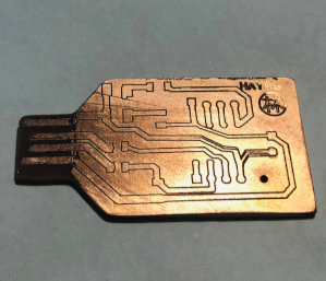
d)Copper clad board
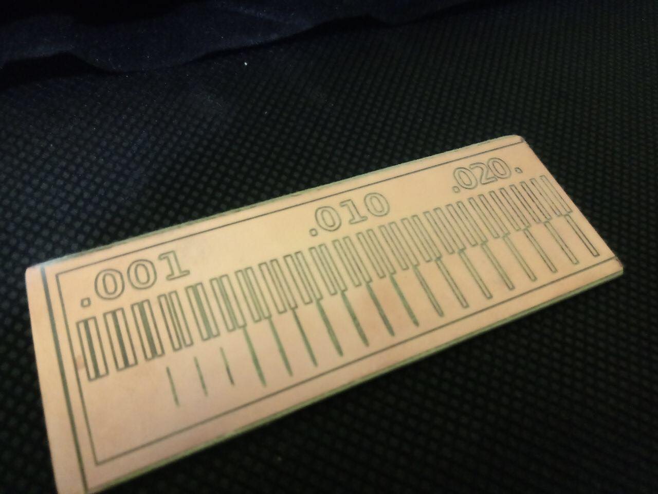
To finish naming our ingredients we have the base of everything, which will support all the aforementioned components, so it is very important that it is resistant and made of a good material. On this occasion, the stock of the local market is used, which did not give the only option to phenolic plates covered with a copper sheet, which is not a bad option but they do have a very limited copper layer as can be appreciate in the following image:
The preparation
Once all the ingredients are known, it is time to prepare this low-price programmer with the attiny85, for this you must follow the following steps:
a)Step 1
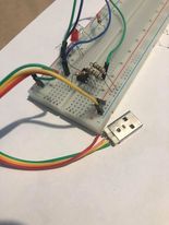
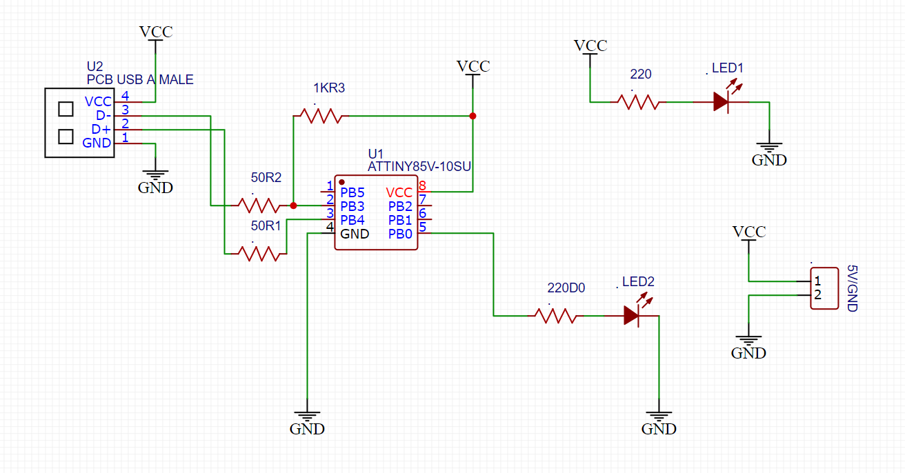
I always indicate that before even daring to solder or cut something, you must design and test your circuit, this implies that you do a simulation or that you assemble the same circuit on a breadboard and check that it works correctly.This step is one of the most difficult since it is making a complete circuit on a breadboard and it is very tedious to wire but it will save us a lot of time by not having future errors due to a wrong component purchased or a poorly made circuit.
b)Step 2
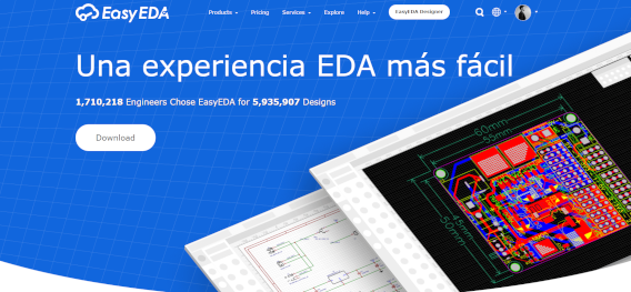
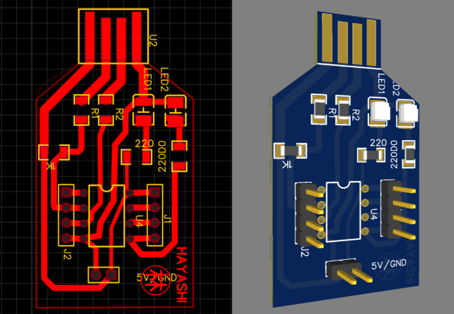
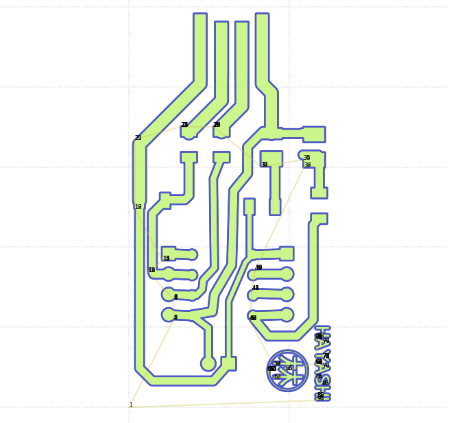
When you have verified that the circuit you want to implement in the pcb works, it is time to create the tracks that our CNC machine will then make, for this it is necessary to have an electronic design program, in this case it will work with easyeda (https: / /easyeda.com/)for its very user friendly platform and its diverse library of components available to it.
Easyeda has a completely online interface (although it also has an offline option) which allows us to: design, simulate, export, view in 3d, etc. In this interface we will make the circuit in your designer and then we will transform this circuit into tracks for the PCB.
Once these tracks have been designed, we can only export them in Gerber format for their manufacture.
Chef's Notes:
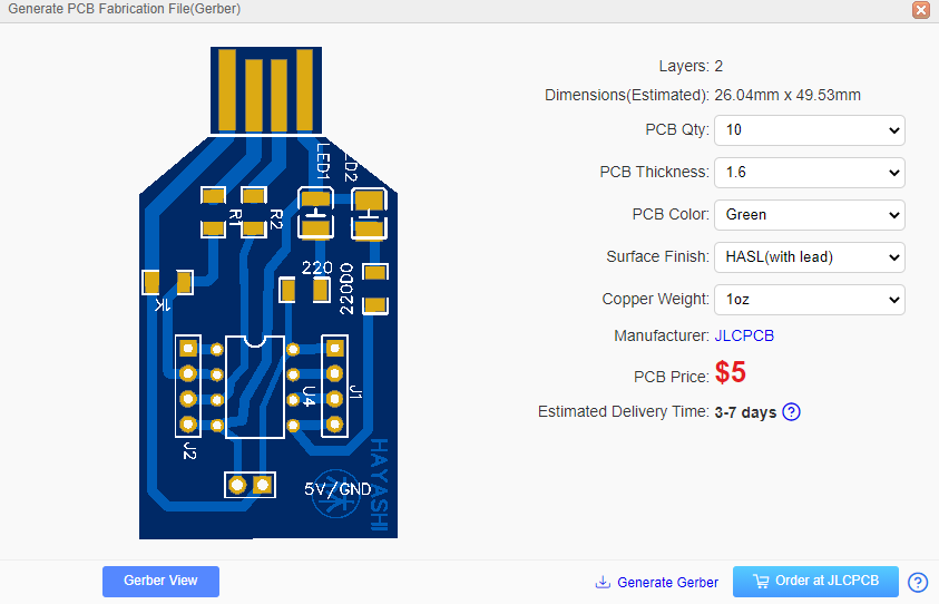
-Easyeda also allows us to quote the components and plates that we are exporting, in this way we can think about manufacturing plates for all our projects and give it a more professional finish.
c)Step 3
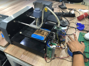
We reached the decisive part of this mission, which personally brought me nightmares for a few days. This step 3 is to send the file to the CNC machine so that this sentence is placed on the phenolic plate and we obtain the desired circuit, but what happens to the machine cnc is faulty ?.
Time was playing against us and we had to solve, I made the decision to repair it, but before I comment on how I did it, I would like you to know a little more about this CNC machine:
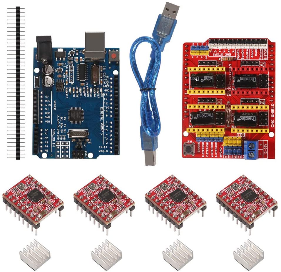
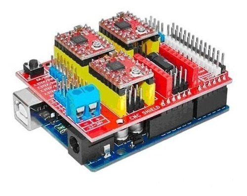
-Modela MDX 20: This machine was recovered by Alexandra and I, from the Spanish cultural center which had it as a museum piece (an MIT machine did not deserve to end like this), when I opened it the first time a couple of years ago, With the surprise that the hardware had been changed for a private one, which greatly limited the ability to make modifications to the machine, that is why I decided to remove it and replace it with an Arduino-based system and a cnc shield.
Once assembled, the equipment was not used again until today, it was there when I realized that it took many that just change the hardware, it also required new software.
* The a4988 modules, for this I leave you here a collection of videos to be able to calibrate them perfectly thanks to the "elprofegarcia" channel.
GRBL
The new update of GRBL 1.1 was used for the software.
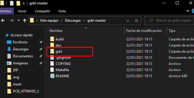
-Download the zip file and unzip it, from this folder we will copy the folder called “grbl”.
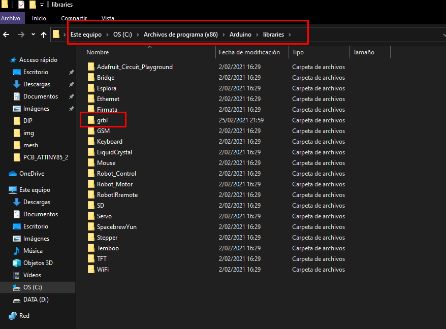
-Then we copy this folder in the libraries folder inside the folder where arduino ide is installed (you can download arduino from here).
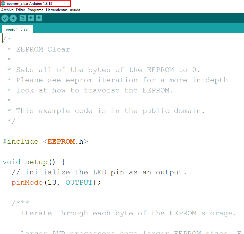
-Now it's time to burn the file (stop there !, leave that lighter, I do not mean that way of burning), for this we go to the Arduino IDE and we must load the following example program:
-The Eeprom_clear example (file / examples / eeprom / eeprom_clear) will allow us to delete any program that is inside our arduino.
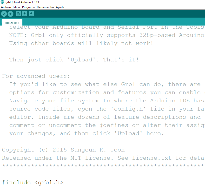
-Now it is the turn of the GRBL (file / examples / grbl / grblUpload), you must upload it to your arduino.
Chef's Notes:
-Don't worry if you get a warning message about the percentage of memory used by this program, grbl is usually a very heavy program and requires more than 90% of the capacity of your arduino.
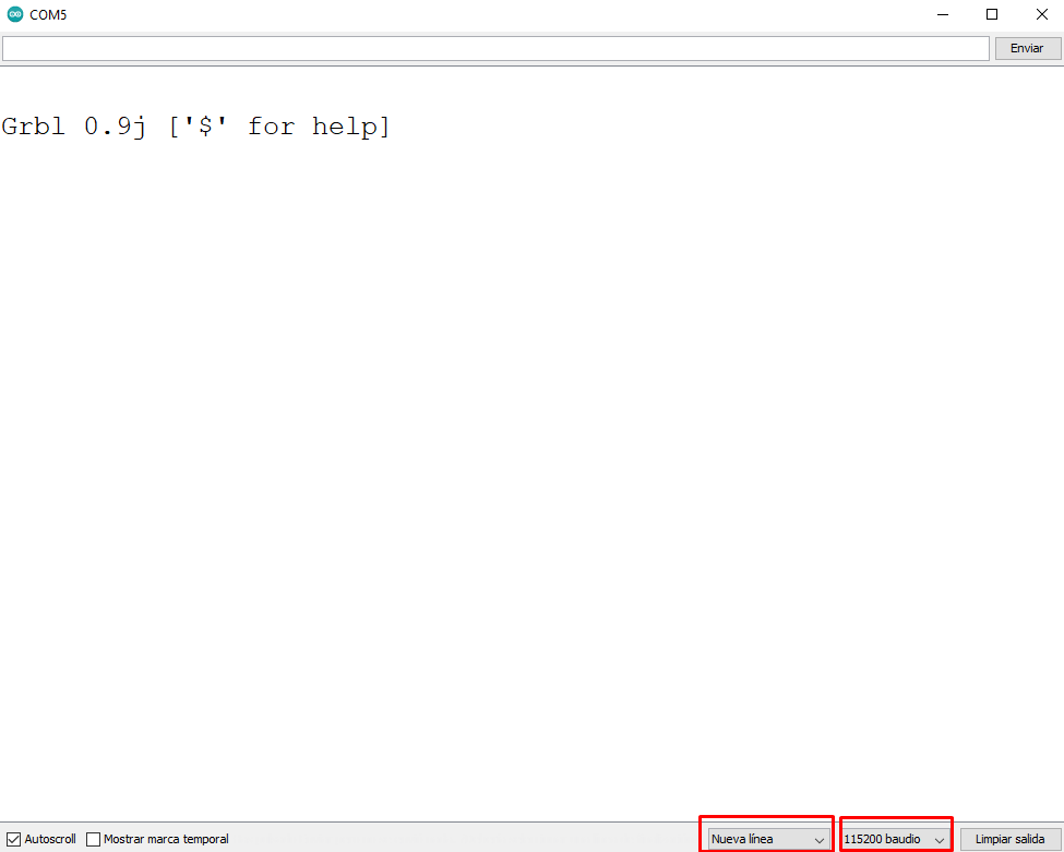
-Finally, you must check that the program is uploaded correctly through the serial monitor, you should get a message like this:
Chef's Notes:
-Remember to select 115200 baud and "New line" in the boxes below.
-You can use the serial monitor to directly modify the parameters of the CNC, send the command "$" and "$$" to see the options that you are allowed.
Calibration
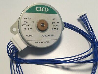
-Do not sing victory yet, we have to calibrate the GRBL parameters for our Model. For this, the most important thing is to verify the steps of our stepper motors of our X, Y and Z axes.
-Our CNC Models have the CKD-J262-859 motors in all axes. We can see in the image that this motor has 3.75 ° per step and that means that I will need 96 steps for one turn or 1mm.
-The 96 steps represent one turn or 1 mm of advance, this number must be divided by the number of threads of our advance studs (in our case between 2), which results in 48 steps per millimeter (mm / step).
Chef's Notes:
-The calculations are essential but they are not always final, I recommend that you test these parameters and edit them until you reach the correct one, but taking as a reference the value generated by the engine data.
CNCjs-Flatcam
-Now it is turn to cut our Gerber that we generate in easyeda, but for this we require the teamwork of the CNCjs and Flatcam softwares, follow the following steps:
Flatcam:
-This software will allow us to obtain the routes of our gerber format that we obtained from easyeda, for this we must go to the flatcam download page.
-We must import our gerber from easyeda and generate the Gcode and then send it to the CNCjs, you can guide yourself through the following video:
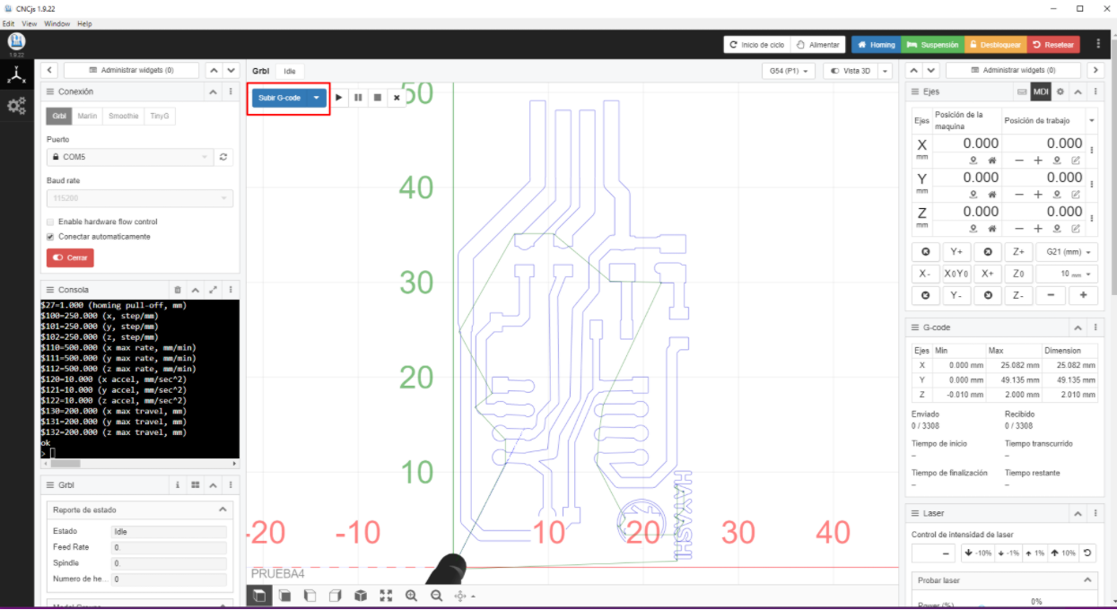
-Now it is CNCjs turn, for this we must download the program from here,then we must import the Gcode file generated by Flatcam and that's it.
Chef's Notes:
-Don't forget that we must first calibrate the home of all the coordinates through our CNCjs and the right column called the work position (you must place the axes in the desired position and then click on the location sign next to the plus).
-CNCjs has a web version, explore it and you will be surprised.
-This is how the final result looks like, it should be noted that this week we also gave the CNC a ride, at this rate the machines will have traveled all of Lima in a few weeks.
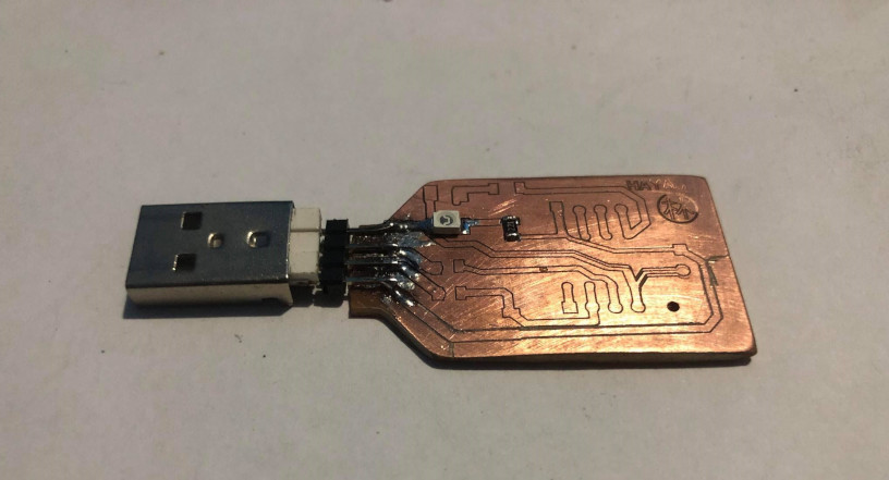
Time to weld
-Now it is turn to weld the components, for this I will give you the following recommendations:
-You must pass a sandpaper of water through the pcb before releasing it so that there is no trace of copper on it (it should be that clean).
-Check with a multimeter that there is no short between the tracks.
-If you do not have the Stencil tool for your plate, paste tin or heat gun (I mean nothing), do not worry that you can still do it (as I do), I recommend that you first tin the contact pads a little in the pcb.
-Be patient, start with the test led first (I recommend placing a test led in series with a resistance between VCC and GND in every circuit to verify that there are no shorts on the power pins).
-For each step you take, you must test continuity if this last weld went well or badly (it is advisable to test every so often, so you will know that the last step was the error).
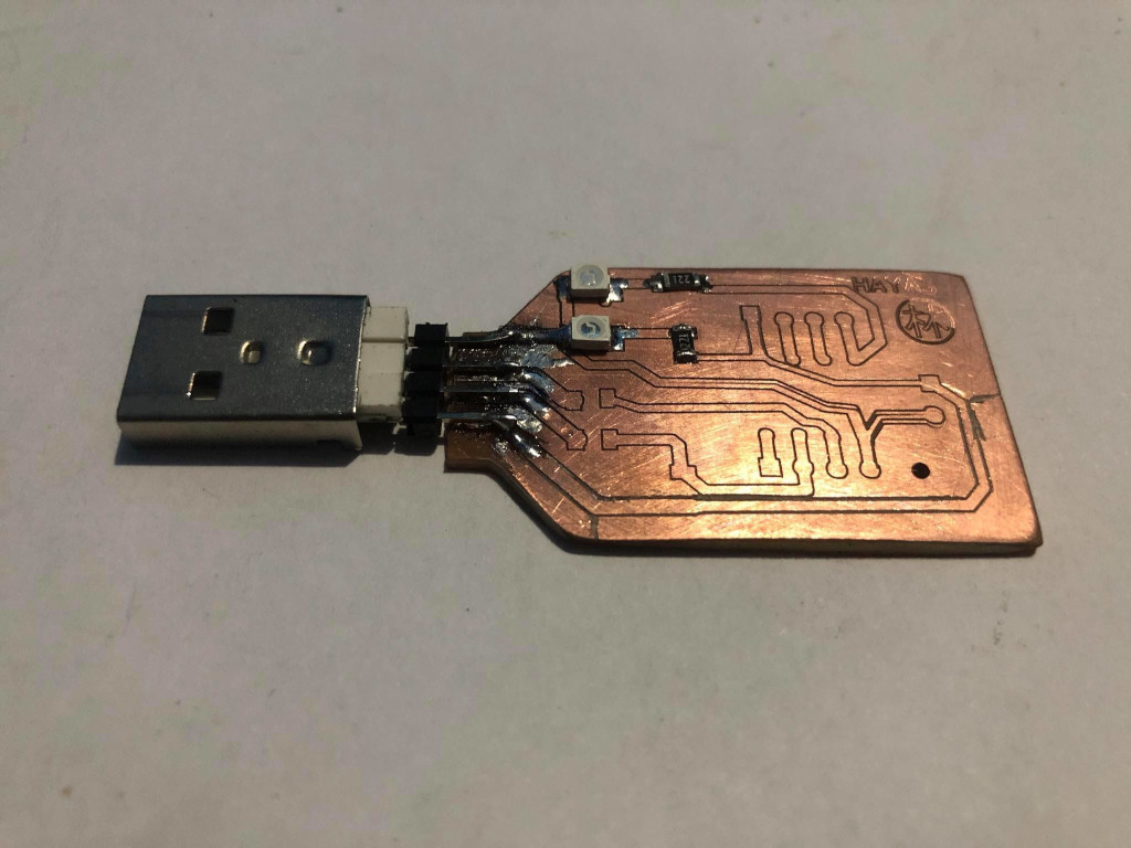
-Finally, contemplate the beauty come true.
Chef's Notes:
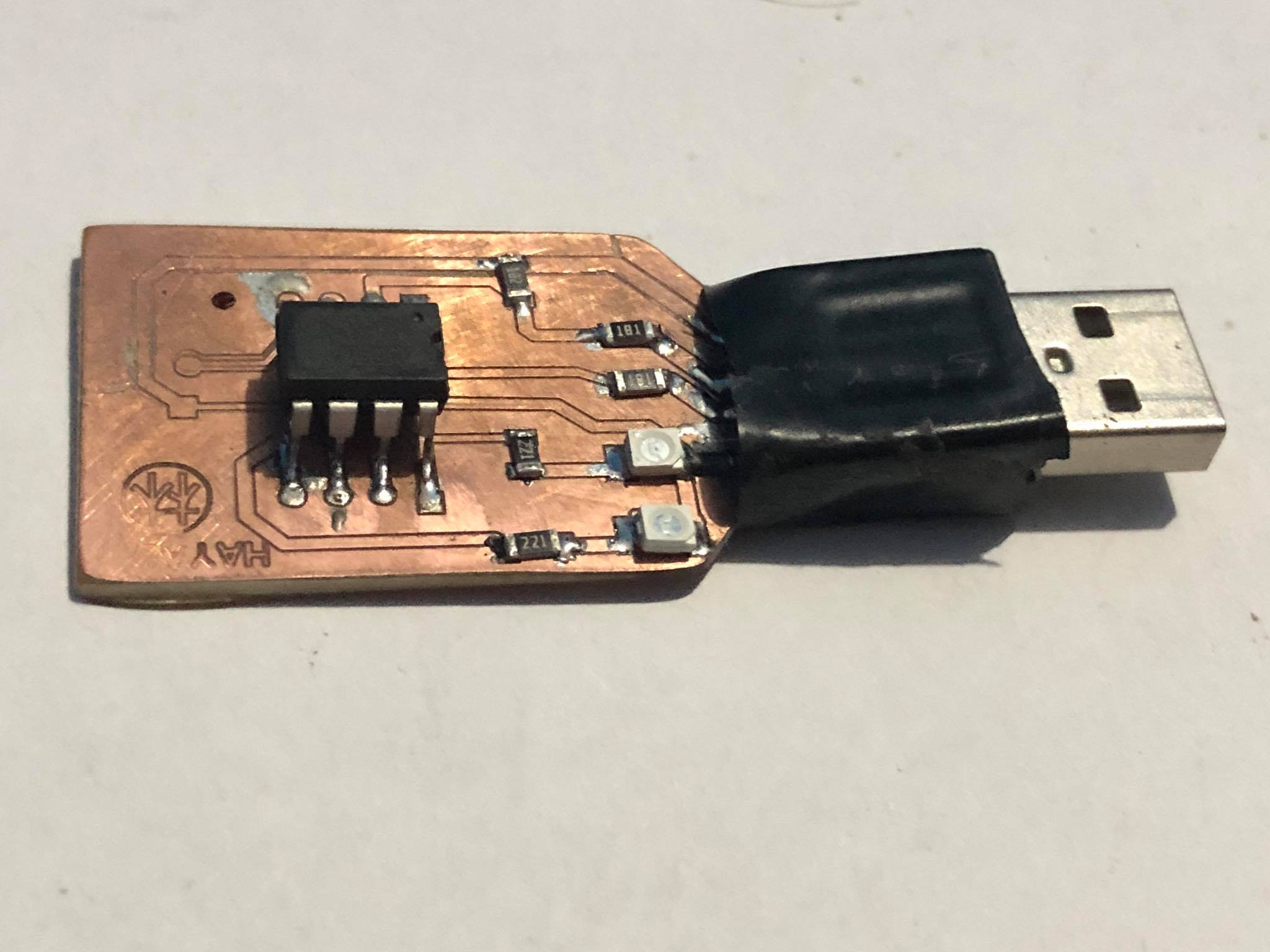
-The microcontroller is the last thing you should solder and it has to be after the bootloader is installed or you could design communication pins to connect with the arduino that will pass the bootloader information to it.
IT'S ALIVE
-At this point if you did not have an aneurysm or a mental collapse consider yourself lucky, but calm down I promise that these will be the last steps:
Attiny85 bootloader
--I know it looks beautiful but it still needs to bring it to life, remember that even the Attiny85 doesn't know it's an arduino, but don't worry, we'll give you the news.
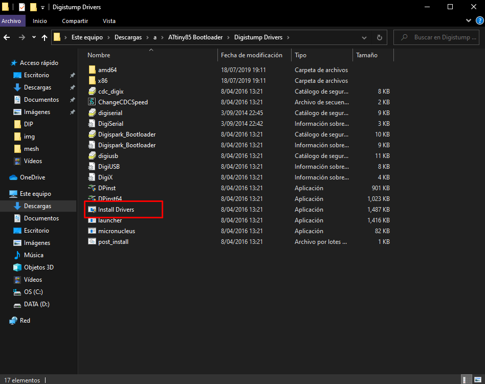
-First we must download the necessary drivers here,which we will install on our pc.
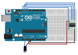
-Once ready you must use another arduino (arduino uno or nano) to be able to load the bootloader to the attiny 85, once our arduino is connected we must load the Arduinoisp example (file / examples / arduinoisp / arduinoisp).
-Now we need to build the following circuit to be able to pass the bootloader to our attiny85.
Chef's Notes:
-The 10uf capacitor is not essential, the other connections are necessary so that you can pass the bootloader to the attiny85.
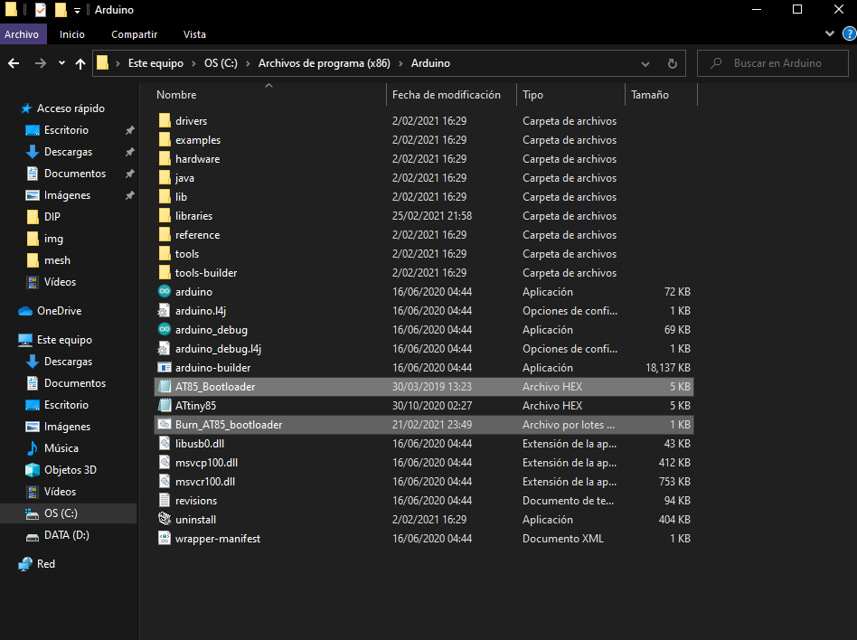
-Now it is the turn of the bootloader, we must download it from here.Finally we must edit the file "Burn_AT85_Bootloader" and change the command "-PCOM4" ”By the port where our arduino is connected (we can find it through device manager or arduino tools).
-Now we must copy those 2 files and copy them directly to the root of our arduino folder.
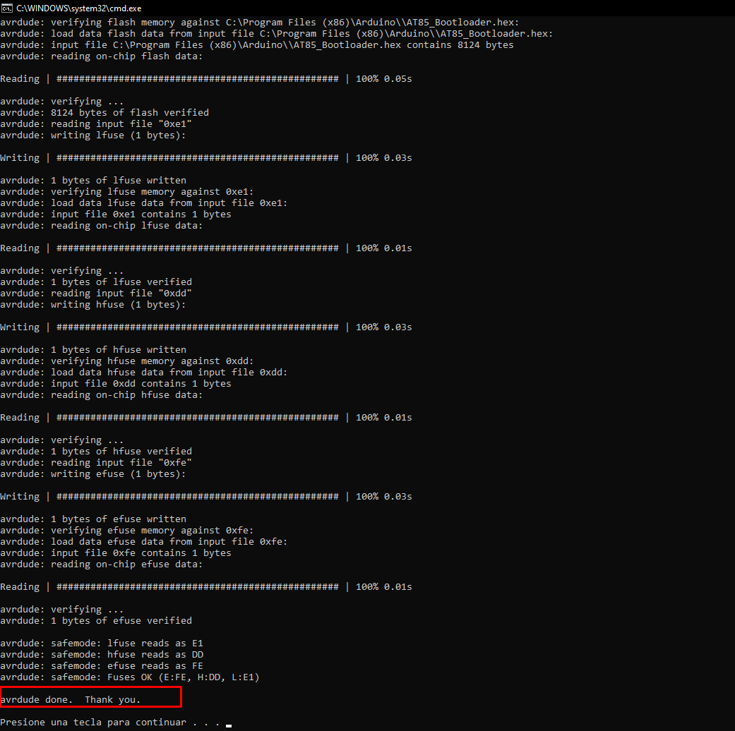
-Now we just have to execute the file "Burn_AT85_bootloader" and a final screen should be generated with the message "avrdude done" like this:
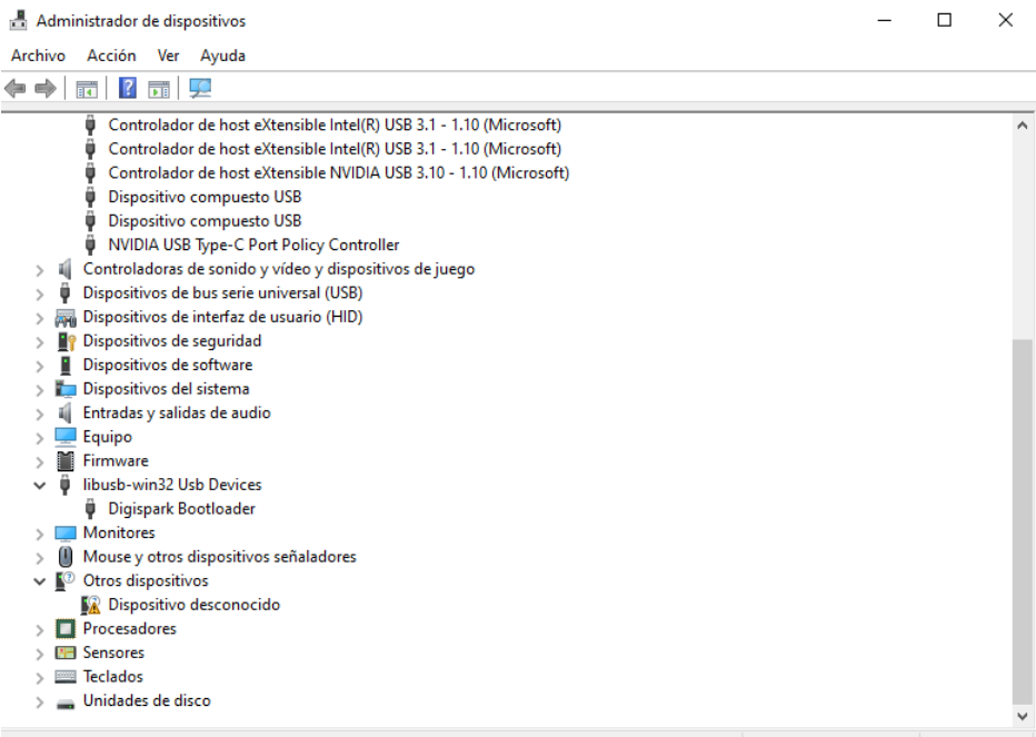
-The moment of truth has arrived (solder your booted attiny85 to your PCB), we connect our board and we will hear the sound of victory (the tucutum that recognized a USB) and you can check it through the device manager:
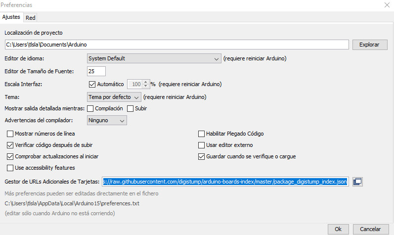
-Your board must recognize as a "Digispark" module, it's time to test our new mini arduino. Now we must install a new board manager in our arduino, for this we go to "file / preferences" and put the following (http://digistump.com/package_digistump_index.json ):
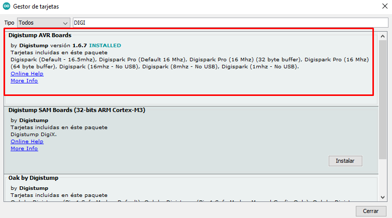
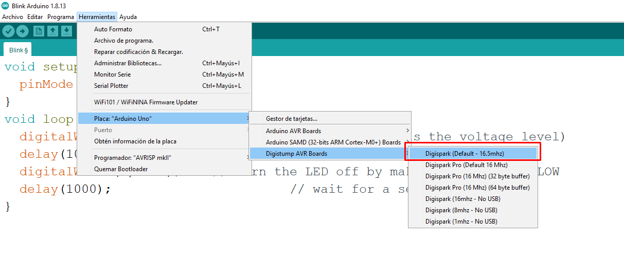
-Then we go to "tools / boards / card manager" and look for "Digistump AVR Boards"
-Now we just have to choose the correct plate:
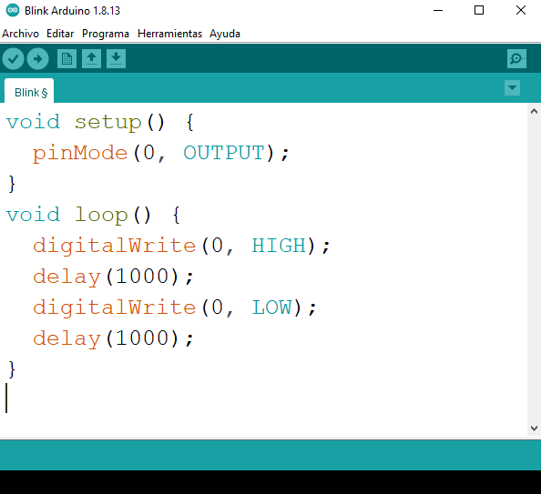
-Finally we uploaded a program and EUREKA, we have achieved it.
Chef's Notes:
-This mini arduino has a very curious way of programming, you must upload it without having it connected and then in the black console below it will notify you so that you can connect it.
GROUP ASSIGNMENT
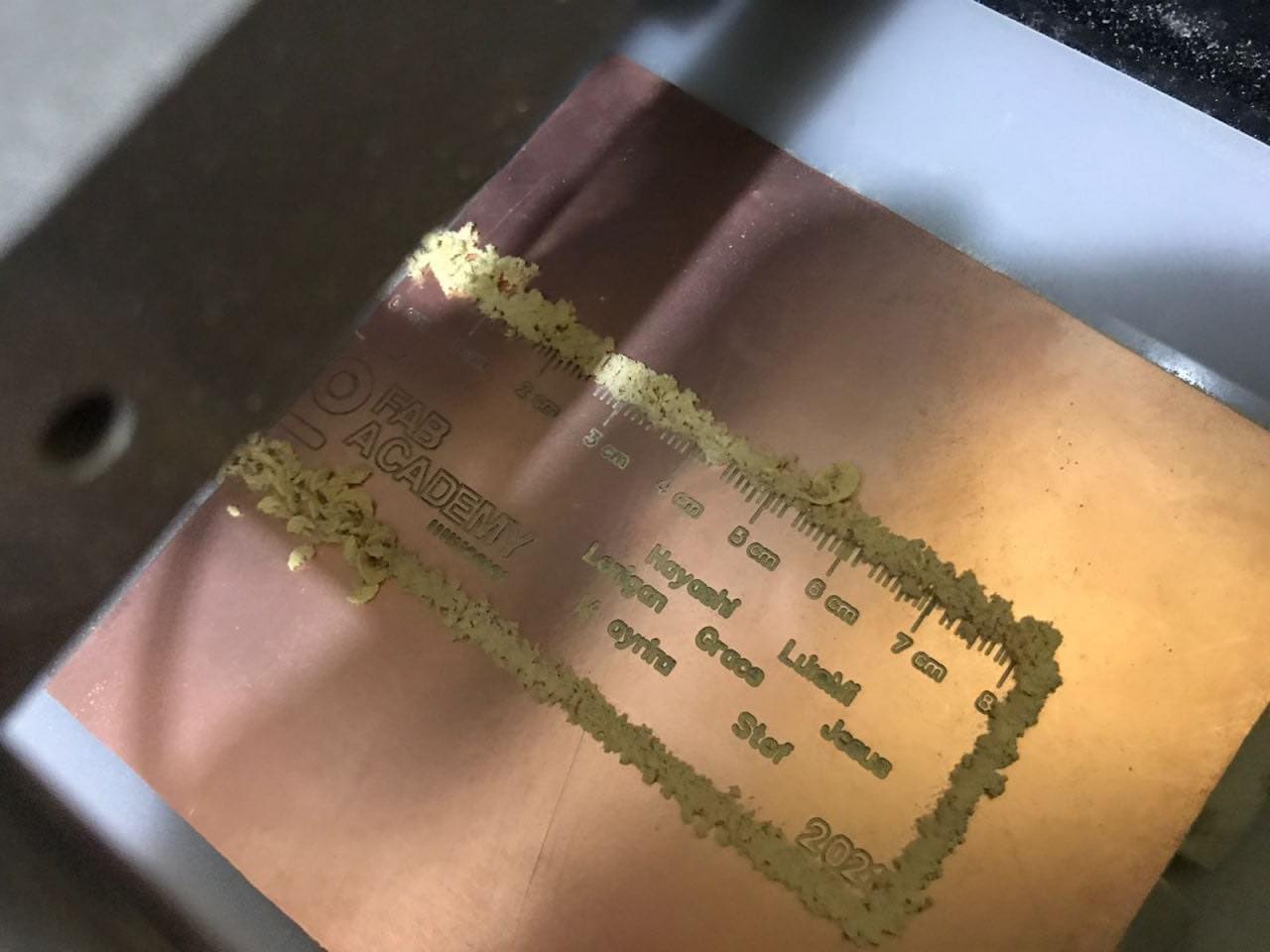
The group work this week was easier compared to the whole machine repair, we wanted to visualize the limits of the machine and also do something collaborative, for that reason we got together in a video call and created a design to later be milled. design was made in easyeda and can be viewed at the following link.
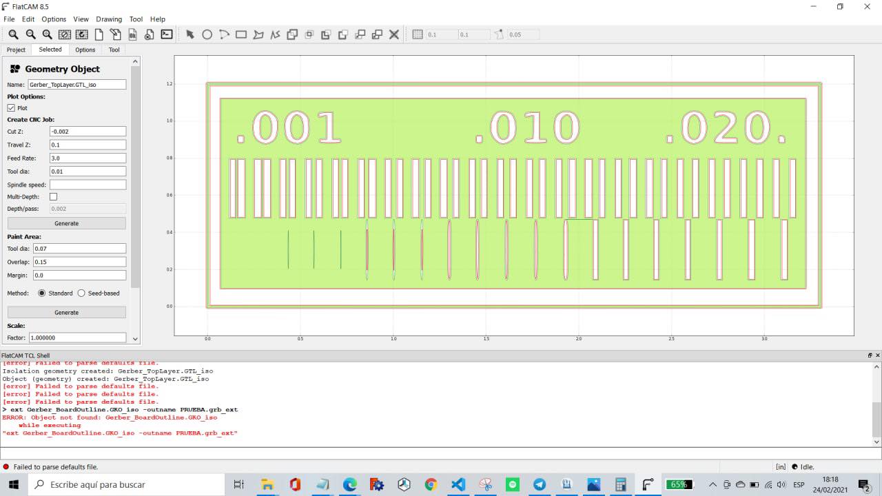
-A final test was carried out with another design and these were the results: