Development
Final project development list:Introduction Week2 - Computer-aided design week8 - Embedded programing Week10 - Input devices Week11 - Molding and Casting Week12 - Output device Week13 - Networking and communications Week16 - Applications and implications Week17 - invention, intellectual property, and income Week18 - Project development
Touching the untouchable
“Hoy toca neurociencia” (cerebral hemispheres)
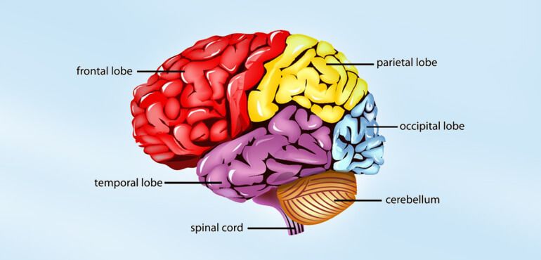
“Hoy toca neurociencia”(cerebral hemispheres) is an interactive exhibition project for the visually inpaired and blind persons. Although it is developed with the disability in mind, it is inclusive and accessible to everyone. This project educates on the functions and focuses on providing information of the interior of the human body. My project will finalize the development made so far and focuses on one element of this exposition. The idea is to develop a representation of the brain that will provide a vibration at the different hemispheres being described by an audio track. The user will then be able to distinguish the location of these parts.
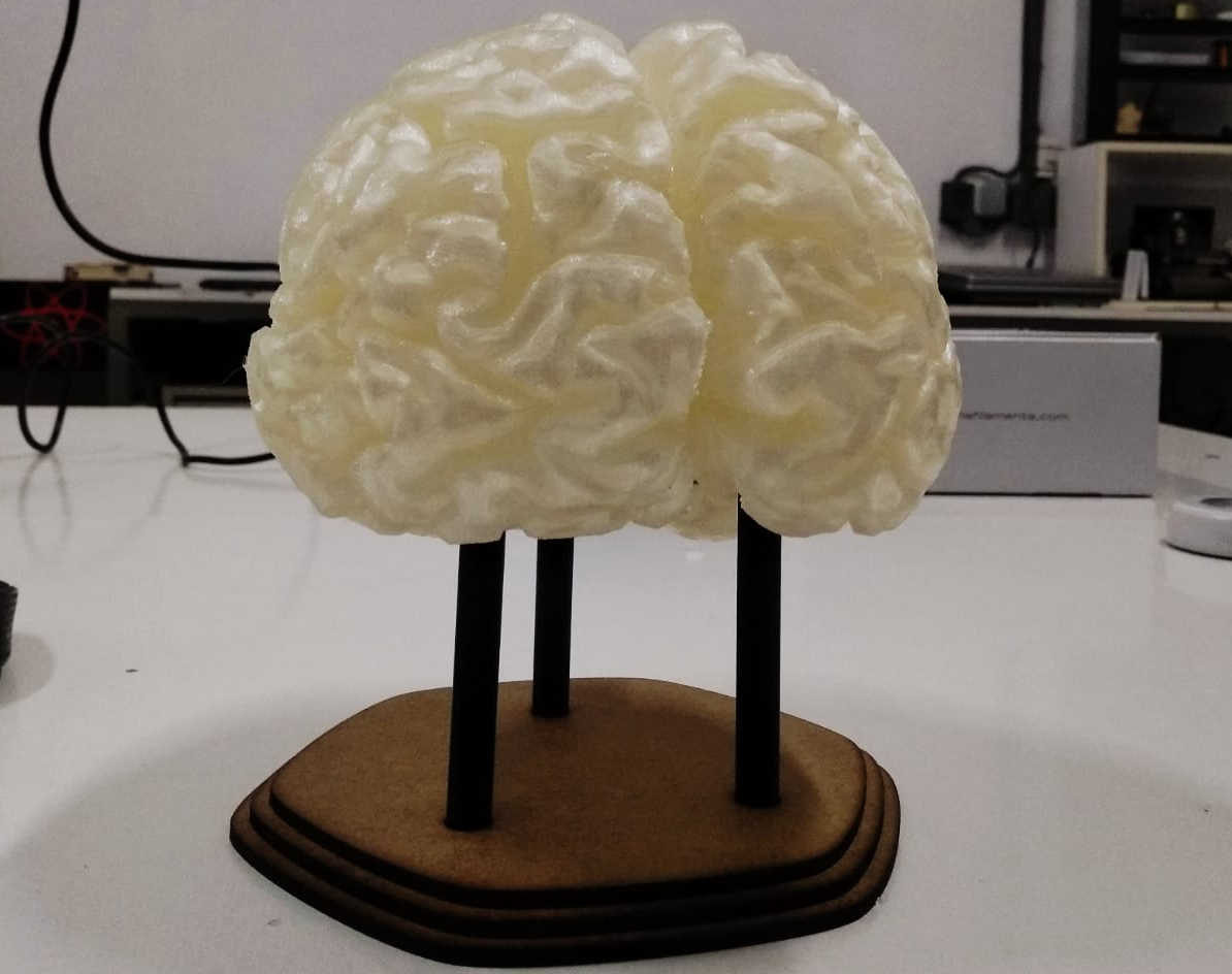
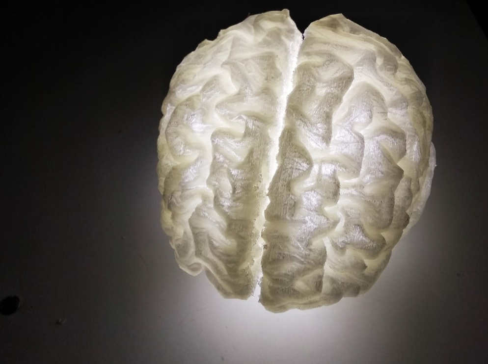
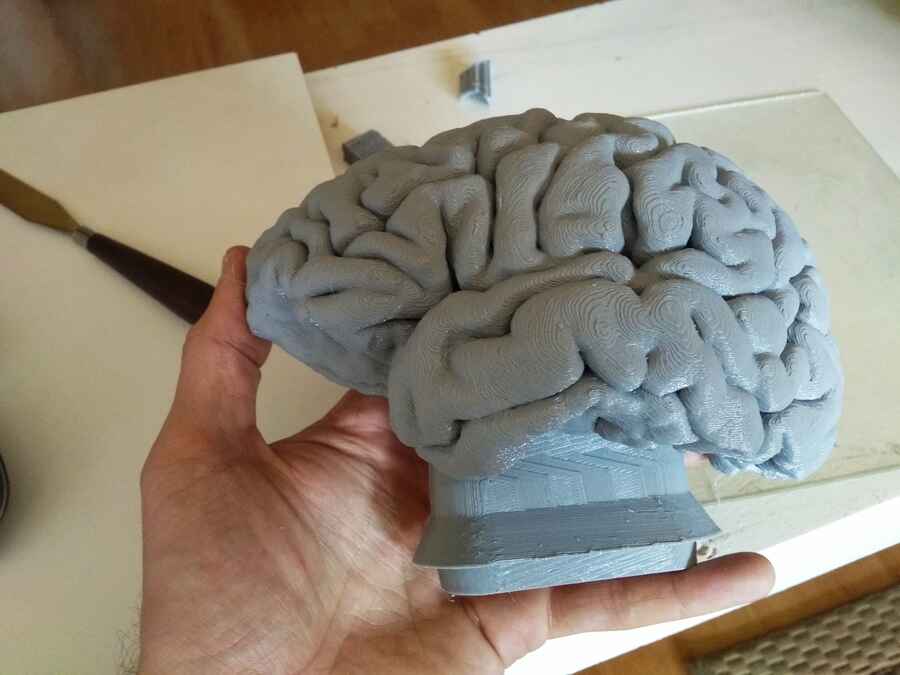
Here is the collection of models by NIH 3d exchange where the brain was downloaded.And some images of the last prototype.
I found Harry´s documentation, who did something very similar here that could helpfull.
NOTE: I would like to modify the model for a better mold. As I see in the documentation above that the gaps are quite deep and it may have caused problems, something like this could be better.
We also had a meeting with the team, Delia (fablab director) and Jenny (neuroscientist). We needed to concretize a few details about the content and other matters for the development of the exhibition project.
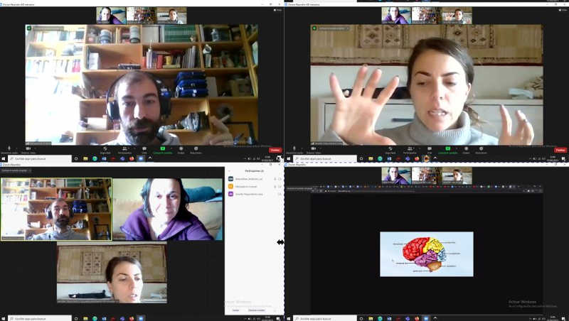
We talked about the efficiency of the content, how the material should feel: rigid but still squishy. And the different regions should be distinguished.
How big should it be? As real as it can.How about the content? Fine, for now to review when sistem is working.Is silicone the right material? Yes for now, we are looking for something soft but that keeps its natural shape and still squishy.Can I replicate one side exactly as the other? Yes and not, “the temporal lobe” is separated from one side to the other, I guess this is something we can add in the voice track and I don't think it would be a problem for the construction.
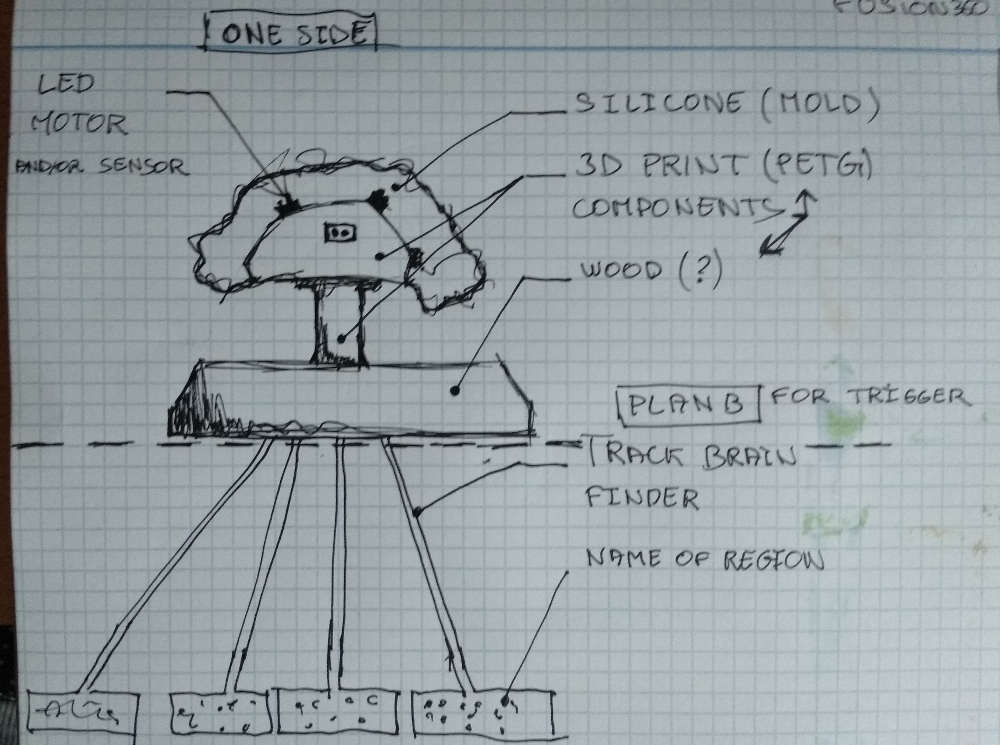
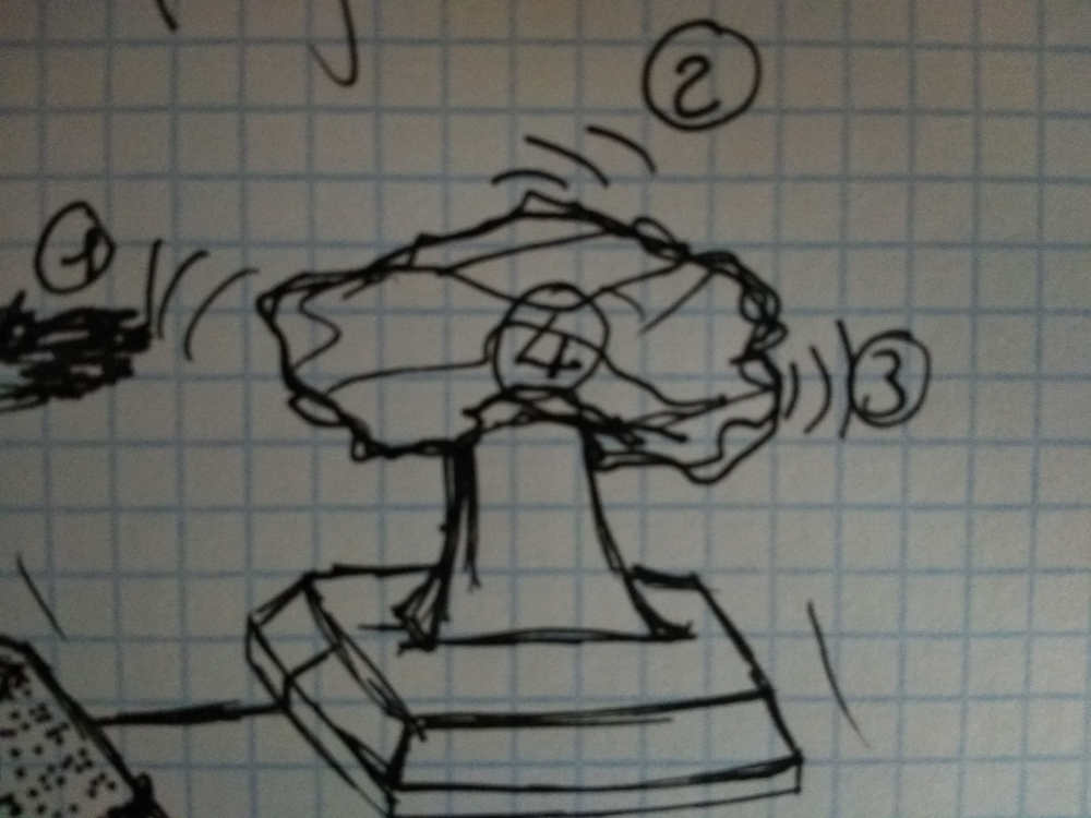
A quick sketch to see how different the part could be.
I would like to first start by giving very little control to the user (1 button). I think a cycle/routine could be better. For example:The user can read the instructions and activate the routine.Each motors+LED will follow that routine along with the audio, while the user listens to the information, he can touch the brain model and feel where the different vibrations and how the location of theses vibrations changes to point out the different regions of the brain.
Note: As an option for later on the user could maybe have control over the routine like, pause, play, back to the start, stop?
Week2 - Computer-aided design
Final project development list:Introduction Week2 - Computer-aided design week8 - Embedded programing Week10 - Input devices Week11 - Molding and Casting Week12 - Output device Week13 - Networking and communications Week16 - Applications and implications Week17 - invention, intellectual property, and income Week18 - Project development
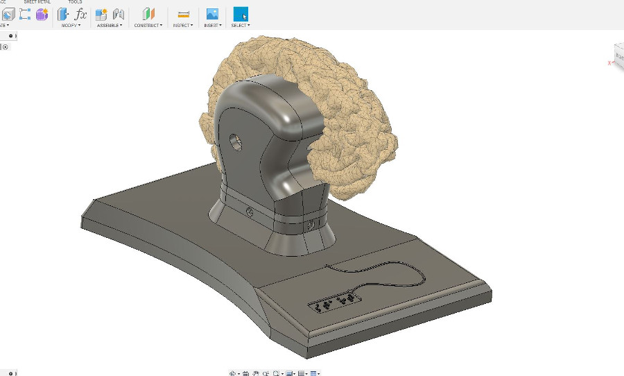
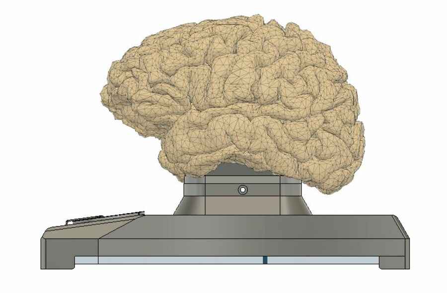
I started designing a representation to try the renders and other functions in the software that I didn't know like, importing components libraries and better manipulate the user parameters. I am not too happy with it but it is just a representation...
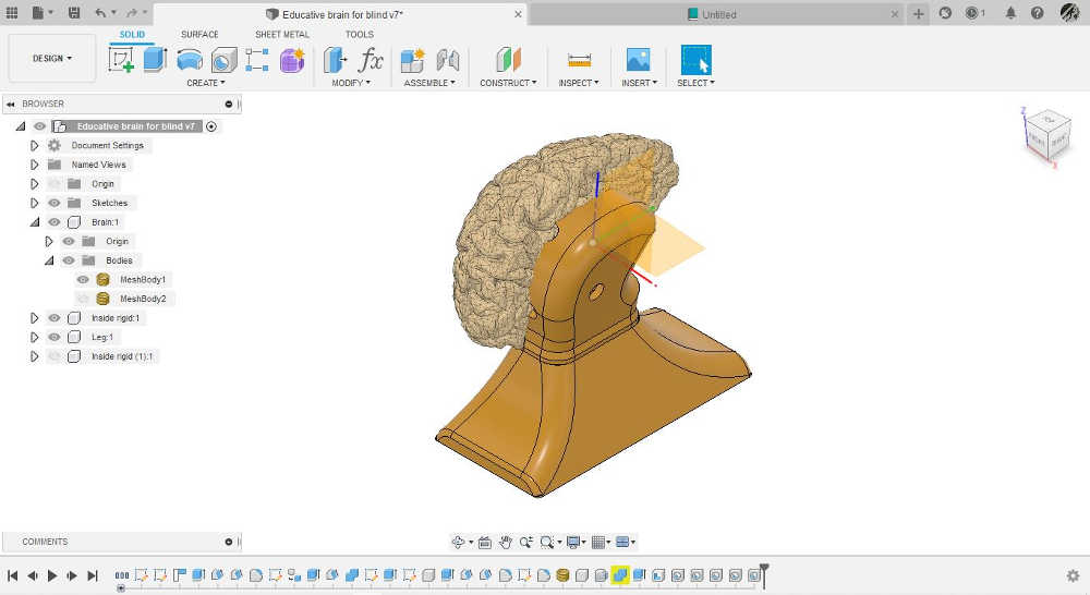
As a first draft it is not bad but I can alreadi think of a few things I would like to change like the the base, I think it needs to be lower, more stable, I also want to unclude the controls (it maybe a little early)...I will try to do everything in fusion, although I would like to try other tools, I like the idea of beeing able to produce everything (electronics, 3d and 2d design, etc...) in the same software.
Week8 - Embedded programing
Final project development list:Introduction Week2 - Computer-aided design week8 - Embedded programing Week10 - Input devices Week11 - Molding and Casting Week12 - Output device Week13 - Networking and communications Week16 - Applications and implications Week17 - invention, intellectual property, and income Week18 - Project development
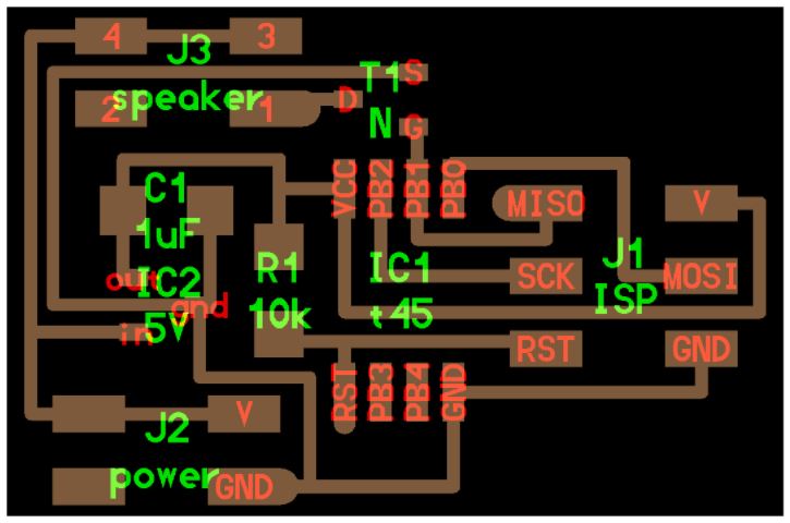
Following on to the development of the electronics for this project, and after the work done in week 8, I am now looking at the next version that should solve the problems encountered.
The main board needs to include a solution for the use of an external power sourse. Or altyernatively, a resistor/transistor/diode/capacitor configuration to amplify the current and protect the attiny1614 from possible motor´s voltage spikes. Here is a usefull page, to be confirmed.
Week10 - Input devices
Final project development list:Introduction Week2 - Computer-aided design week8 - Embedded programing Week10 - Input devices Week11 - Molding and Casting Week12 - Output device Week13 - Networking and communications Week16 - Applications and implications Week17 - invention, intellectual property, and income Week18 - Project development
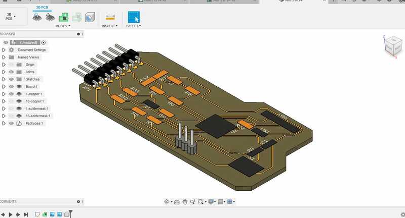
For the input, I will try to use a step response similar to the board done in week 10. I would like to modify it and design the electrodes dirrectly on the board (trying to have them as close as possible to the board) to combine them or some kind of connectable electrode to the existing board.
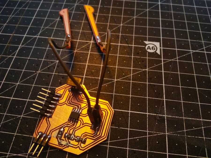
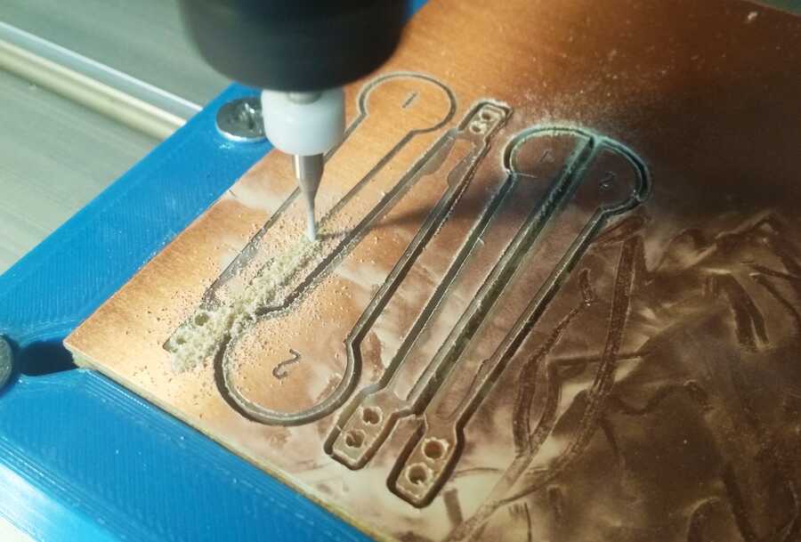
Here are the electrode so far I designed x2 pairs, let´s which one works better. (I preffer the semi circled ones).
week11 - Molding and Casting
Final project development list:Introduction Week2 - Computer-aided design week8 - Embedded programing Week10 - Input devices Week11 - Molding and Casting Week12 - Output device Week13 - Networking and communications Week16 - Applications and implications Week17 - invention, intellectual property, and income Week18 - Project development
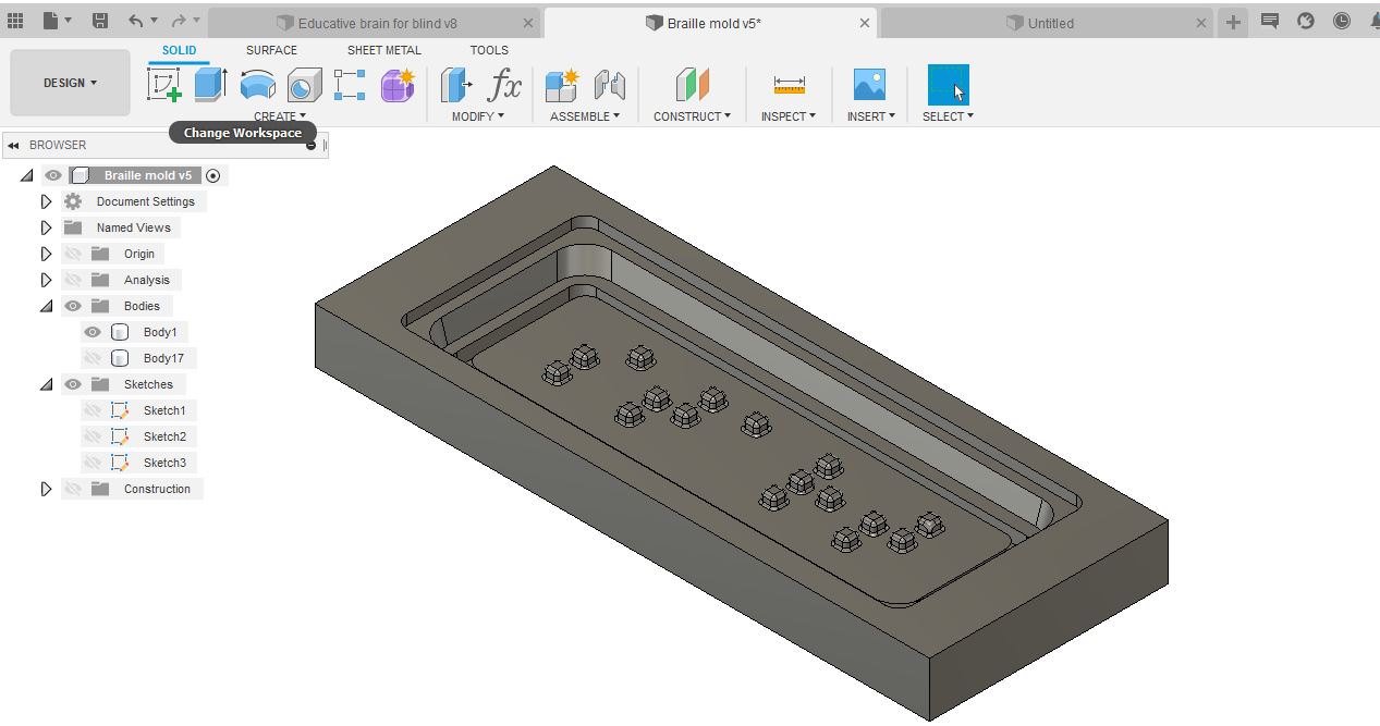
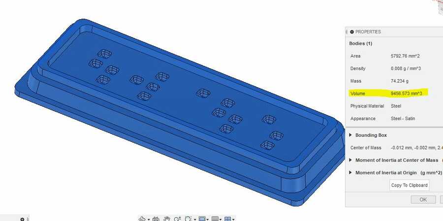
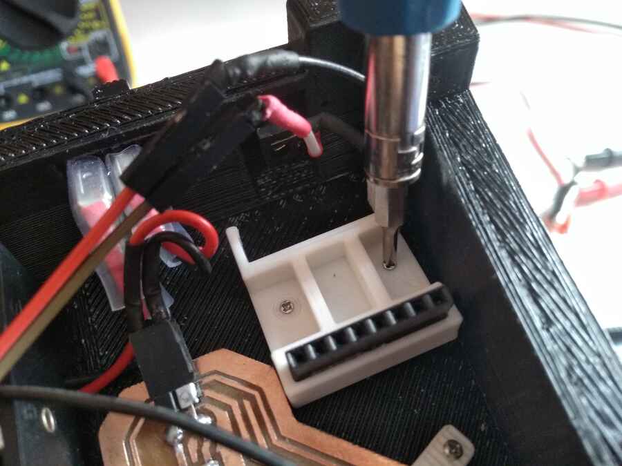
I am thinking to use different materials in order to procuce the brain, I am hoping to make a mold from a 3d printer model (resin) using alginate (first layer) reinforced with plaster. Also, in week 11, I have done tests that will help getting familliar with the materials and got good results producing the touching pad (user controls to start the routine) written in braille made of resin.

Some changes in the 3d model, I change the base (did not like that last one), so far I think I will 3d print it (unless I find a nicer way to do it), I may also add some weight to make it more stable (first I need to see how much space will the electronic take). I also incorporated the resin cast from week11 that will be the input and a track line (guide) to help the user find the brain.
I am also reviewing the original brain model, I need to edit it (smaller peices) to see how I will print it in the photon (SLA/resin). I am going to use FDM 3d printer, as I would like to keep the original size of the brain model and it will make it easier (I dont thing it will affect the result that much...I will do some tests further on.
Week12 - Output device
Final project development list:Introduction Week2 - Computer-aided design week8 - Embedded programing Week10 - Input devices Week11 - Molding and Casting Week12 - Output device Week13 - Networking and communications Week16 - Applications and implications Week17 - invention, intellectual property, and income Week18 - Project development
While redesigning the board for this week´s assignment (output devices), in witch I hopped to solve the issues encountered in week 8 with the motors, I have found an other issue. As I understand, the pins used to control the motor must allow for PWM control in order to use the configuration with the allegro and since I need x2 pins per motor and ideally would need x5 motors, in that case, neither the attiny 1614 or 3216 would have enough pins. I am also using the Tx pin, which happens to also be a PWM pin for the networking week...let´s see if we can find a way to solve that...

I am also looking at intagrading the audio playback, Here is Neil´s example.
After talking with Adrian, it looks like it could be much more difficult than I thought...Here is a few interesting documentations from previous students that could be usefull :EduDavidRogerJavierAll have some how used audio as an outpout or sound in their projects, there is still much more documentations to investigate and it is ofcourse open to suggestions...
The audio output as a desciptive content for the user is a must, my primary target user is blind so the ways to convey the information is very narrowed down...In anycase, After talking with a friend and following his suggestions, I am taking a look at the DFR0299 mini MP3 player for arduino that could be simpler to integrate on my board and a solution...

Week13 - Networking and communications
Final project development list:Introduction Week2 - Computer-aided design week8 - Embedded programing Week10 - Input devices Week11 - Molding and Casting Week12 - Output device Week13 - Networking and communications Week16 - Applications and implications Week17 - invention, intellectual property, and income Week18 - Project development
In week13, I tested the network that I would like to have for this project, I need to build an other x2 nodes, 1 with another x2 motors (I may keep that for the next spiral) and a another for the audio output.
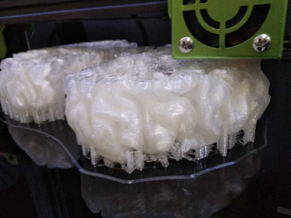
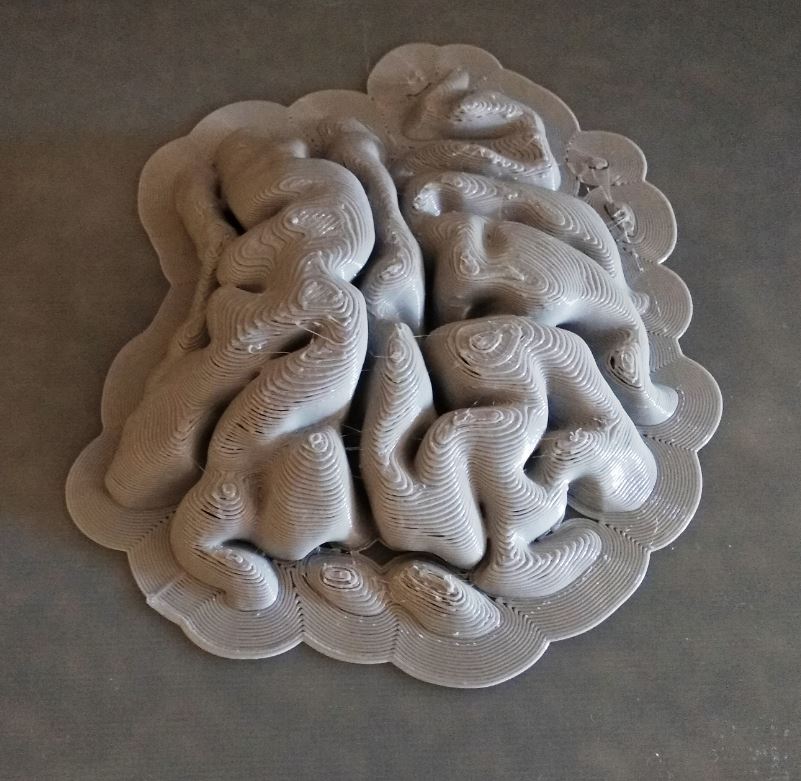
I also check out the original brain model, as it is too big for the resin printer we have and I´ll be using an FDM 3d printer, I am hopping to smooth it down. I printed a small part of the brain in order to do some test regarding the gap filling method. ...
- Spackle or putty filler - Wood filler - Superglue and baby powder (or baking soda, NOTE: could react with come of certain glue components) lots of cleanup requiered, for small parts only. - Universal glue and baby powder.
I will have a look at what I have and do some tests...
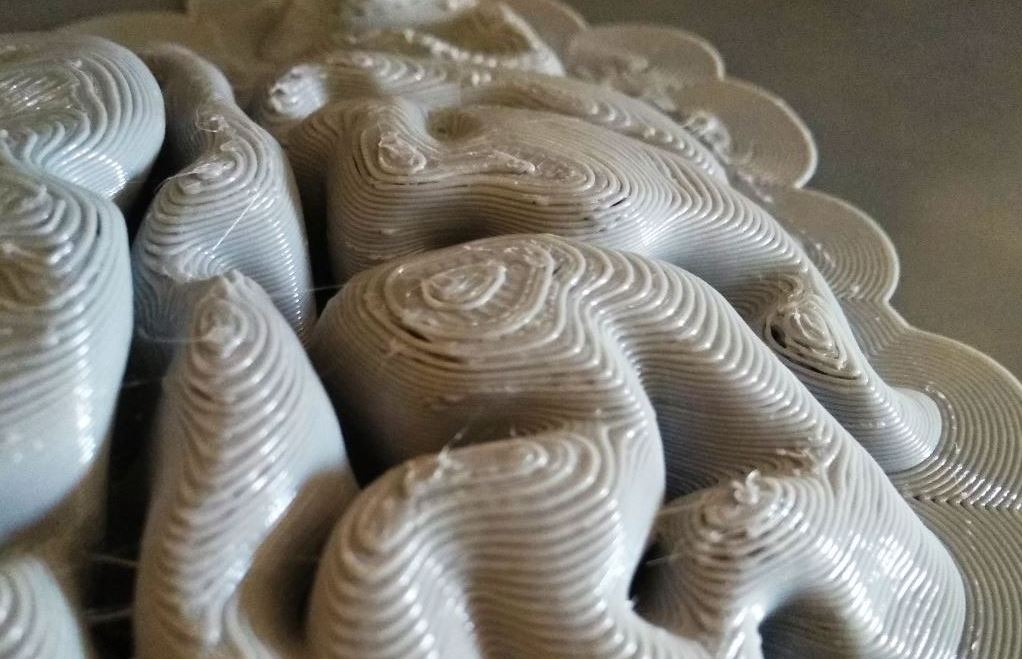
The universal glue and baby powder I used...

The result without any baby powder, just glue, it looks fine at first when applying but it runs off before it has time to set....
...with baby powder, on the other hand, it looks hugly but seems to stick to it better and also feels better to the touch when dry (smells nice to :-). I also exagerated on the layer height (0.28mm to gain time) of the print so I know I can get better definition and I may not need multiple coats, Ill do an other test to make sure it stick to the model as well...


Dry, no cleaning or sanding yet...It is probably worth but I am not sure it is really necessary for this proof of concept.

Week16 - Applications and implications
Final project development list:Introduction Week2 - Computer-aided design week8 - Embedded programing Week10 - Input devices Week11 - Molding and Casting Week12 - Output device Week13 - Networking and communications Week16 - Applications and implications Week17 - invention, intellectual property, and income Week18 - Project development
Here is a list of what I still need to do in order to finalise the project:- Re-design the electrodes- Design an other node (part of the network) with x2 more motors- Design the last node for the audio output and integrate the mini MP3 player to it- 3D print all parts needed- Cast all part needed (mold and brain, integrating the motors)- Test all electronics funcionality- Mount all and test- Add the bill of materials- Finish all requiered materials for the final project presentation (video and documentation)
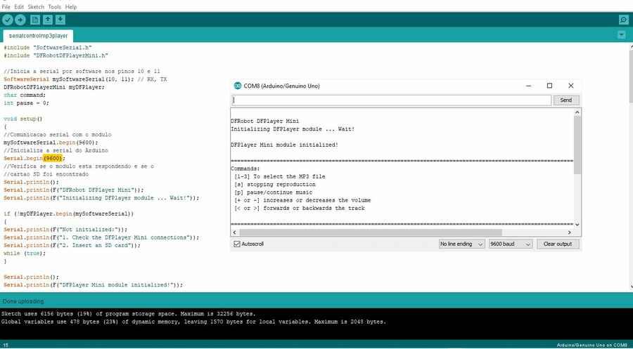
This week (16), I am also trying to figure out how to use the mini MP3 player as the audio output. I first red some information about it here, here, some more examples/mono and stereo wiring here and the datasheet.
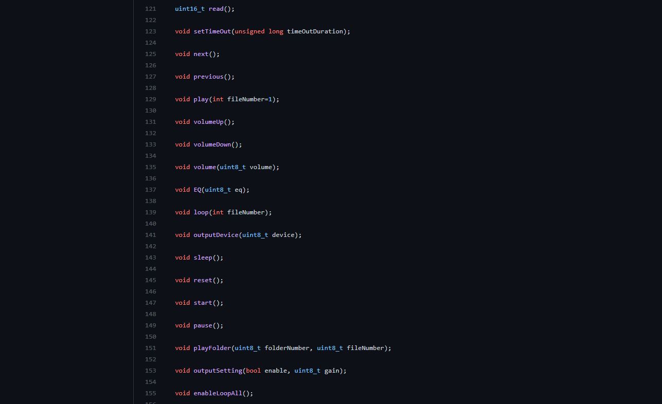
This is the .h file on Github where we can find the different commands that can be used to control the Mp3 player.
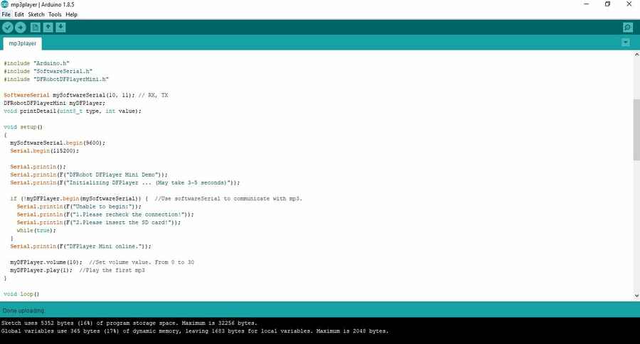
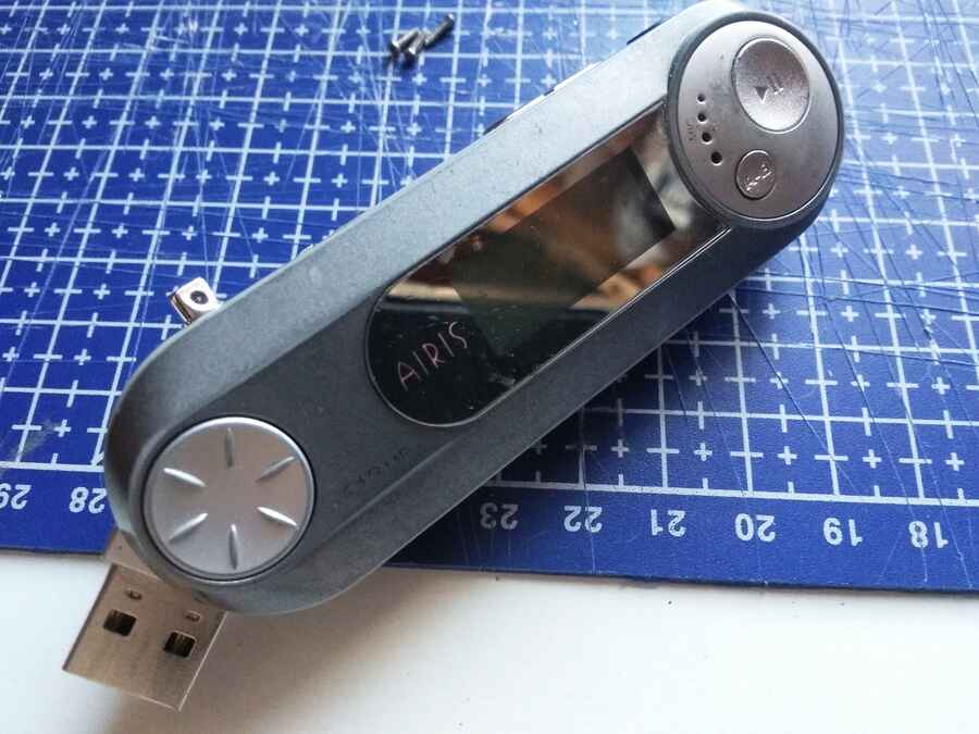
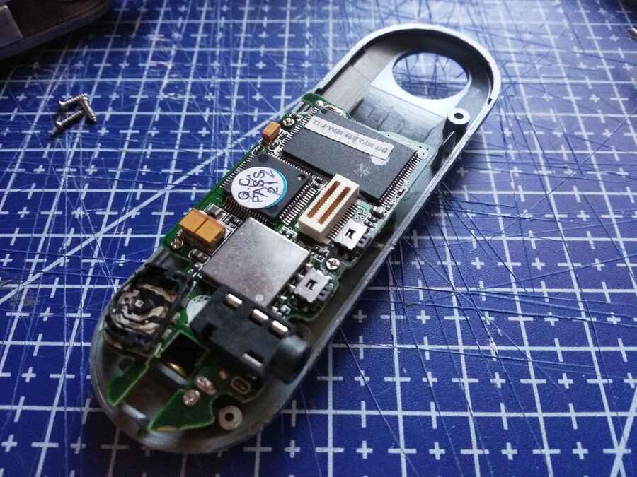
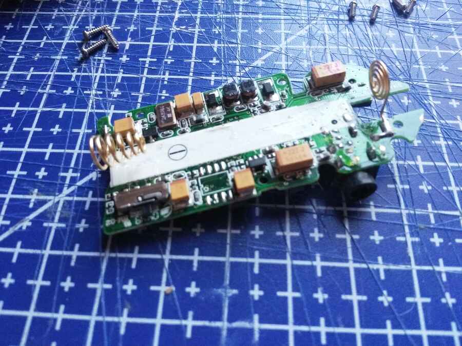
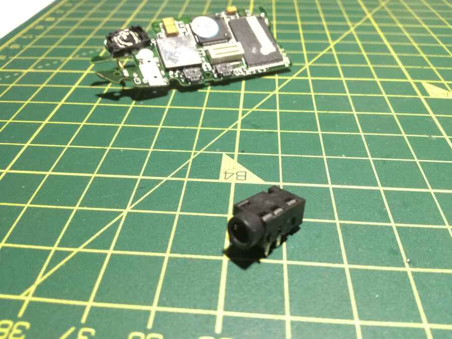
I will be using a bread board with an arduino and for the output, I am for now using my heaphone speaker so I am stealing the jack plug from an old MP3 player that has been around doing nothing for too long (I don´t even think it works anymore)
Here is the set up I used to test it, I also tested it with an external power supply for the mp3 player...So far, I have tried many different codes in order to figure out how to include the Mp3 player in the network. I was able to make it work with the full function code provided here, I put short Mp3 file (bird sounds) for now.
Just a reminder...

Now I need to work on the code...
Week17 - invention, intellectual property, and income
Final project development list:Introduction Week2 - Computer-aided design week8 - Embedded programing Week10 - Input devices Week11 - Molding and Casting Week12 - Output device Week13 - Networking and communications Week16 - Applications and implications Week17 - invention, intellectual property, and income Week18 - Project development
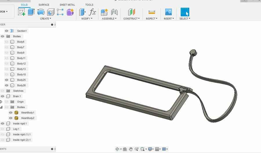
I also polished the 3d models, on one side I prepared a print that will be the tool to make the mold. On the other hand I also have the base ready and I think there should be enough space for the electronics.
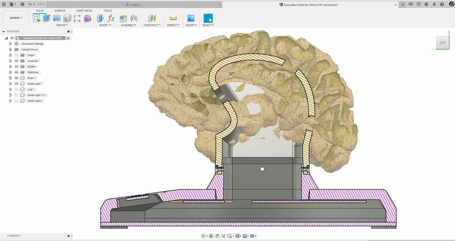
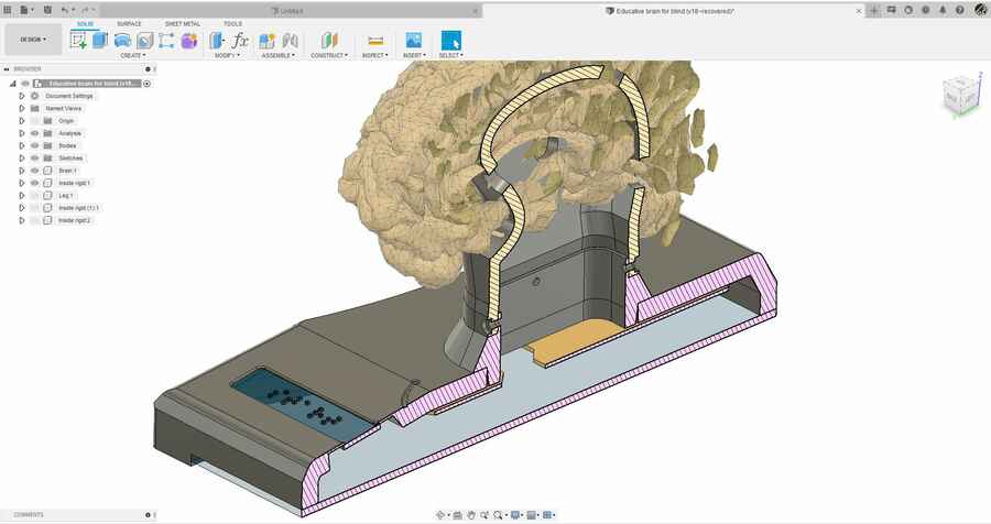
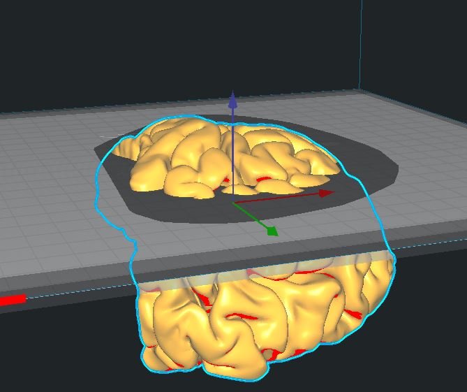
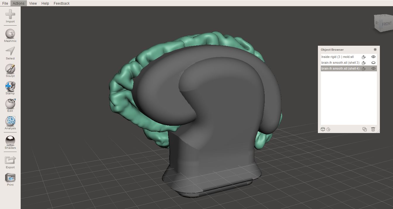
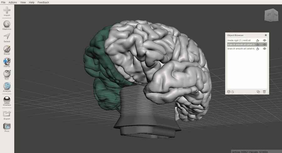
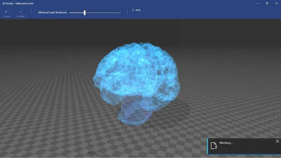
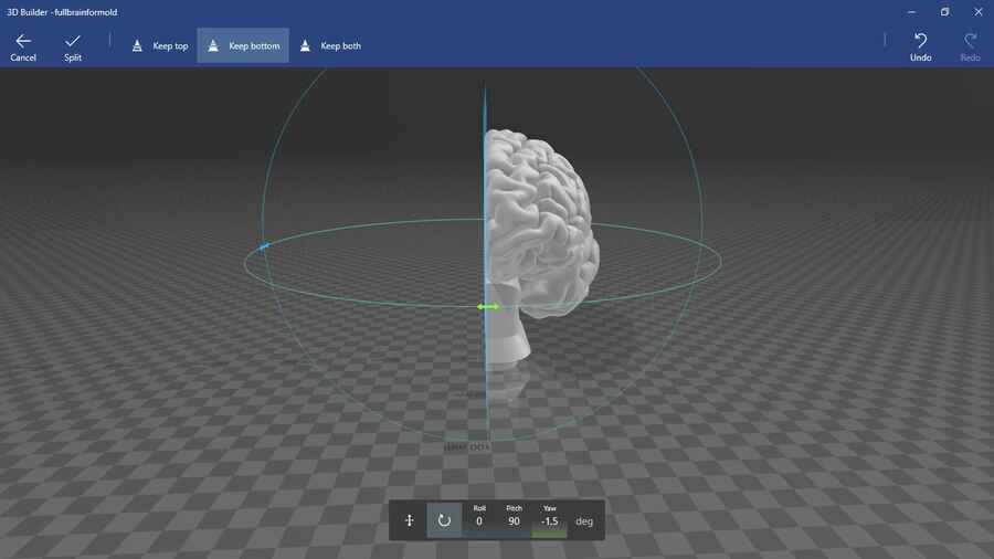
To print the model I used a smoothed down version (not the one used in fusion) that I edited in meshmixer. First to expand a little the model and to join the "neck" (center part) with the brain and make a solid model. I then, used 3D builder to slce the model in two in order to make it easier to print.
NOTE: The files used to make the mold turned out to be huge (together left and right hemispheres, with the neck, 43MB). The fusion file contains a converted low poly version that allowed me to design the rest of the pieces around it.!USE WITH CAUTION! The brain model downloaded from the NIH 3d exchange page, if your computer is a old or not the most beefed up, the file size really makes it hard to manupulate, I started on an I3 machine and it was really just about able to open it, on an I7 on the other hand was much better. Here is the file from an external repo as the size is way over the 10mb limit allowed here.

In 3D builder spliting an hollowing...
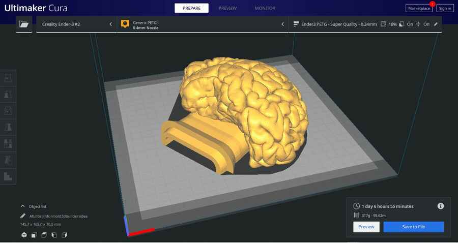
In cura to prepare the job...
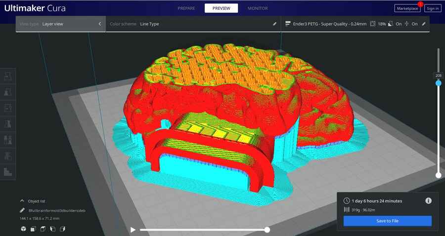
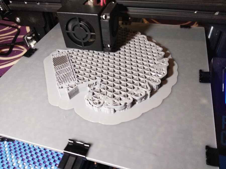
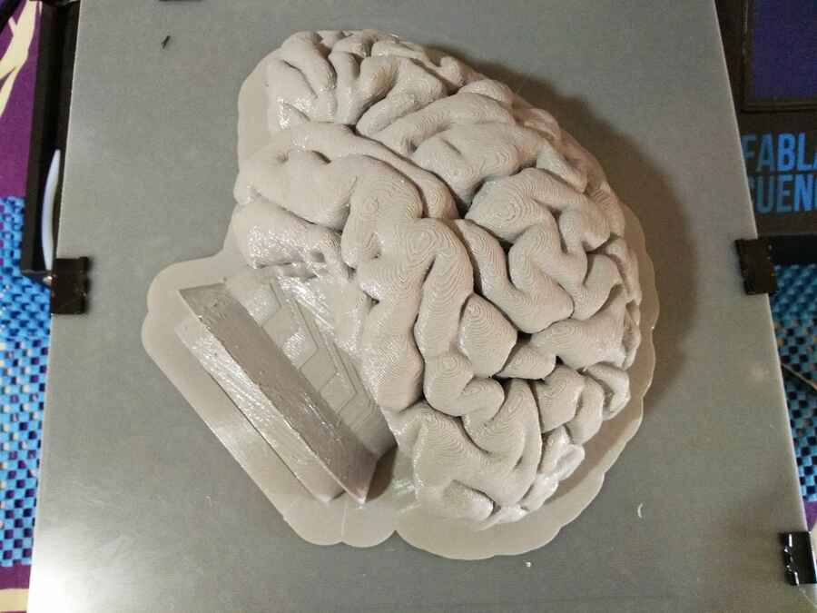
Here it is starting...and finishing...
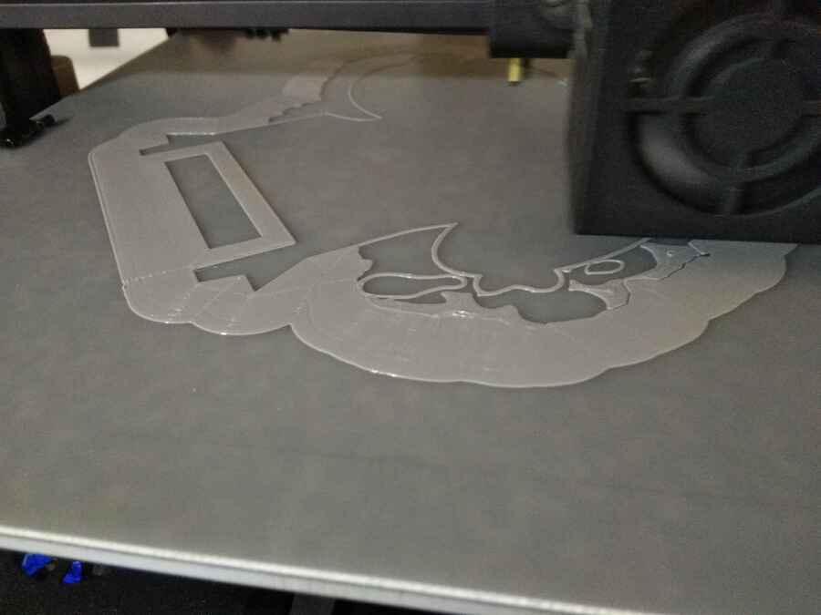
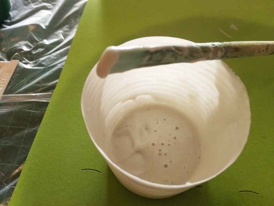
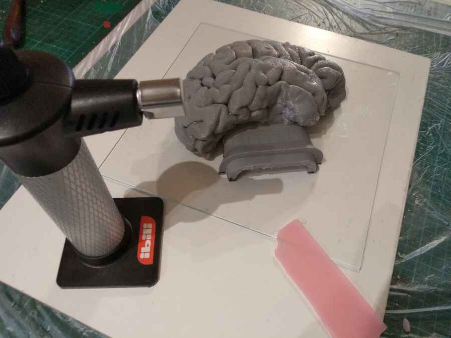
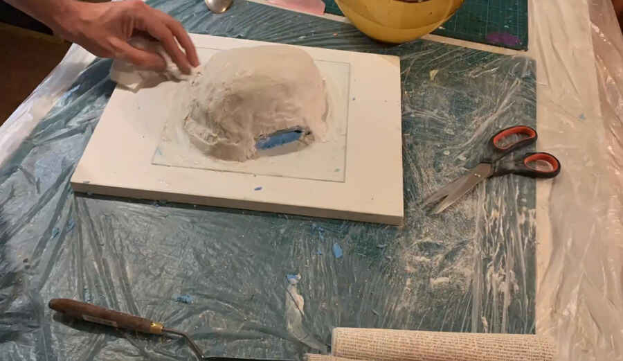
Preparing for the mold to be done with the algacast (see Week11) and plaster cloth bandage from Feroca. I first fixing the 3d printed brain model to a flat peice of glass with wax...
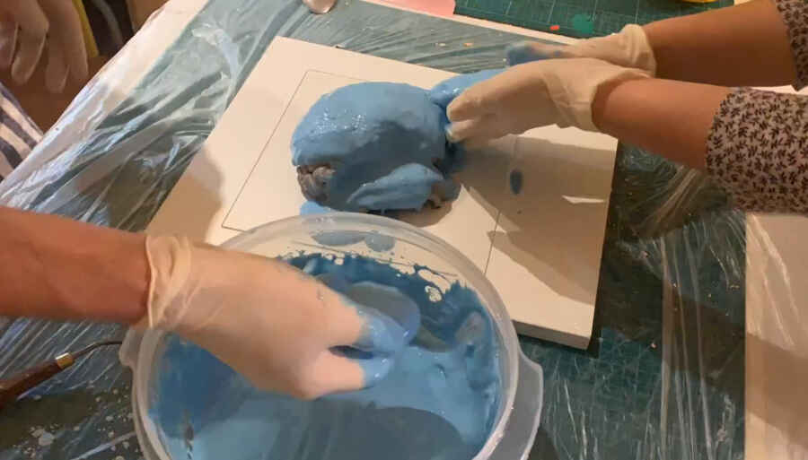
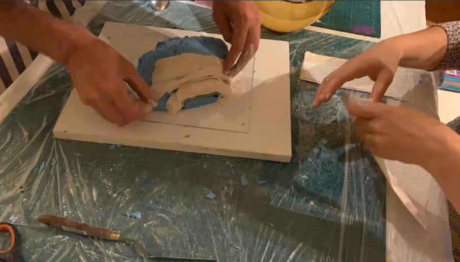
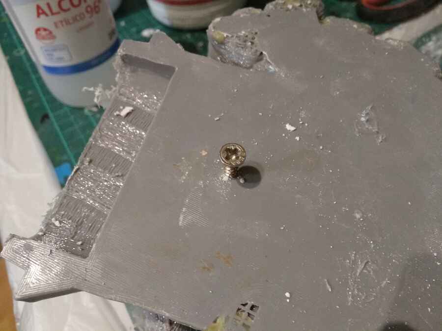
Apply the Algacat (alginate), the plaster pull out the print, I use screws to help plluing it out..
A quick timelapse showing how
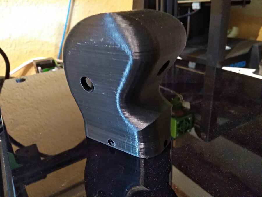
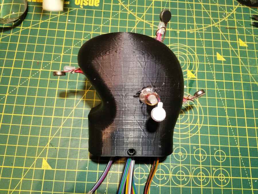
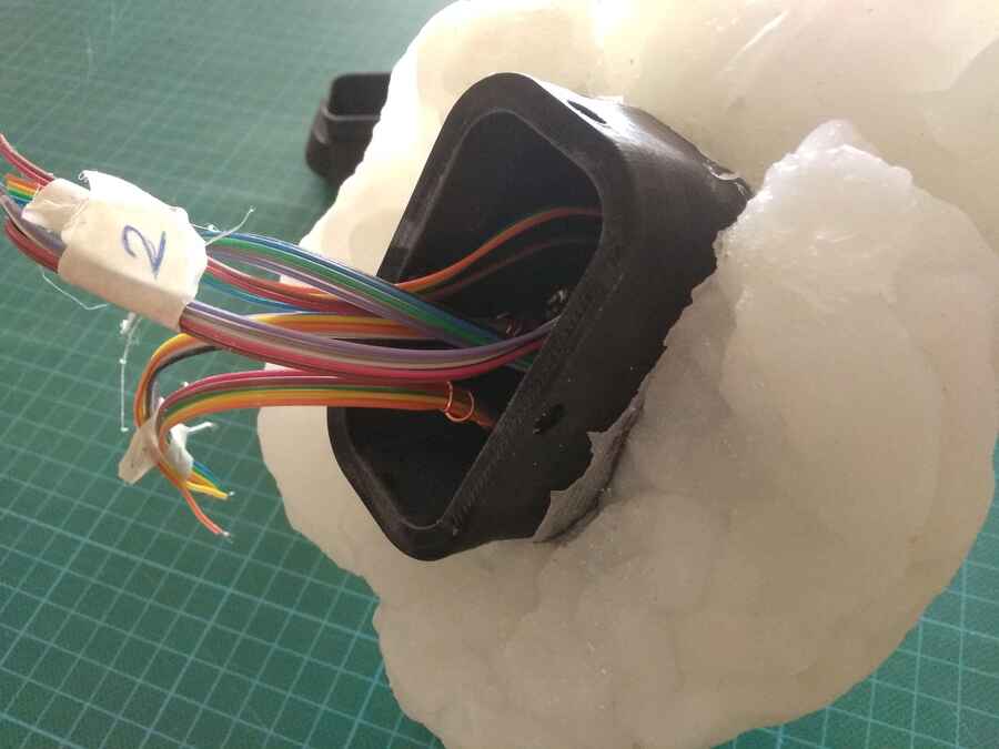
Then I have to prepare the "neck" (3d printed inside rigid part)...
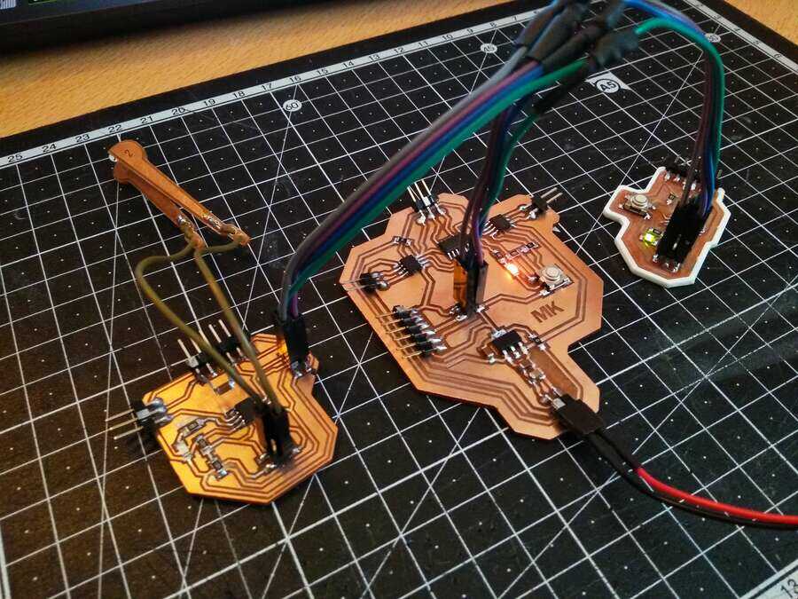
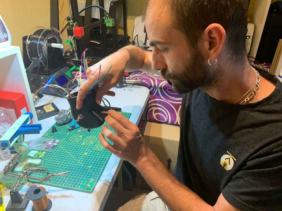
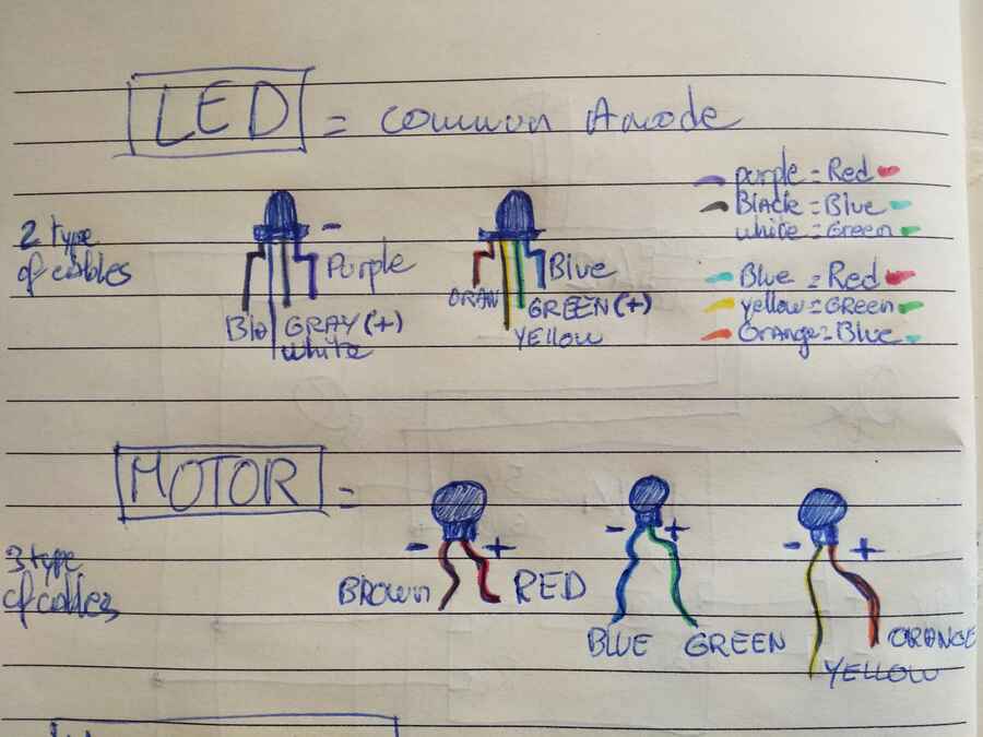
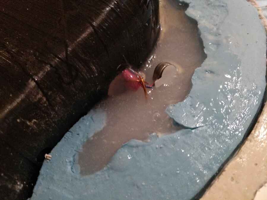
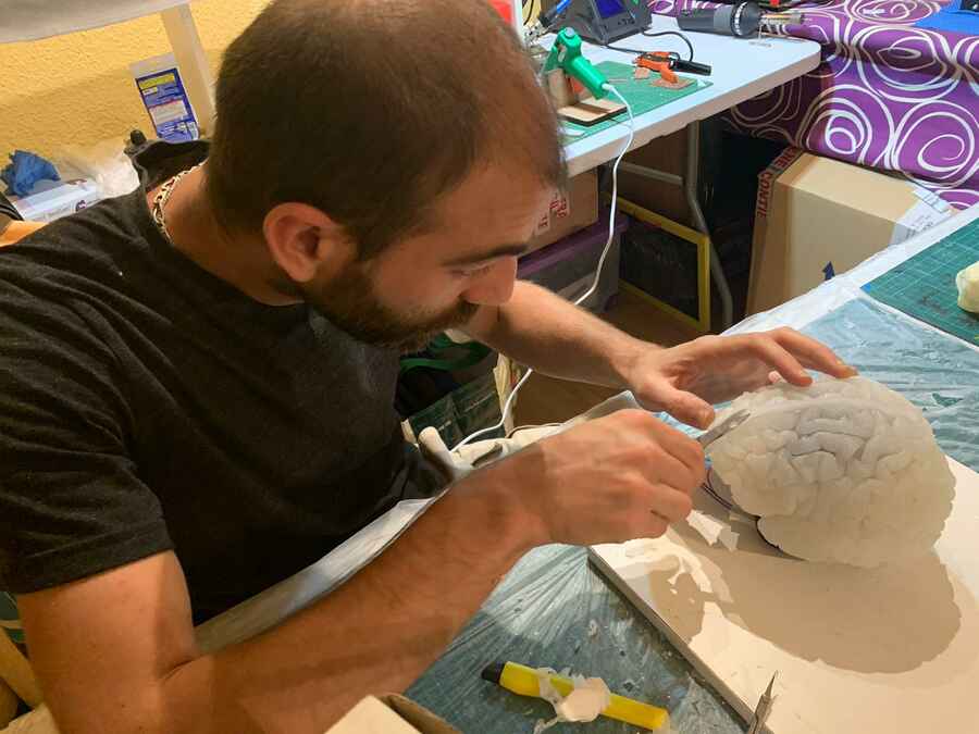
So I am preparing the motors (x5) and the RGB LED (x5) to be casted in the silicon (brain), I used a thin wire and hot glue to hep keeping it inplace.
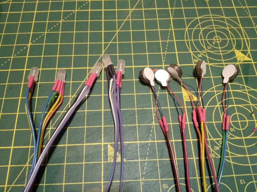
Here is a little reminder so I know how the polarity and pins correspond to the cable colors. I know it will be usefull further on...
Location.
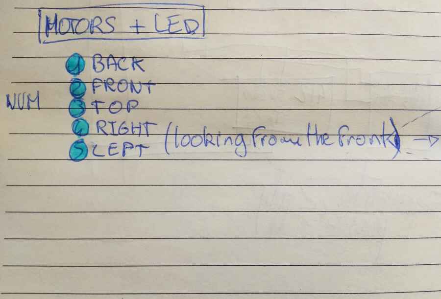
Pins to cable colors
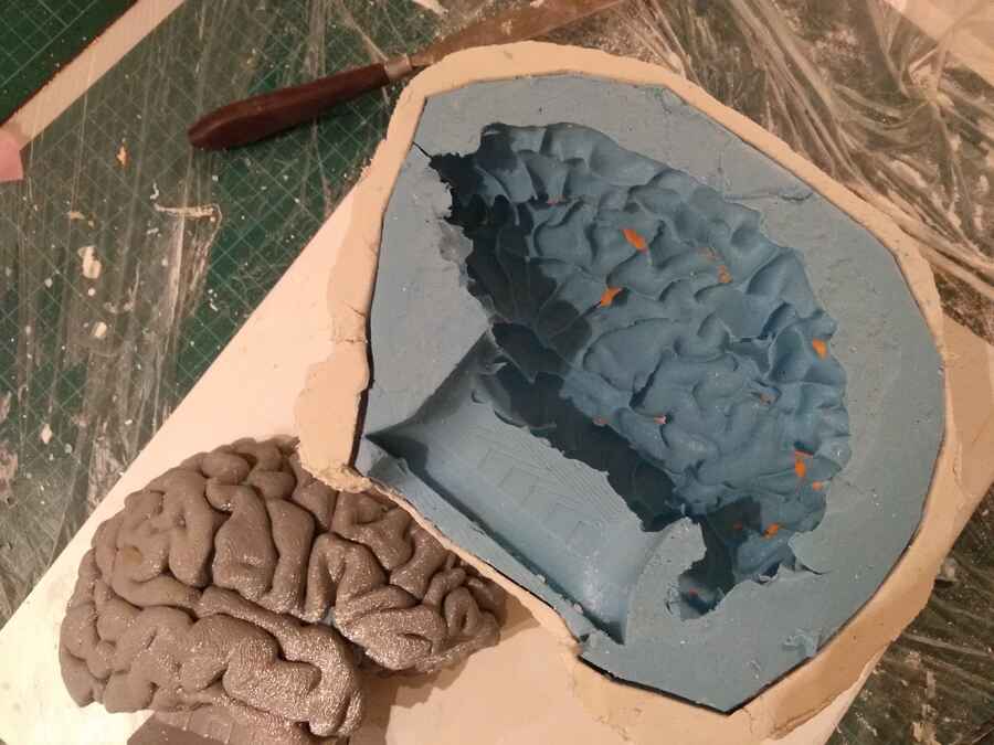
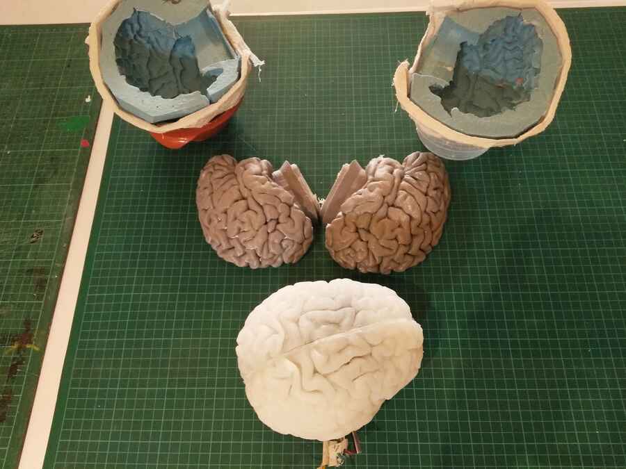
Preparing for the casting of the first side.
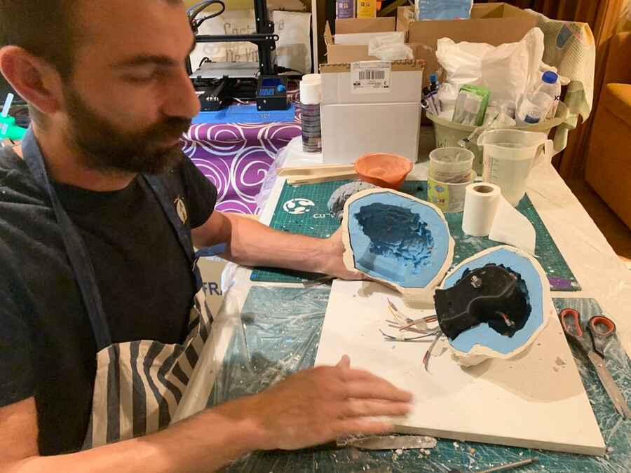
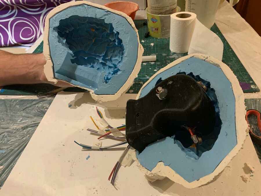
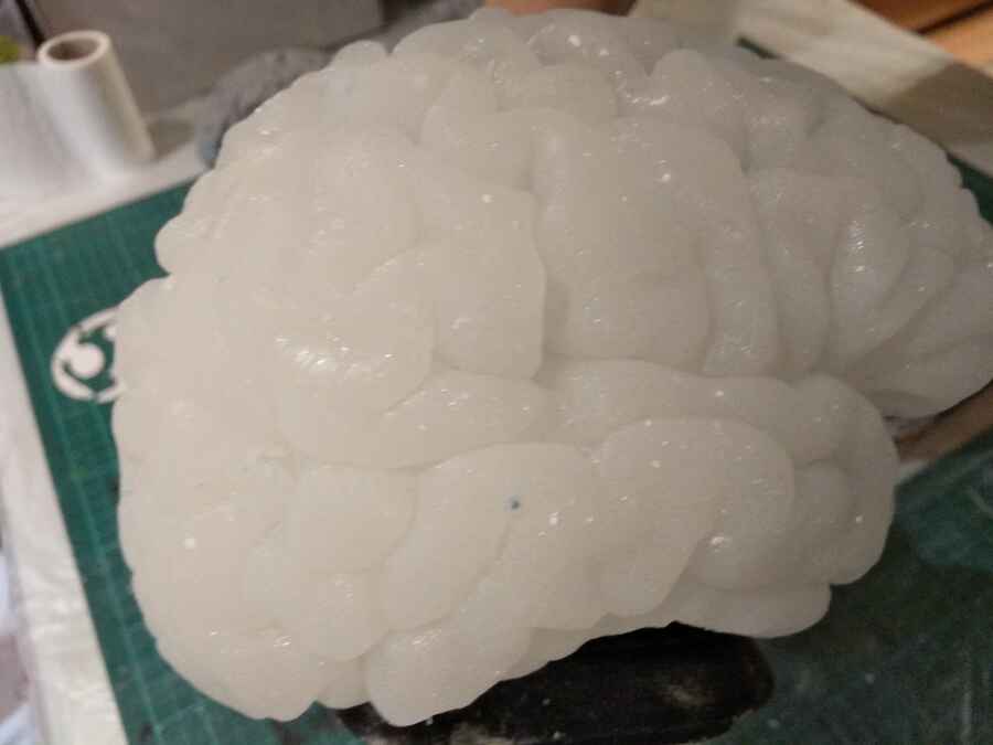
I pour the silicon and wait for it to set...

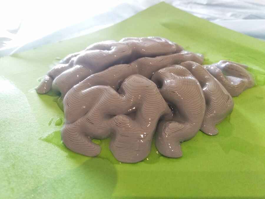
Here is the result of the fist side
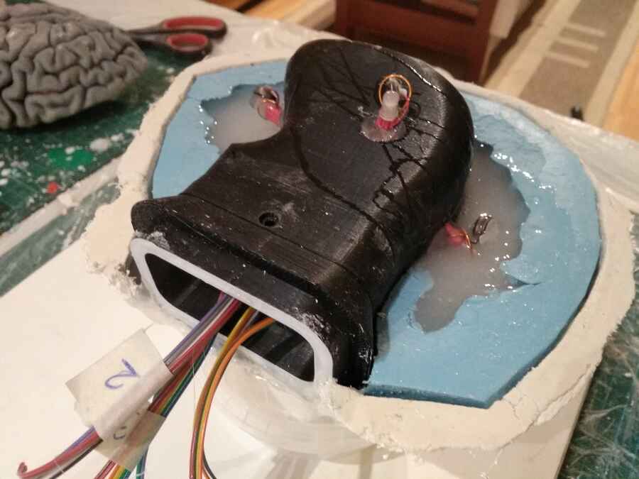
Without losing too much time, I am pouring the second side...
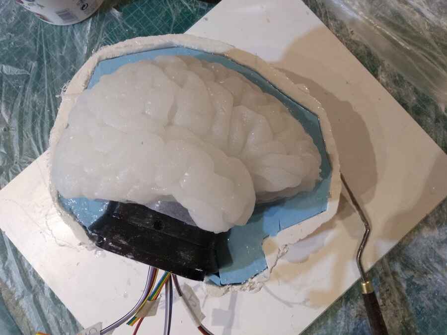
And the result...
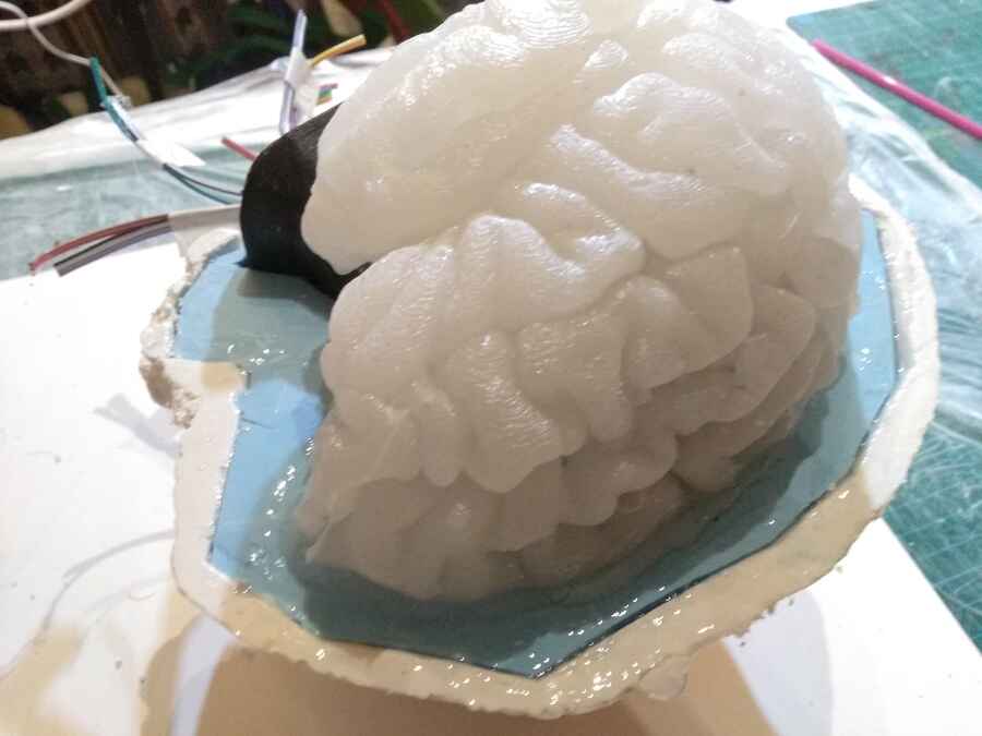
I am triming and cleaning up a little...

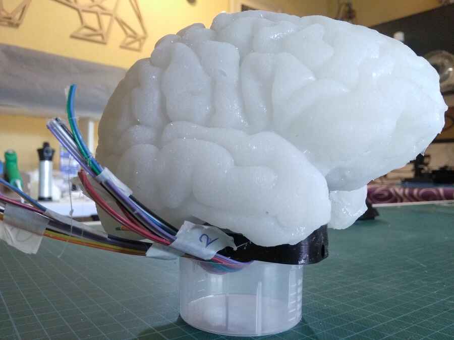
This is how it tourned out... so far, so good.

And the tools for the full process...
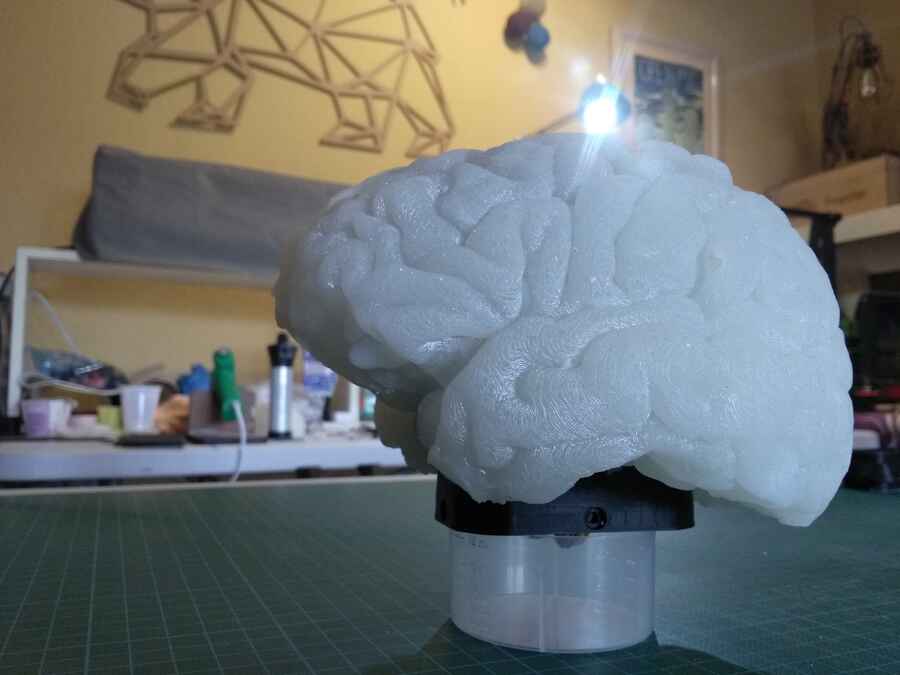
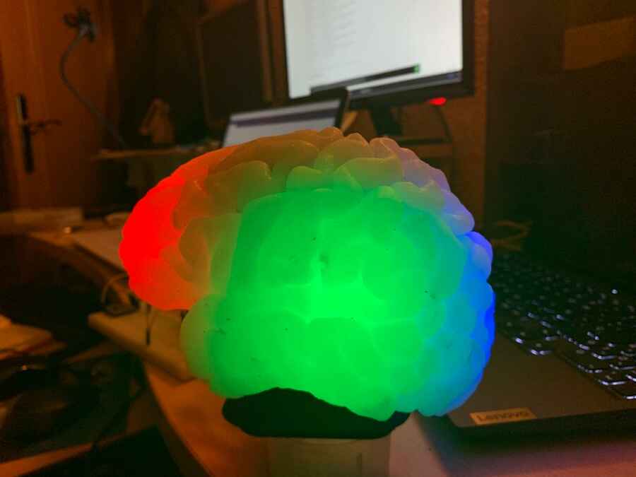
Here is a quick video testing the LEDs...
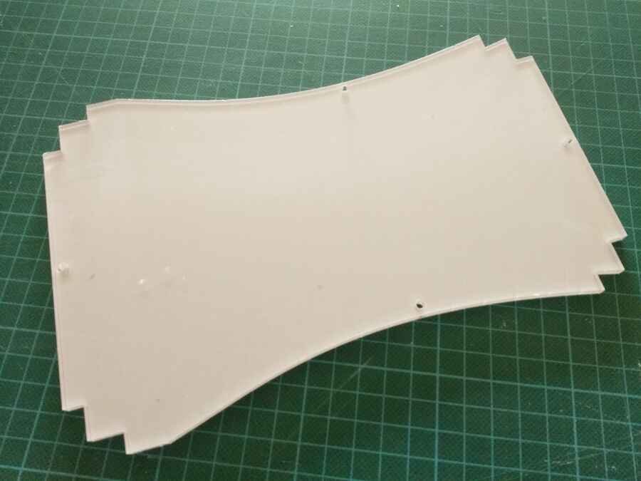
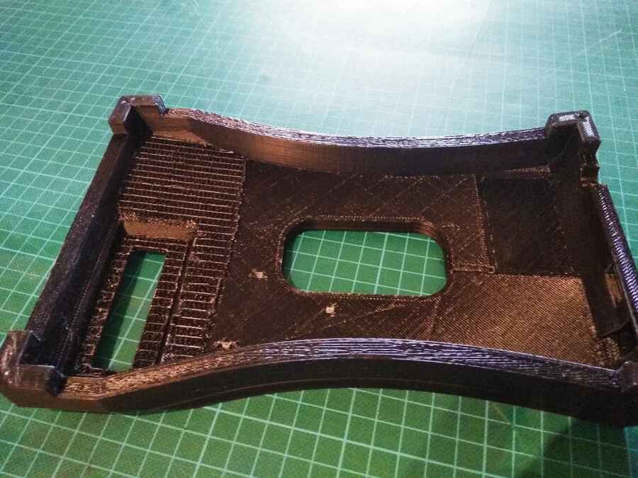
I have also cut the cover acrilic plate for the bottom of the base that I am also printing at the moment...

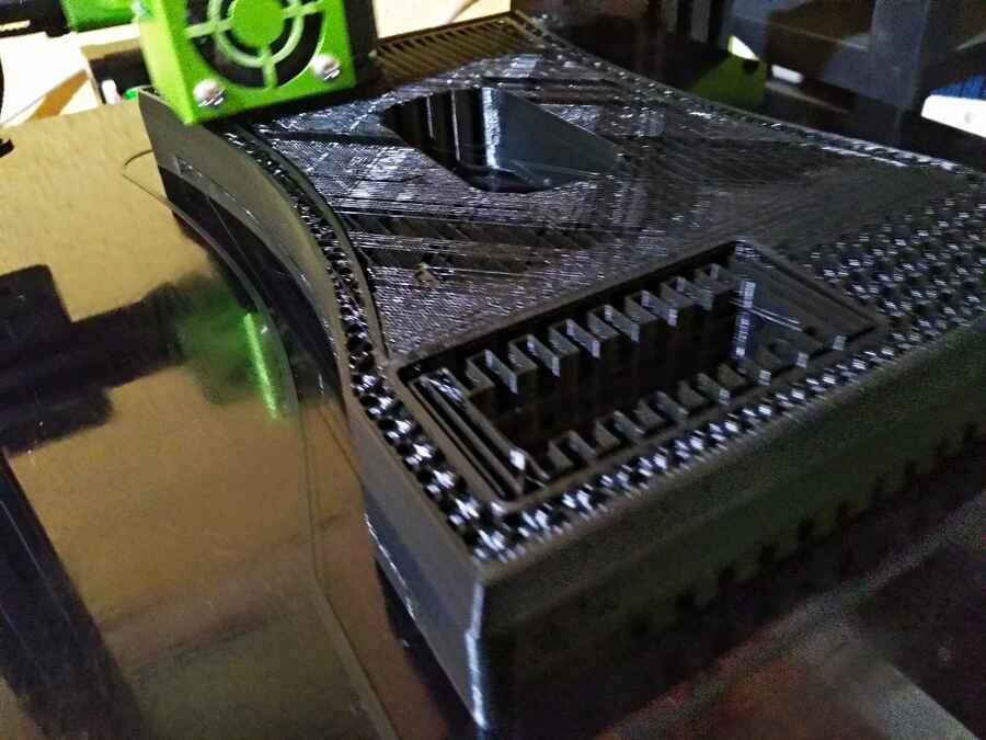
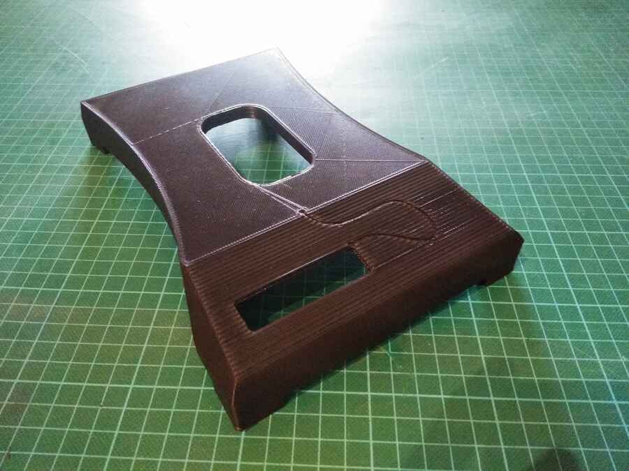
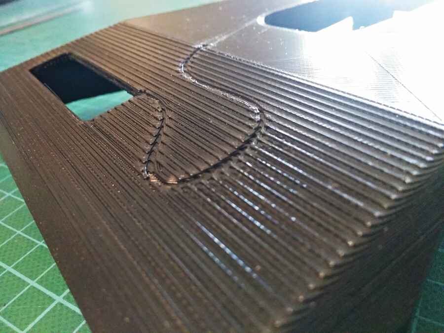
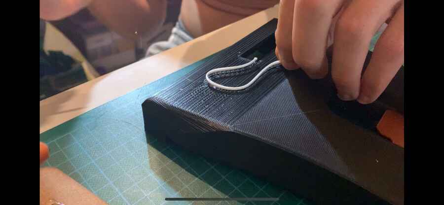
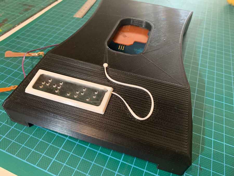
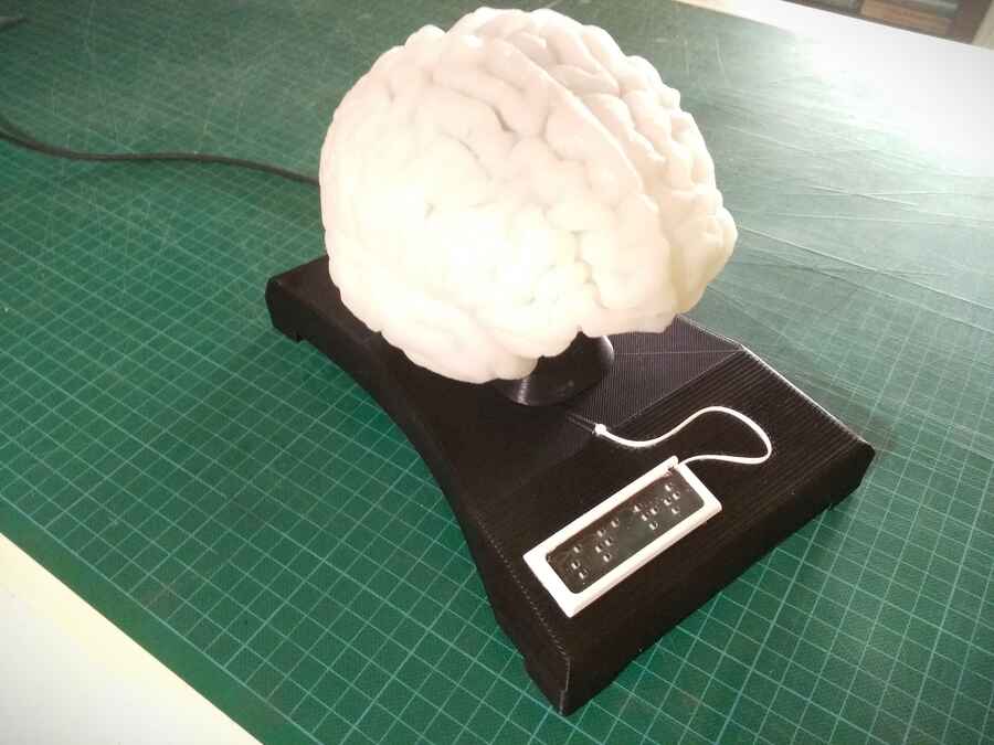
Here is the finished base, its better than expected except for the front, I did expect to have steps but the curve I made for the user to find the model does not feel very clear/clean...I may fill it up with something, also the roof support came off fairly easilly except for the angled part, it is complitly fused. It is a little hugly but does not affect my plan right now so, happydays!!!...
Week18 - Project development
Final project development list:Introduction Week2 - Computer-aided design week8 - Embedded programing Week10 - Input devices Week11 - Molding and Casting Week12 - Output device Week13 - Networking and communications Week16 - Applications and implications Week17 - invention, intellectual property, and income Week18 - Project development
This week I am working on finishing last small peices to mount all the parts together...
I am also getting the audio track ready...To do that I find this great text to voice web app, ttsmp3 has different type of voice to choose from and the track can dirrectly be dowloaded as mp3 format.
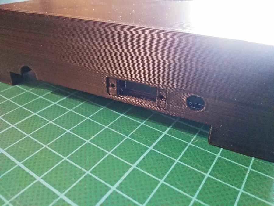
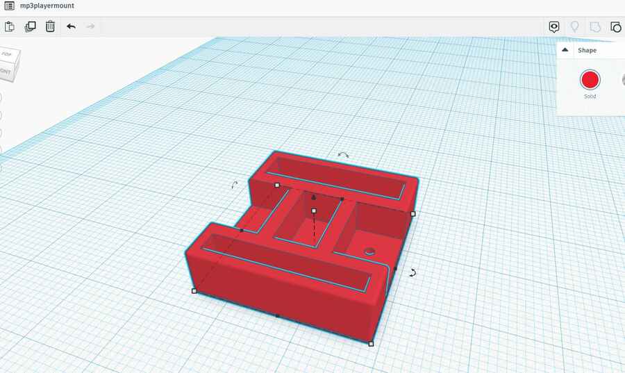
The last 3d prints are just small part that I designed for the front panel (I did not like last week´s results).
...and a part that will help keeping the MP3 player in place
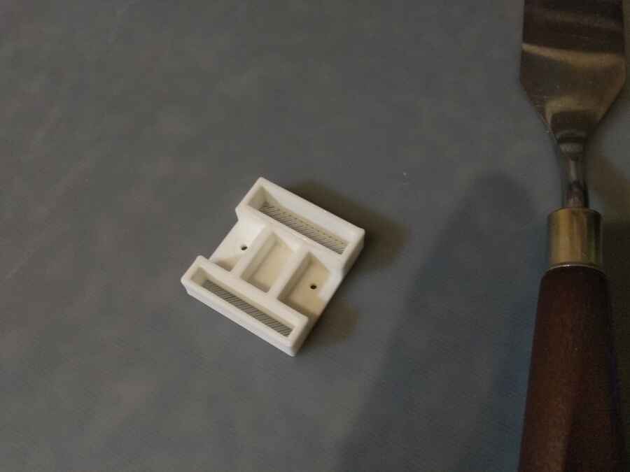
So far, much better...
To mount the electronics, I have made a few board holder with a cable tie and screws to keep them from moving around..
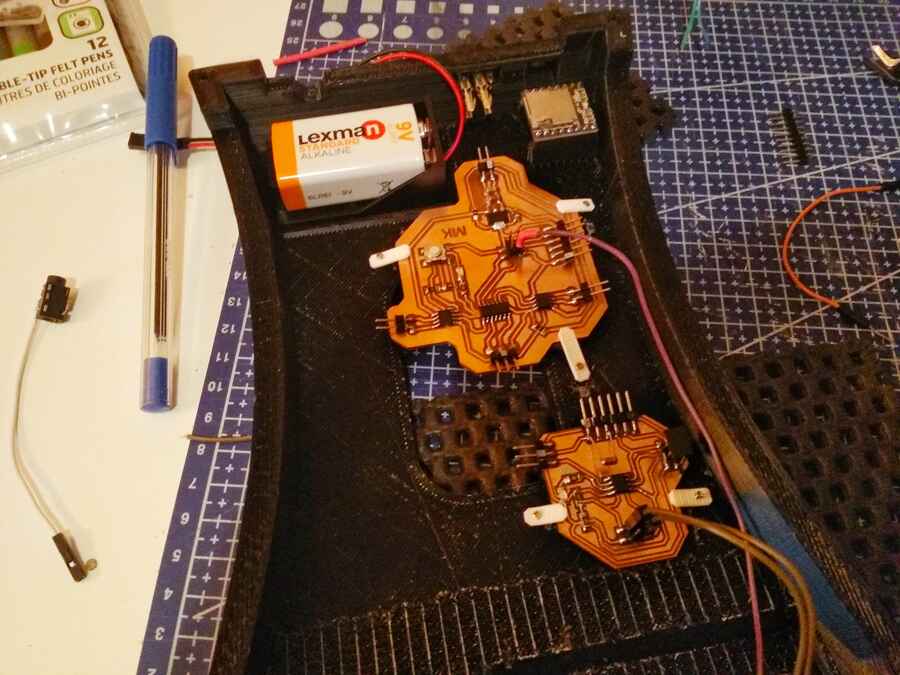
My first attempt was to have the 412 (stepresponse) communicating with the 1614 (motors) and the arduino mini (MP3 player). That did not work...I think the MP3 player does not like to share the network for some reason...On top of that, I have also burned out my step response board....
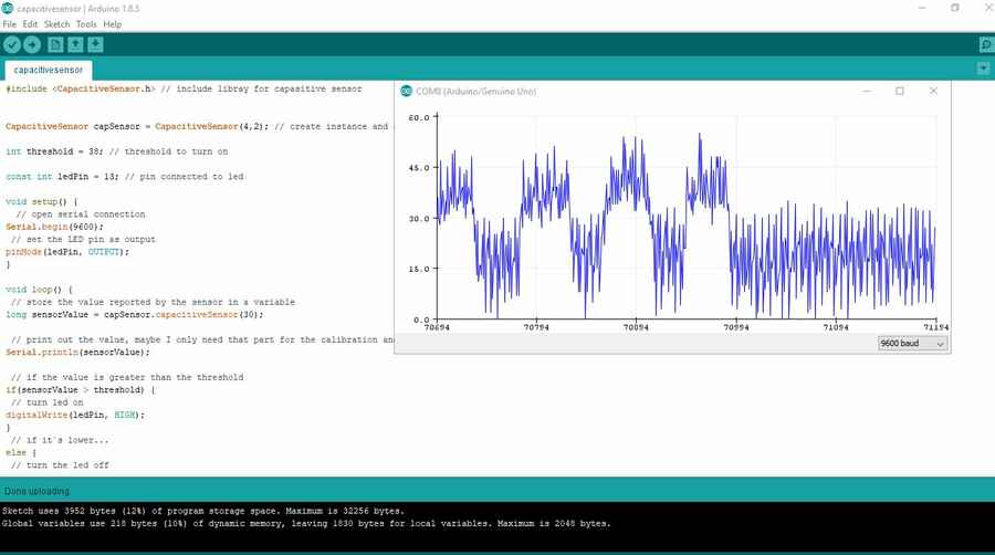
So, after fixing the step response board, instead what I am doing is to separate the step response and motors from the arduino and MP3 player. I find this usefull capacitive sensor library that I will use for to trigger the arduino. Here is a tutorial as example.
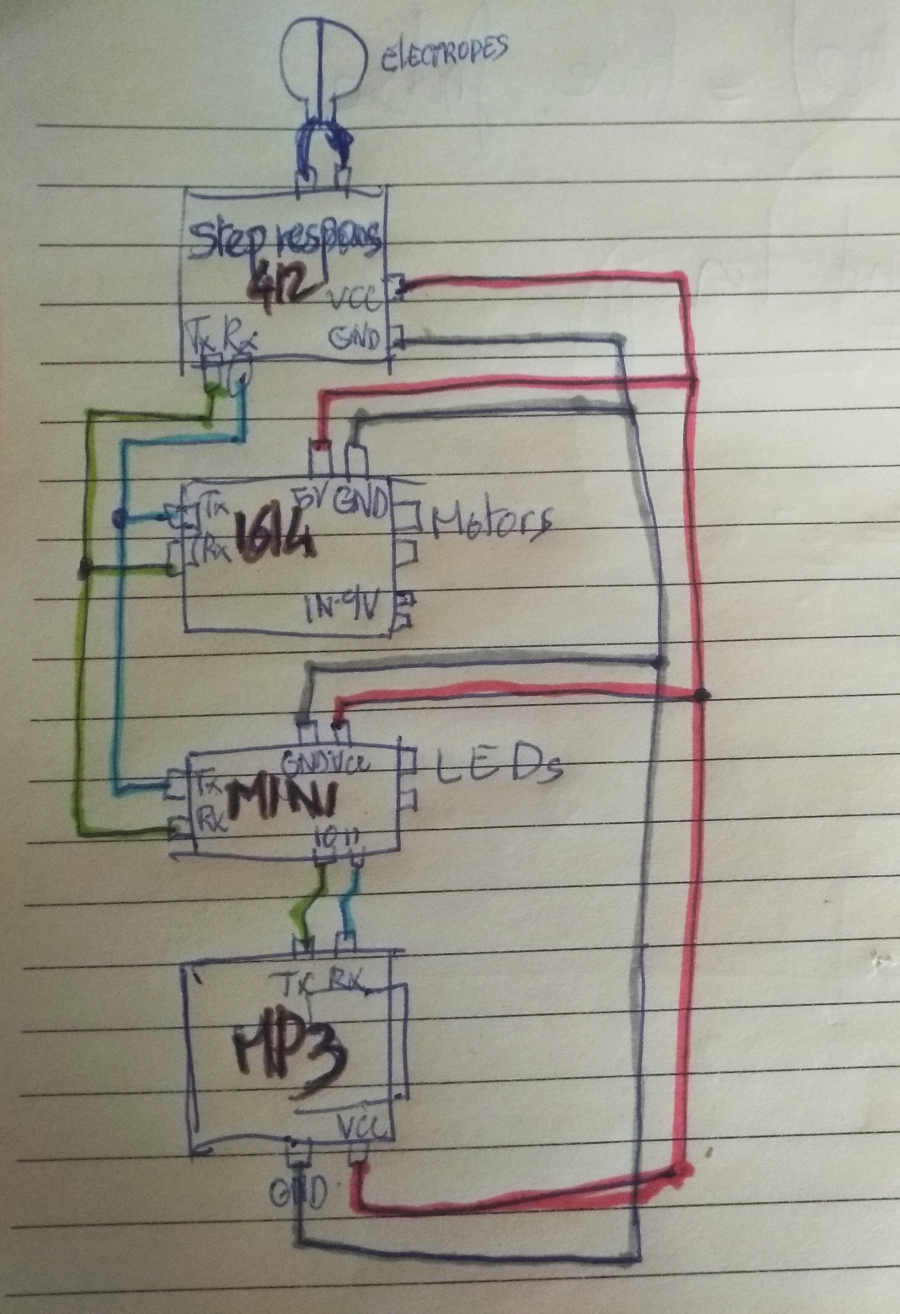
I am hoping to use the step response and arduino as triggers, once the thresholed is passed, a to "A" (1614 nodes) is send through the Tx pin by the 412 board. In the meantime, the arduino mini tells the MP3 player to play the track (0001). The arduino also controls the left and right LEDs now. While the introduction is beeing played, node "A" waits, when the time is right (determined by the code), it starts its routing with the motors.
Calibrating the stepresponse and capacitive sensor was a bit of a nightmare, everytime you plug or unplug a cable the range changes. I finally manage to find a happy medium...
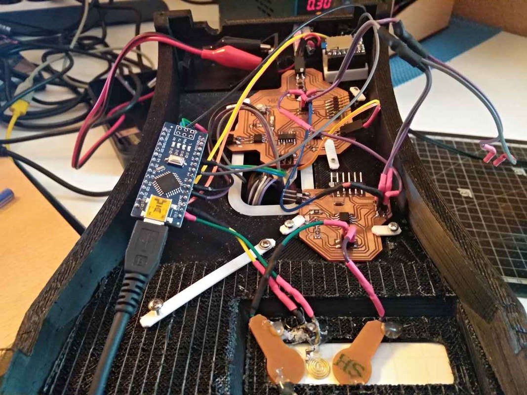
I have to do some cable management but after fighting with wires for a while, it seems to be working fine for now...I have also burned my 1614, not once but twice, just to make things more interesting. I think all the pluging unpluging I do while programing and reading the board is not very healthy...
Here is a video showing the systhem working, I am using headphone as speakers for now as I have no TIME to make a pair. It is hard to hear the motors but if you listen closely...
Here is a quick test to see what the LEDs would look like in the next spiral...
Here are the code, I used so far, the capacitive sensor and step response are triggered at the same time. Both network have a routine to follow. Into with voice, since I added the left and right LEDs, when the voice start explaining the left hemisphere the motors also starts and again when the voice explain the right hemisphere, the LEDS and motors, indicates the area..
For the stepresponse and motor controler...
							//tx_rx03  Robert Hart Mar 2019.

							//ATtiny412

							//  Program to use transmit-receive across space between two conductors.
							//  One conductor attached to digital pin, another to analog pin.
							//
							//  This program has a function "tx_rx() which returns the value in a long integer.
							//
							//  Optionally, two resistors (1 MOhm or greater) can be placed between 5V and GND, with
							//  the signal connected between them so that the steady-state voltage is 2.5 Volts.
							//
							//  Signal varies with electric field coupling between conductors, and can
							//  be used to measure many things related to position, overlap, and intervening material
							//  between the two conductors.
							//


							long result;   //variable for the result of the tx_rx measurement.
							int analog_pin = 2;  //PA1
							int tx_pin = 3;  //PA2
							int threshold = 1680;
							const int ledPin = 4;

							void setup() {
							  pinMode(ledPin, OUTPUT);
							  pinMode(tx_pin, OUTPUT); //Pin 3 provides the voltage step
							  Serial.begin(9600);
							}
							long tx_rx() {        //Function to execute rx_tx algorithm and return a value
							  //that depends on coupling of two electrodes.
							  //Value returned is a long integer.
							  int read_high;
							  int read_low;
							  int diff;
							  long int sum;
							  int N_samples = 80;  //Number of samples to take. Larger number slows it down, but reduces scatter.

							  sum = 0;

							  for (int i = 0; i < N_samples; i++) {
								digitalWrite(tx_pin, HIGH);         //Step the voltage high on conductor 1.
								read_high = analogRead(analog_pin);   //Measure response of conductor 2.
								delayMicroseconds(100);            //Delay to reach steady state.
								digitalWrite(tx_pin, LOW);              //Step the voltage to zero on conductor 1.
								read_low = analogRead(analog_pin);    //Measure response of conductor 2.
								diff = read_high - read_low;   //desired answer is the difference between high and low.
								sum += diff;             //Sums up N_samples of these measurements.
							  }
							  return sum;
							}                   //End of tx_rx function.


							void loop() {

							  result = tx_rx();
							  //result = map(result, 328, 97740, 0, 680);
							  Serial.println(result);
							  delay(50);

							  if (result < threshold)  {
								Serial.println('a');
								delay(10);
								Serial.println('b');
								digitalWrite(ledPin, HIGH);
								delay(200);
								digitalWrite(ledPin, LOW);
								delay(2000);
								digitalWrite(ledPin, HIGH);
								delay(200);
								digitalWrite(ledPin, LOW);

							  }

							  else
								digitalWrite(ledPin, LOW);

							}
Motor controler (1614)
#define in1 0
#define in2 1
#define in3 6
#define in4 7
#define ledpin 10


char nodo = 'b';  //name of this node

void setup() {
  // put your setup code here, to run once:
  Serial.begin (9600); //incializa la comunicacion por serial
  pinMode(in1, OUTPUT);
  pinMode(in2, OUTPUT);
  pinMode(in3, OUTPUT);
  pinMode(in4, OUTPUT);
  pinMode(ledpin, OUTPUT);

}

void loop() {
  // put your main code here, to run repeatedly:
  if (Serial.read() == nodo){
    delay(18000);
    digitalWrite(in3, HIGH);  // turn led and motor RIGHT on/off
    digitalWrite(in4, LOW);
    digitalWrite(ledpin, HIGH);
    delay(200);
    digitalWrite(in3, HIGH);
    digitalWrite(in4, HIGH);
    digitalWrite(ledpin, LOW);
    delay(200);
    digitalWrite(in3, HIGH);  // turn led and motor RIGHT on/off
    digitalWrite(in4, LOW);
    digitalWrite(ledpin, HIGH);
    delay(200);
    digitalWrite(in3, HIGH);
    digitalWrite(in4, HIGH);
    digitalWrite(ledpin, LOW);
    delay(200);
    digitalWrite(in3, HIGH);  // turn led and motor RIGHT on/off
    digitalWrite(in4, LOW);
    digitalWrite(ledpin, HIGH);
    delay(200);
    digitalWrite(in3, HIGH);
    digitalWrite(in4, HIGH);
    digitalWrite(ledpin, LOW);
    delay(200);
    digitalWrite(in3, HIGH);  // turn led and motor RIGHT on/off
    digitalWrite(in4, LOW);
    digitalWrite(ledpin, HIGH);
    delay(200);
    digitalWrite(in3, HIGH);
    digitalWrite(in4, HIGH);
    digitalWrite(ledpin, LOW);
    delay(200);
    digitalWrite(in3, HIGH);  // turn led and motor RIGHT on/off
    digitalWrite(in4, LOW);
    digitalWrite(ledpin, HIGH);
    delay(200);
    digitalWrite(in3, HIGH);
    digitalWrite(in4, HIGH);
    digitalWrite(ledpin, LOW);
    delay(200);
    digitalWrite(in3, HIGH);  // turn led and motor RIGHT on/off
    digitalWrite(in4, LOW);
    digitalWrite(ledpin, HIGH);
    delay(200);
    digitalWrite(in3, HIGH);
    digitalWrite(in4, HIGH);
    digitalWrite(ledpin, LOW);
    delay(200);
    digitalWrite(in3, HIGH);  // turn led and motor RIGHT on/off
    digitalWrite(in4, LOW);
    digitalWrite(ledpin, HIGH);
    delay(200);
    digitalWrite(in3, HIGH);
    digitalWrite(in4, HIGH);
    digitalWrite(ledpin, LOW);
    delay(200);
    digitalWrite(in3, HIGH);  // turn led and motor RIGHT on/off
    digitalWrite(in4, LOW);
    digitalWrite(ledpin, HIGH);
    delay(200);
    digitalWrite(in3, HIGH);
    digitalWrite(in4, HIGH);
    digitalWrite(ledpin, LOW);
    delay(200);
    digitalWrite(in3, HIGH);  // turn led and motor RIGHT on/off
    digitalWrite(in4, LOW);
    digitalWrite(ledpin, HIGH);
    delay(200);
    digitalWrite(in3, HIGH);
    digitalWrite(in4, HIGH);
    digitalWrite(ledpin, LOW);
    delay(200);
    digitalWrite(in3, HIGH);  // turn led and motor RIGHT on/off
    digitalWrite(in4, LOW);
    digitalWrite(ledpin, HIGH);
    delay(200);
    digitalWrite(in3, HIGH);
    digitalWrite(in4, HIGH);
    digitalWrite(ledpin, LOW);
    delay(200);
    digitalWrite(in3, HIGH);  // turn led and motor RIGHT on/off
    digitalWrite(in4, LOW);
    digitalWrite(ledpin, HIGH);
    delay(200);
    digitalWrite(in3, HIGH);
    digitalWrite(in4, HIGH);
    digitalWrite(ledpin, LOW);
    delay(200);
    digitalWrite(in3, HIGH);  // turn led and motor RIGHT on/off
    digitalWrite(in4, LOW);
    digitalWrite(ledpin, HIGH);
    delay(200);
    digitalWrite(in3, HIGH);
    digitalWrite(in4, HIGH);
    digitalWrite(ledpin, LOW);
    delay(200);
    digitalWrite(in3, HIGH);  // turn led and motor RIGHT on/off
    digitalWrite(in4, LOW);
    digitalWrite(ledpin, HIGH);
    delay(200);
    digitalWrite(in3, HIGH);
    digitalWrite(in4, HIGH);
    digitalWrite(ledpin, LOW);
    delay(200);
    digitalWrite(in3, HIGH);  // turn led and motor RIGHT on/off
    digitalWrite(in4, LOW);
    digitalWrite(ledpin, HIGH);
    delay(200);
    digitalWrite(in3, HIGH);
    digitalWrite(in4, HIGH);
    digitalWrite(ledpin, LOW);
    delay(200);
    digitalWrite(in3, HIGH);  // turn led and motor RIGHT on/off
    digitalWrite(in4, LOW);
    digitalWrite(ledpin, HIGH);
    delay(200);
    digitalWrite(in3, HIGH);
    digitalWrite(in4, HIGH);
    digitalWrite(ledpin, LOW);
    delay(200);
    digitalWrite(in3, HIGH);  // turn led and motor RIGHT on/off
    digitalWrite(in4, LOW);
    digitalWrite(ledpin, HIGH);
    delay(200);
    digitalWrite(in3, HIGH);
    digitalWrite(in4, HIGH);
    digitalWrite(ledpin, LOW);
    delay(10500);
    digitalWrite(in1, HIGH);  // turn led and motor LEFT on/off
    digitalWrite(in2, LOW);
    digitalWrite(ledpin, HIGH);
    delay(200);
    digitalWrite(in1, HIGH);
    digitalWrite(in2, HIGH);
    digitalWrite(ledpin, LOW);
    delay(200);
    digitalWrite(in1, HIGH);  // turn led and motor LEFT on/off
    digitalWrite(in2, LOW);
    digitalWrite(ledpin, HIGH);
    delay(200);
    digitalWrite(in1, HIGH);
    digitalWrite(in2, HIGH);
    digitalWrite(ledpin, LOW);
    delay(200);
    digitalWrite(in1, HIGH);  // turn led and motor LEFT on/off
    digitalWrite(in2, LOW);
    digitalWrite(ledpin, HIGH);
    delay(200);
    digitalWrite(in1, HIGH);
    digitalWrite(in2, HIGH);
    digitalWrite(ledpin, LOW);
    delay(200);
    digitalWrite(in1, HIGH);  // turn led and motor LEFT on/off
    digitalWrite(in2, LOW);
    digitalWrite(ledpin, HIGH);
    delay(200);
    digitalWrite(in1, HIGH);
    digitalWrite(in2, HIGH);
    digitalWrite(ledpin, LOW);
    delay(200);
    digitalWrite(in1, HIGH);  // turn led and motor LEFT on/off
    digitalWrite(in2, LOW);
    digitalWrite(ledpin, HIGH);
    delay(200);
    digitalWrite(in1, HIGH);
    digitalWrite(in2, HIGH);
    digitalWrite(ledpin, LOW);
    delay(200);
    digitalWrite(in1, HIGH);  // turn led and motor LEFT on/off
    digitalWrite(in2, LOW);
    digitalWrite(ledpin, HIGH);
    delay(200);
    digitalWrite(in1, HIGH);
    digitalWrite(in2, HIGH);
    digitalWrite(ledpin, LOW);
    delay(200);
    digitalWrite(in1, HIGH);  // turn led and motor LEFT on/off
    digitalWrite(in2, LOW);
    digitalWrite(ledpin, HIGH);
    delay(200);
    digitalWrite(in1, HIGH);
    digitalWrite(in2, HIGH);
    digitalWrite(ledpin, LOW);
    delay(200);
    digitalWrite(in1, HIGH);  // turn led and motor LEFT on/off
    digitalWrite(in2, LOW);
    digitalWrite(ledpin, HIGH);
    delay(200);
    digitalWrite(in1, HIGH);
    digitalWrite(in2, HIGH);
    digitalWrite(ledpin, LOW);
    delay(200);
    digitalWrite(in1, HIGH);  // turn led and motor LEFT on/off
    digitalWrite(in2, LOW);
    digitalWrite(ledpin, HIGH);
    delay(200);
    digitalWrite(in1, HIGH);
    digitalWrite(in2, HIGH);
    digitalWrite(ledpin, LOW);
    delay(200);
    digitalWrite(in1, HIGH);  // turn led and motor LEFT on/off
    digitalWrite(in2, LOW);
    digitalWrite(ledpin, HIGH);
    delay(200);
    digitalWrite(in1, HIGH);
    digitalWrite(in2, HIGH);
    digitalWrite(ledpin, LOW);
    delay(200);
    digitalWrite(in1, HIGH);  // turn led and motor LEFT on/off
    digitalWrite(in2, LOW);
    digitalWrite(ledpin, HIGH);
    delay(200);
    digitalWrite(in1, HIGH);
    digitalWrite(in2, HIGH);
    digitalWrite(ledpin, LOW);
    delay(200);
    digitalWrite(in1, HIGH);  // turn led and motor LEFT on/off
    digitalWrite(in2, LOW);
    digitalWrite(ledpin, HIGH);
    delay(200);
    digitalWrite(in1, HIGH);
    digitalWrite(in2, HIGH);
    digitalWrite(ledpin, LOW);
    delay(200);
    digitalWrite(in1, HIGH);  // turn led and motor LEFT on/off
    digitalWrite(in2, LOW);
    digitalWrite(ledpin, HIGH);
    delay(200);
    digitalWrite(in1, HIGH);
    digitalWrite(in2, HIGH);
    digitalWrite(ledpin, LOW);
    delay(200);
    digitalWrite(in1, HIGH);  // turn led and motor LEFT on/off
    digitalWrite(in2, LOW);
    digitalWrite(ledpin, HIGH);
    delay(200);
    digitalWrite(in1, HIGH);
    digitalWrite(in2, HIGH);
    digitalWrite(ledpin, LOW);
    delay(200);
    digitalWrite(in1, HIGH);  // turn led and motor LEFT on/off
    digitalWrite(in2, LOW);
    digitalWrite(ledpin, HIGH);
    delay(200);
    digitalWrite(in1, HIGH);
    digitalWrite(in2, HIGH);
    digitalWrite(ledpin, LOW);
    delay(200);
    digitalWrite(in1, HIGH);  // turn led and motor LEFT on/off
    digitalWrite(in2, LOW);
    digitalWrite(ledpin, HIGH);
    delay(200);
    digitalWrite(in1, HIGH);
    digitalWrite(in2, HIGH);
    digitalWrite(ledpin, LOW);
    delay(200);
}
else  {
digitalWrite(ledpin, LOW);    // turn the LED off by making the voltage LOW
delay(10);
}
}
While the stepresponse and motor controler does their thing, the arduino and MP3 player that was triggered at the same time, also have their own routine...
/***************************************************
DFPlayer - A Mini MP3 Player For Arduino
Created 2016-12-07 by [Angelo qiao](Angelo.qiao@dfrobot.com)
GNU Lesser General Public License.
See
2.This code is tested on Arduino Uno, Leonardo, Mega boards.
/****************************************************/
#include "Arduino.h"
#include "SoftwareSerial.h"
#include "DFRobotDFPlayerMini.h"
#include // include libray for capasitive sensor
CapacitiveSensor capSensor = CapacitiveSensor(A1,A0); // create instance and assign pin4 sends energy,
// pin2, senses the change
SoftwareSerial mySoftwareSerial(10, 11); // communication for the mp3 player Rx, Tx
DFRobotDFPlayerMini myDFPlayer; // MP3 player object
void printDetail(uint8_t type, int value);
int threshold = 20; // threshold to turn on
const int ledPin = 13; // pin connected to on board led
const int ledPin2 = A4; // pin led left
const int ledPin3 = A5; // pin led right
void setup()
{
mySoftwareSerial.begin(9600);
Serial.begin(9600);
pinMode(ledPin, OUTPUT);
pinMode(ledPin2, OUTPUT);
pinMode(ledPin3, OUTPUT);
Serial.println();
Serial.println(F("DFRobot DFPlayer Mini Demo"));
Serial.println(F("Initializing DFPlayer ... (May take 3~5 seconds)"));
if (!myDFPlayer.begin(mySoftwareSerial)) { //Use softwareSerial to communicate with mp3.
Serial.println(F("Unable to begin:"));
Serial.println(F("1.Please recheck the connection!"));
Serial.println(F("2.Please insert the SD card!"));
while(true);
}
Serial.println(F("DFPlayer Mini online."));
myDFPlayer.setTimeOut(500); //Set serial communictaion time out 500ms
//----Set volume----
myDFPlayer.volume(15); //Set volume value (0~30).
myDFPlayer.volumeUp(); //Volume Up
myDFPlayer.volumeDown(); //Volume Down
//----Set different EQ----
myDFPlayer.EQ(DFPLAYER_EQ_NORMAL);
//----Set device we use SD as default----
myDFPlayer.outputDevice(DFPLAYER_DEVICE_SD);
//----Mp3 play----
// myDFPlayer.next(); //Play next mp3
// delay(1000);
// myDFPlayer.play(1); //Play the first mp3
// delay(1000);
// myDFPlayer.loop(1); //Loop the first mp3
// delay(1000);
// myDFPlayer.playFolder(15, 4); //play specific mp3 in
//SD:/15/004.mp3; Folder Name(1~99); File Name(1~255)
// delay(1000);
// myDFPlayer.enableLoop(); //enable loop.
// delay(1000);
// myDFPlayer.disableLoop(); //disable loop.
// delay(1000);
//----Read imformation----
Serial.println(myDFPlayer.readState()); //read mp3 state
Serial.println(myDFPlayer.readVolume()); //read current volume
Serial.println(myDFPlayer.readEQ()); //read EQ setting
Serial.println(myDFPlayer.readFileCounts()); //read all file counts in SD card
Serial.println(myDFPlayer.readCurrentFileNumber()); //read current play file number
Serial.println(myDFPlayer.readFileCountsInFolder(3)); //read file counts in folder SD:/03
}
void loop()
{
// store the value reported by the sensor in a variable
long sensorValue = capSensor.capacitiveSensor(25);
// print out the value
Serial.println(sensorValue);
// if the value is greater than the threshold
if(sensorValue > threshold) {
// turn led on and send play to mp3 player
digitalWrite(ledPin, HIGH);
digitalWrite(ledPin2, HIGH); // turn led left on
delay(300);
digitalWrite(ledPin3, HIGH); // turn led right on
delay(300);
digitalWrite(ledPin2, LOW); // turn led left on
delay(300);
digitalWrite(ledPin3, LOW); // turn led right on
delay(300);
myDFPlayer.next();// Send signal to DFPlayer
digitalWrite(ledPin2, HIGH); // turn led left on
delay(300);
digitalWrite(ledPin3, HIGH); // turn led right on
delay(300);
digitalWrite(ledPin2, LOW); // turn led left on
delay(300);
digitalWrite(ledPin3, LOW); // turn led right on
delay(300);
digitalWrite(ledPin2, HIGH); // turn led left on
delay(300);
digitalWrite(ledPin3, HIGH); // turn led right on
delay(300);
digitalWrite(ledPin2, LOW); // turn led left on
delay(300);
digitalWrite(ledPin3, LOW); // turn led right on
delay(300);
digitalWrite(ledPin2, HIGH); // turn led left on
delay(300);
digitalWrite(ledPin3, HIGH); // turn led right on
delay(300);
digitalWrite(ledPin2, LOW); // turn led left on
delay(300);
digitalWrite(ledPin3, LOW); // turn led right on
delay(300);
delay(15000);
////////// RIGHT LED //////////
digitalWrite(ledPin2, HIGH); // turn led left on
delay(100);
digitalWrite(ledPin2, LOW); // turn led right on
delay(100);
digitalWrite(ledPin2, HIGH); // turn led left on
delay(100);
digitalWrite(ledPin2, LOW); // turn led right on
delay(100);
digitalWrite(ledPin2, HIGH); // turn led left on
delay(100);
digitalWrite(ledPin2, LOW); // turn led right on
delay(100);
digitalWrite(ledPin2, HIGH); // turn led left on
delay(100);
digitalWrite(ledPin2, LOW); // turn led right on
delay(2000);
digitalWrite(ledPin2, HIGH); // turn led left on
delay(100);
digitalWrite(ledPin2, LOW); // turn led right on
delay(100);
digitalWrite(ledPin2, HIGH); // turn led left on
delay(100);
digitalWrite(ledPin2, LOW); // turn led right on
delay(100);
digitalWrite(ledPin2, HIGH); // turn led left on
delay(100);
digitalWrite(ledPin2, LOW); // turn led right on
delay(100);
digitalWrite(ledPin2, HIGH); // turn led left on
delay(100);
digitalWrite(ledPin2, LOW); // turn led right on
delay(2000);
////////// LEFT LED //////////
digitalWrite(ledPin3, HIGH); // turn led right on
delay(100);
digitalWrite(ledPin3, LOW); // turn led left on
delay(100);
digitalWrite(ledPin3, HIGH); // turn led right on
delay(100);
digitalWrite(ledPin3, LOW); // turn led left on
delay(100);
digitalWrite(ledPin3, HIGH); // turn led right on
delay(100);
digitalWrite(ledPin3, LOW); // turn led left on
delay(100);
digitalWrite(ledPin3, HIGH); // turn led right on
delay(100);
digitalWrite(ledPin3, LOW); // turn led left on
delay(2000);
digitalWrite(ledPin3, HIGH); // turn led right on
delay(100);
digitalWrite(ledPin3, LOW); // turn led left on
delay(100);
digitalWrite(ledPin3, HIGH); // turn led right on
delay(100);
digitalWrite(ledPin3, LOW); // turn led left on
delay(100);
digitalWrite(ledPin3, HIGH); // turn led right on
delay(100);
digitalWrite(ledPin3, LOW); // turn led left on
delay(100);
digitalWrite(ledPin3, HIGH); // turn led right on
delay(100);
digitalWrite(ledPin3, LOW); // turn led left on
delay(2000);
}
// if not...
else {
// turn the led off
digitalWrite(ledPin, LOW);
digitalWrite(ledPin2, LOW);
digitalWrite(ledPin3, LOW);
}
}
void printDetail(uint8_t type, int value){
switch (type) {
case TimeOut:
Serial.println(F("Time Out!"));
break;
case WrongStack:
Serial.println(F("Stack Wrong!"));
break;
case DFPlayerCardInserted:
Serial.println(F("Card Inserted!"));
break;
case DFPlayerCardRemoved:
Serial.println(F("Card Removed!"));
break;
case DFPlayerCardOnline:
Serial.println(F("Card Online!"));
break;
case DFPlayerUSBInserted:
Serial.println("USB Inserted!");
break;
case DFPlayerUSBRemoved:
Serial.println("USB Removed!");
break;
case DFPlayerPlayFinished:
Serial.print(F("Number:"));
Serial.print(value);
Serial.println(F(" Play Finished!"));
break;
case DFPlayerError:
Serial.print(F("DFPlayerError:"));
switch (value) {
case Busy:
Serial.println(F("Card not found"));
break;
case Sleeping:
Serial.println(F("Sleeping"));
break;
case SerialWrongStack:
Serial.println(F("Get Wrong Stack"));
break;
case CheckSumNotMatch:
Serial.println(F("Check Sum Not Match"));
break;
case FileIndexOut:
Serial.println(F("File Index Out of Bound"));
break;
case FileMismatch:
Serial.println(F("Cannot Find File"));
break;
case Advertise:
Serial.println(F("In Advertise"));
break;
default:
break;
}
break;
default:
break;
}
}
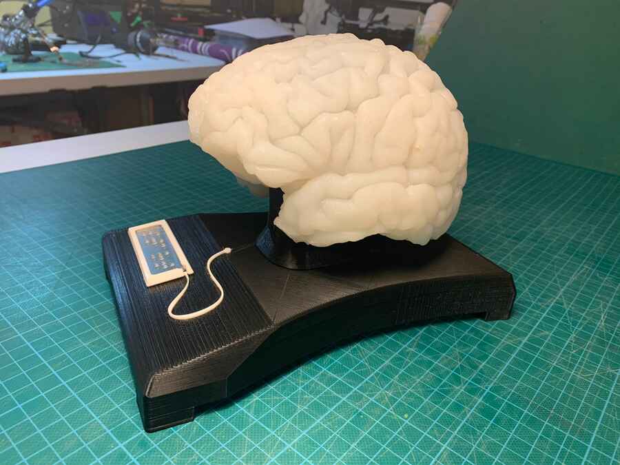
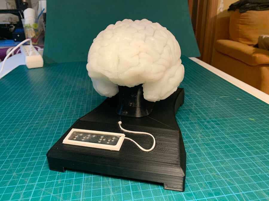
A few shots of the final thingy (unit).
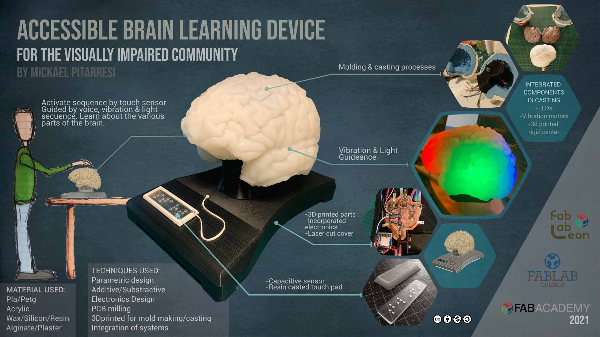
I have also worked on the slide and video for the presentation, here is the final versions...
And ofourse at the last minute I have messed up and had some pending commits that were not allowing me to push the video because of the 10mb limit. Thanks to Pablo, that uploaded the video from is side. With sometime I was able to fix this issues by removing this pending commits that were way over the limit (multiple attempt of video uploading). Here is a great link that help with that issue.
The Slide
And the video...