INTRODUCTION TO AVR MICROCONTROLLER
Microcontroller is the advanced version of microprocessors.A microcontroller is an integrated circuit (IC) device used
for controlling other portions of an electronic system,
usually via a microprocessor unit (MPU), memory, and some peripherals. It contain on chip central processing unit (CPU),
Read only memory (ROM), Random access memory (RAM), input/output unit, interrupts controller etc.
Therefore a microcontroller is used for high speed signal processing operation inside an embedded system.
It acts as major component used in designing of an embedded system.
AVR microcontroller is an electronic chip manufactured by Atmel, which has several advantages over other types of microcontroller.
We can understand microcontroller by comparing it with Personal Computer (PC), which has a motherboard inside it.
In that motherboard a microprocessor (AMD, Intel chips) is used that provides the intelligence,
EEPROM and RAM memories for interfacing to the system like serial ports, display interfaces and disk drivers.
A microcontroller has all or most of these features built into a single chip, therefore it doesn’t require a motherboard and any other components.
AVR microcontroller comes in different configuration, some designed using surface mounting and some designed using whole mounting. It is available with 8-pins to 100-pins, any microcontroller with 64-pin or over is surface mount only.
.ATmega8 microcontroller
.ATmega16 microcontroller
.ATmega32 microcontroller
.ATmega328 microcontroller
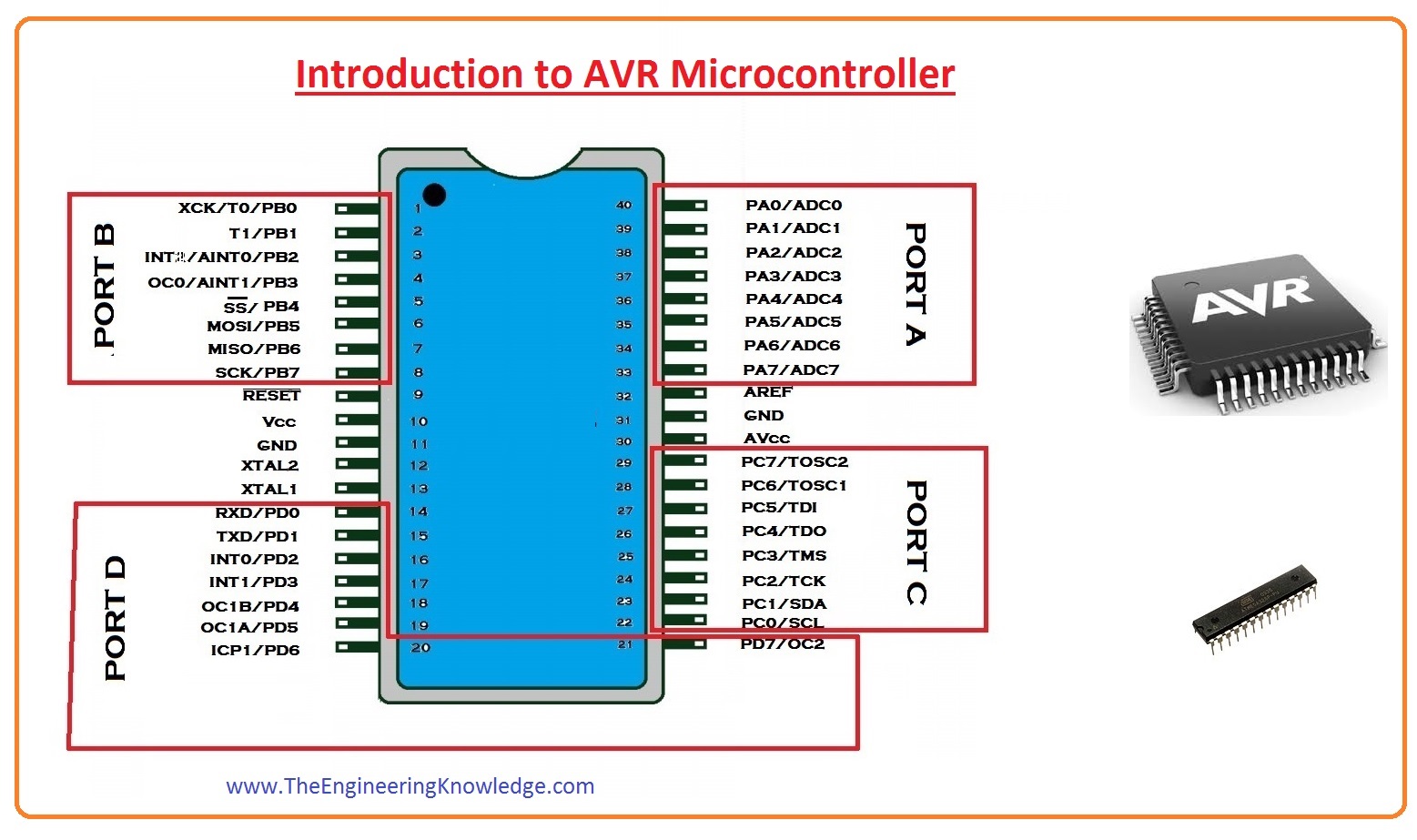
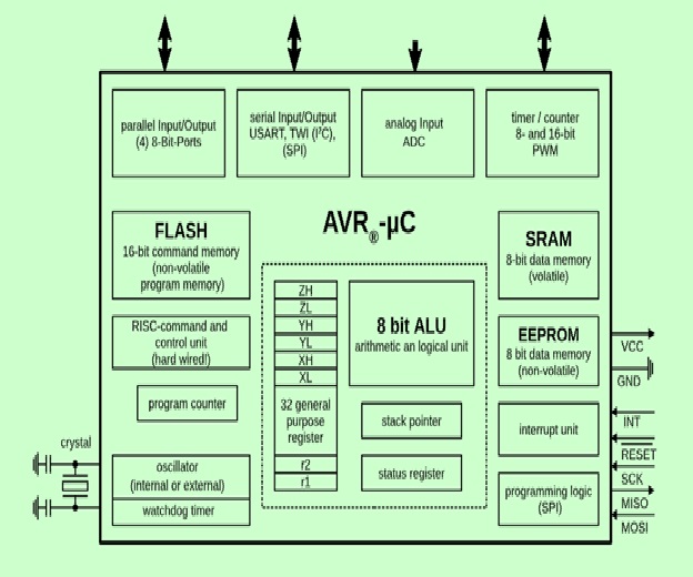
pin and architecture of microcontroller.
INTRODUCTION To PIC MICRO CONTROLLER
PIC is a Peripheral Interface Microcontroller which was developed in the year 1993 by the General Instruments
Microcontrollers. It is controlled by software and programmed in such a way that it performs different tasks and controls a generation line.
PIC microcontrollers are used in different new applications such as smartphones, audio accessories, and advanced medical devices.
There are many PICs available in the market ranging from PIC16F84 to PIC16C84. These types of PICs are affordable flash PICs.
Microchip has recently introduced flash chips with different types, such as 16F628, 16F877, and 18F452. The 16F877 costs twice the price
of the old 16F84, but it is eight times more than the code size, with more RAM and much more I/O pins, a UART, A/D converter and a lot more features.
The PIC microcontroller is based on RISC architecture. Its memory architecture follows the Harvard pattern of separate memories for program and data,
with separate buses.
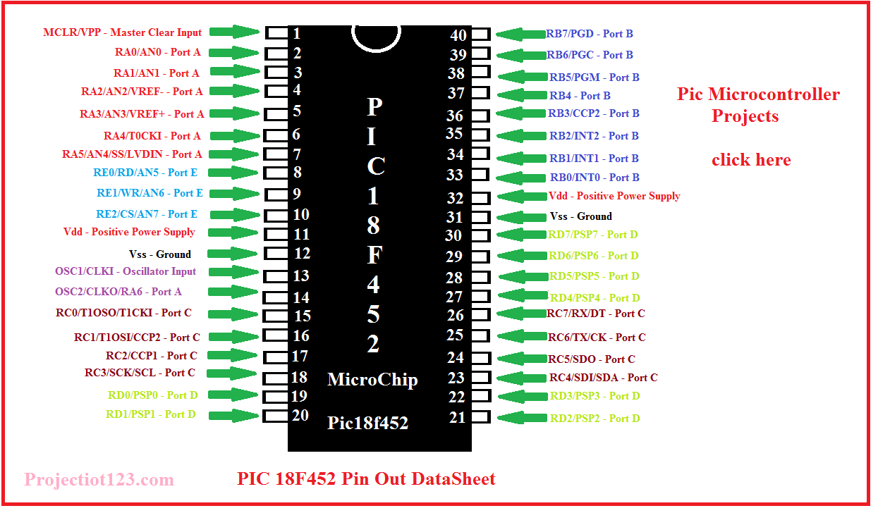
Pic Microcontroller
The PIC architecture consists of two memories: Program memory and Data memory. Program Memory: This is a 4K*14 memory space. It is used to store 13-bit instructions or the program code. The program memory data is accessed by the program counter register that holds the address of the program memory. The address 0000H is used as reset memory space and 0004H is used as interrupt memory space. Data Memory: The data memory consists of the 368 bytes of RAM and 256 bytes of EEPROM. The 368 bytes of RAM consists of multiple banks. Each bank consists of general-purpose registers and special function registers.
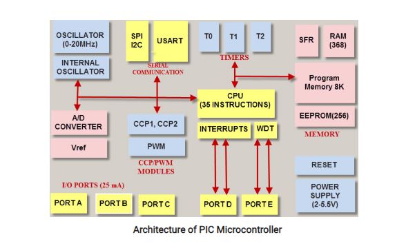
The architecture of Pic controller:
In short the comparison between Pic and Avr are as:
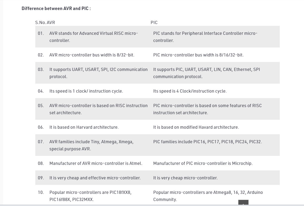
comparison between Pic and Avr.
Individual Assignments:
What is datasheet?
A datasheet, data-sheet, or spec sheet is a document that summarizes the performance and other characteristics of a product, machine, component (e.g., an electronic component), material,
subsystem (e.g., a power supply), or software in sufficient detail that allows a buyer to understand what the product is and a design engineer to understand the role of the component in the overall system.
Typically, a datasheet is created by the manufacturer and begins with an introductory page describing the rest of the document, followed by listings of specific characteristics,
with further information on the connectivity of the devices. In cases where there is relevant source code to include, it is usually attached near the end of the document or separated into another file.
Datasheets are created, stored, and distributed via product information management or product data management systems.
What does datasheet contain?
Manufacturer’s name
Product number and name
List of available package formats (with images) and ordering codes
Notable device properties
Short functional description
Pin connection diagram
Absolute minimum and maximum ratings :
supply voltage, power consumption, input currents, temperatures for storage, operating, soldering, etc
*Recommended operating conditions (as absolute minimum and maximum ratings)
DC specifications (various temperatures, supply voltages, input currents, etc.)
Maximum power consumption over the whole operating temperature range
AC specifications (various temperatures, supply voltages, frequencies, etc
Input/output wave shape diagram
Timing diagram
Reading Data Sheet
For the first task I was confused for choice as there is a numerous microcontrollers having similar capabilities and qualities after discussing with my instructor i select the attiny44 which i used
in week 7.
When dealing with electronics components, first thing to do is reading its datasheet. There are summary and complete datasheets.
For most important and common inforamtion, you can read the summary one.So i foud the following for the Attiny 44 from the data sheet.
Features
.High-performance.
.low-power Microchip AVR with 8-bit microcontroller
.High Endurance, Non-volatile Memory Segments
.4K Bytes of In-System
.Self-programmable Flash Program Memory
Pins Configuration
Beside having knowledge of features it also the most importantto know what pins you have in your microcontroller and so to know where you have to connect the components so they can work properly:
So the pins in attiny44 are :
> GND: ground.
> VCC: supply voltage.
> Port A (0-7): Port A is a 8-bit bi-directional I/O port with internal pull-up resistors.
> Port B (0-3): Port B is a 4-bit bi-directional I/O port with internal pull-up resistors.
> RESET: Reset input.
> MISO: Master Data input (the data comes into the microcontroller through this pin).
> MOSI: Master Data output (the data comes out to the microcontroller through this pin).
The below will help us to understand the pins configuration.
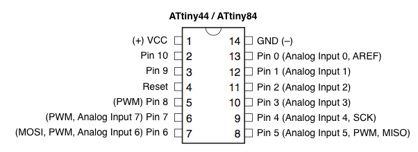
The pin configuration of attiny44.
the internal structure of the the attiny44 is given as:
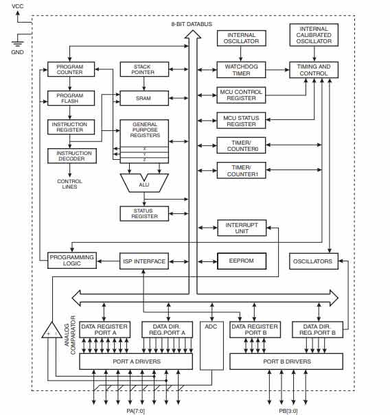
Internal structure of attiny44
Programming the board
In the the programming part of the assignment I used my hello world board as I designed in the electronic design.
Programming the board using Arduino IDE
Inorder to program your board using Arduino IDE,
first you have to perform following steps so that the IDE can detect your board:
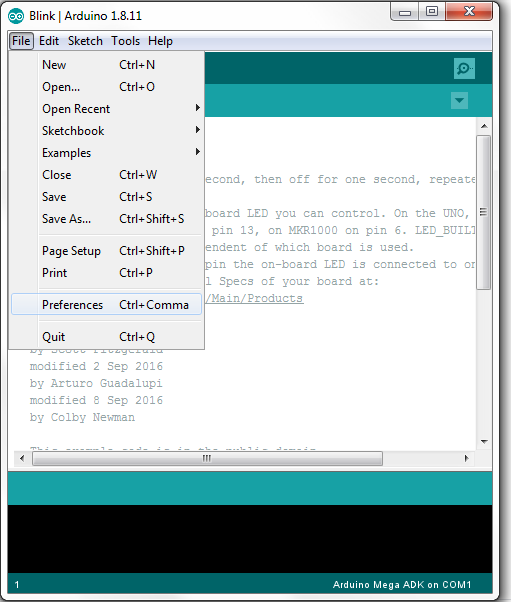
Open "Arduino IDE"
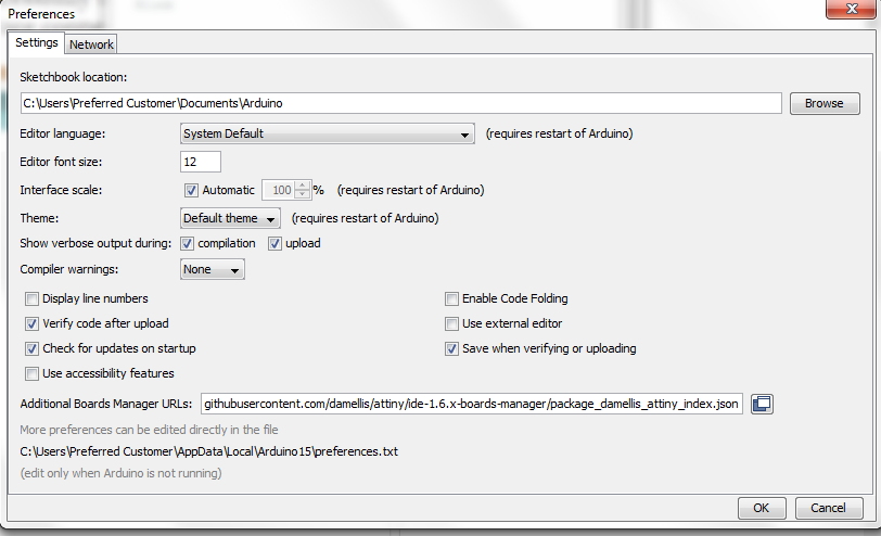
Go to "File", and the "Prefrences"
Clear the coloumn "Additional Boards Manager URLs"
Copy the link given over Here. Paste it and press "Ok"
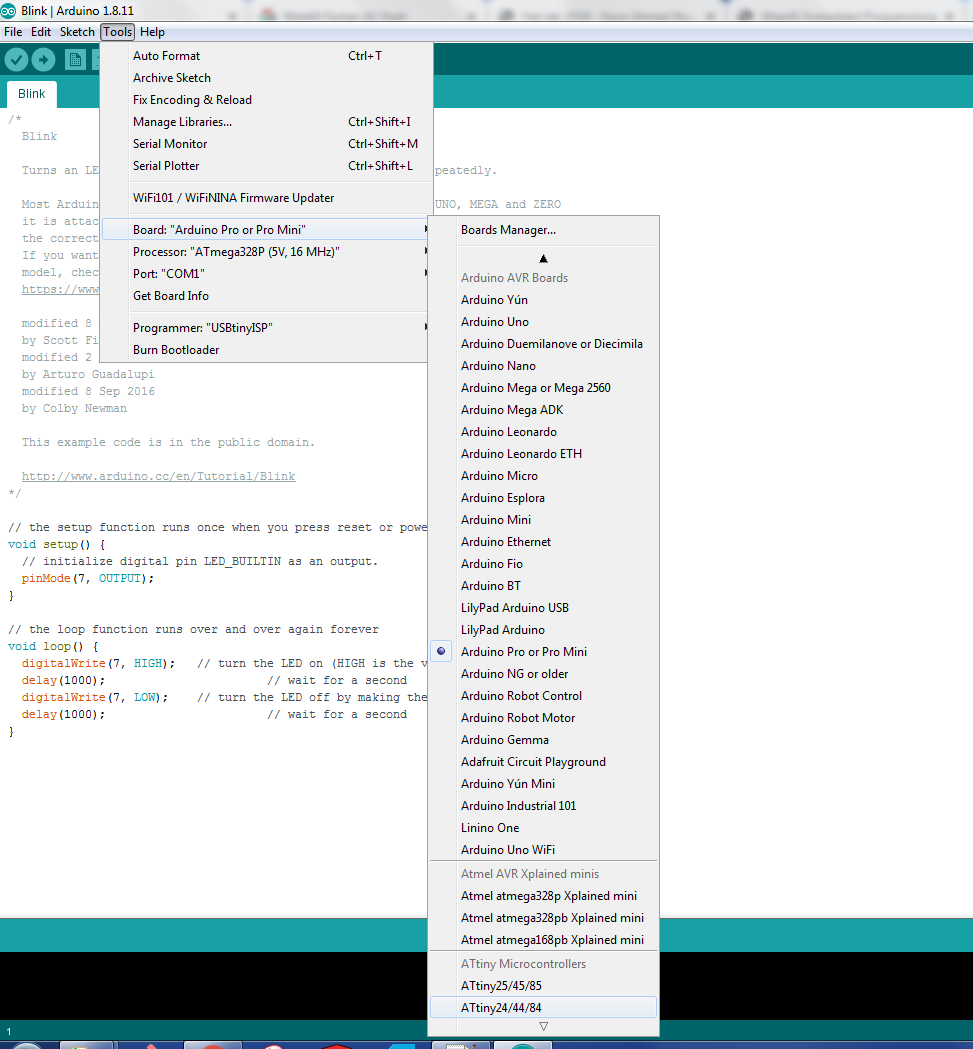
Then Go to "Tools", "Boards", "Boards Manager", and search for ATTiny, once you find that board then install it.
Again Go to "Tools", "Boards", "Boards Manager", and select ATtiny24/44/84
Then from "Processors" select your repective board i.e.ATtiny44
Now from "Clock", select the clock source of your chip i.e.External 20MHz
Go to "Programmer" and select USBTiny ISP, instead of "AVRISP mkll"
After setting all this, click on the Burn Bootloader option and see if it is successfully uploaded or not.
If "Yes" then proceed uploading other codes, if "No" then check your Hardware connections or repeat above steps until done.
programming
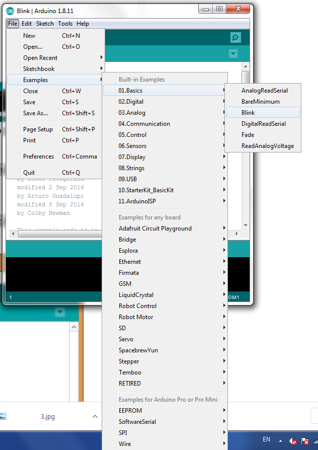
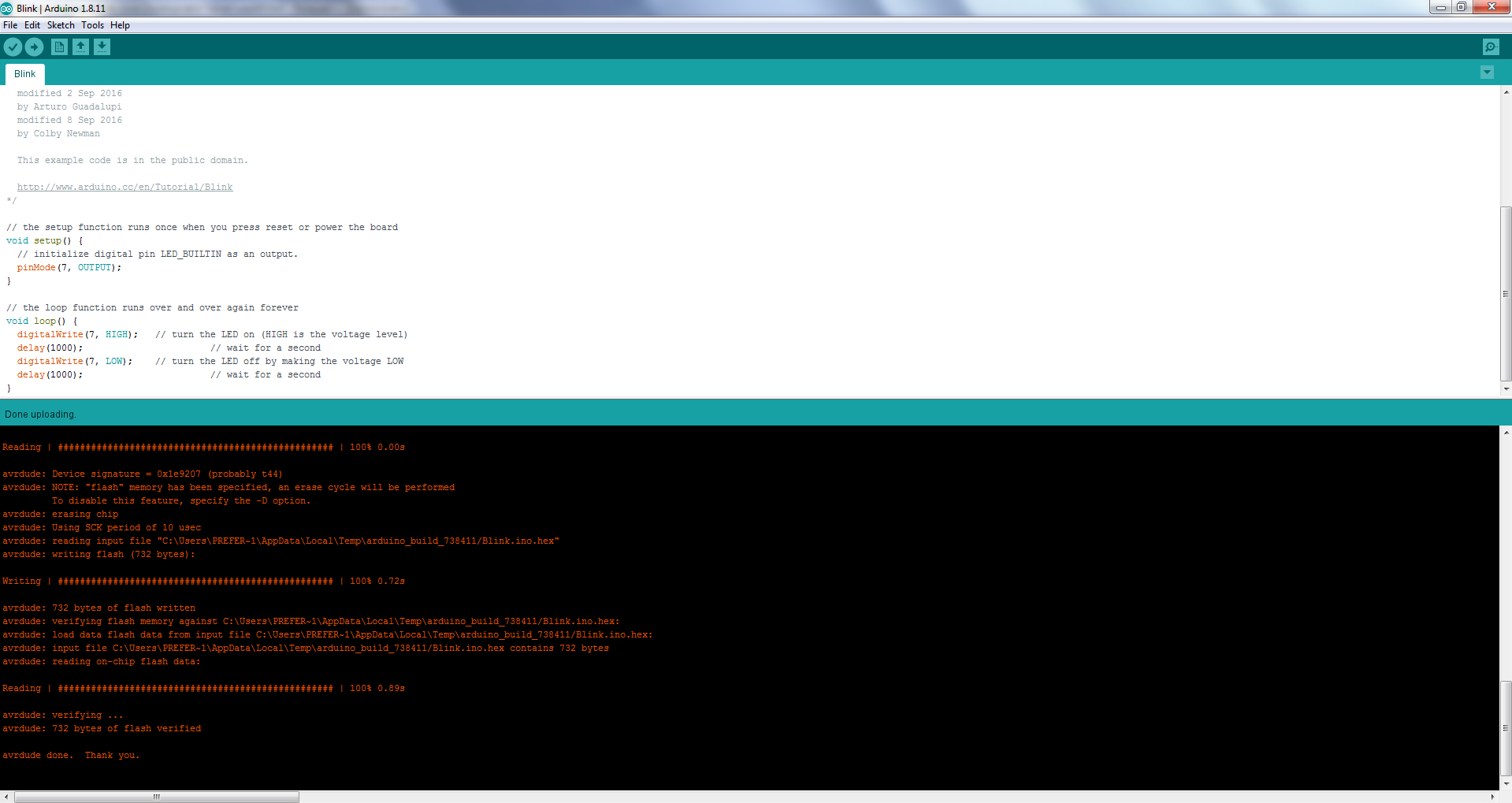
After configuration of my board, I uploaded the blink file from "Examples" available in Arduino IDE. Steps for that are mentioned,
shown below and the results as well:
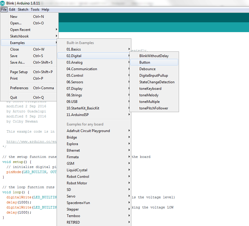
Go to "File", "Examples", "Basics", "Blink"
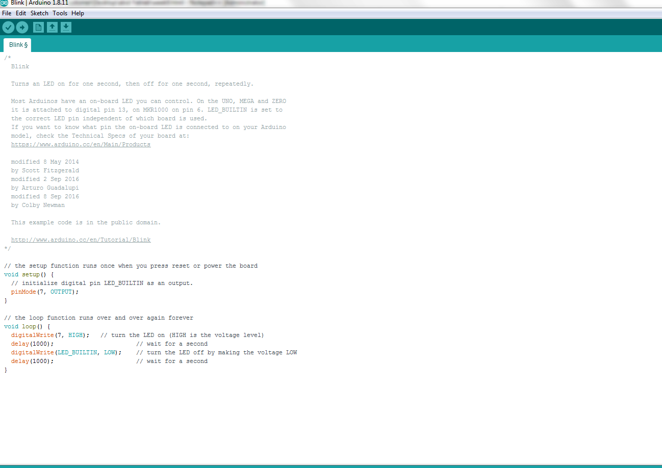
Replace the name of LED pin with the Pin number of your board, on which LED is connected.
Press the "Upload" button and see the results.
Video showing the blinking Led.
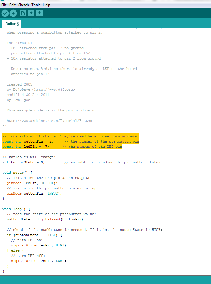
Inorder to make the Arduino Uno code for button and LED, compatible with ATTiny44 we need to
take care of their corresponding pins as well. First we need to see the Pins of ATTiny44 and which Arduino pins they are replicating in
the ATTiny circuit. This can be done by having a look at the image given above in pin configuration of attiny44.
This time we change the program and pin number for led and button and compile and upload. when we press the button the led will turn off and
in normally condition it will turn on as:
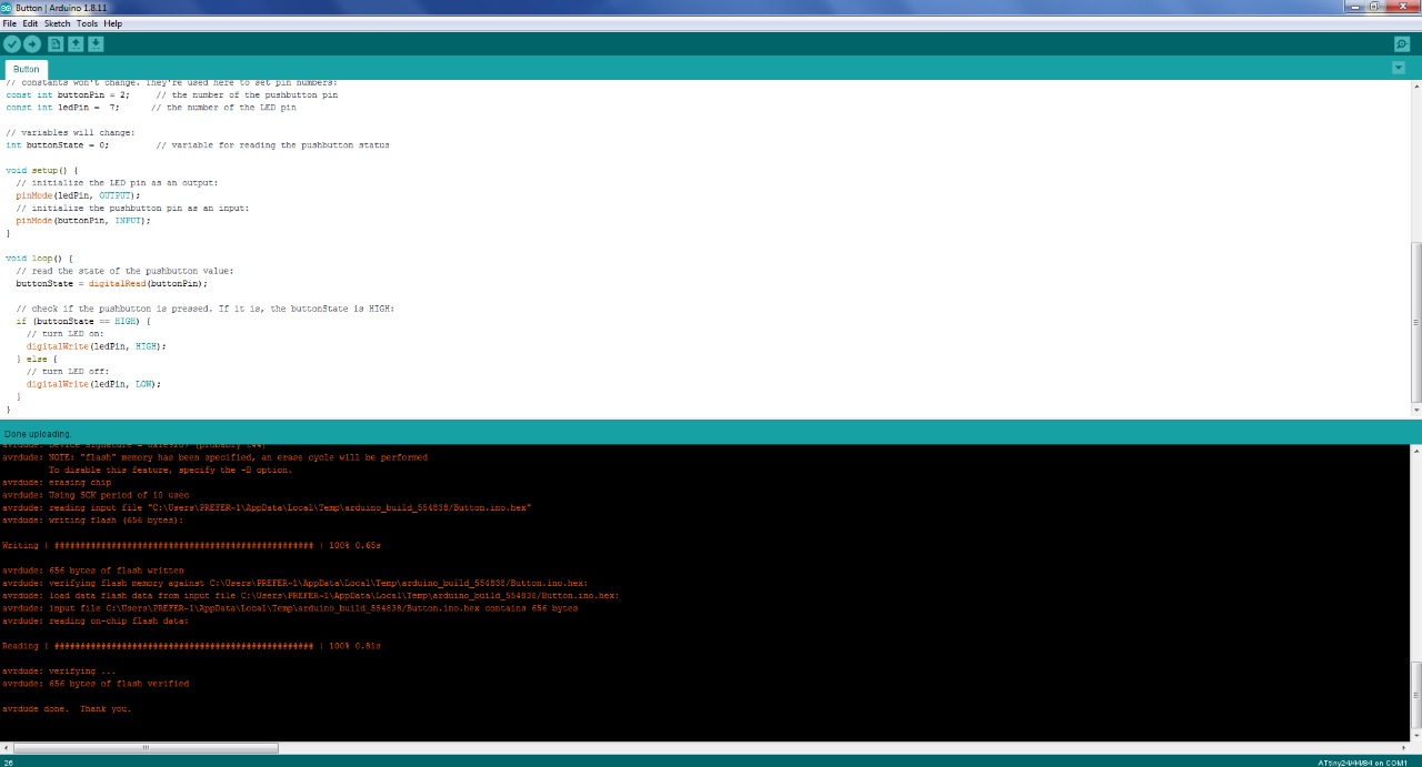
Video showing the button controlling the led.
A datasheet, data-sheet, or spec sheet is a document that summarizes the performance and other characteristics of a product, machine, component (e.g., an electronic component), material, subsystem (e.g., a power supply), or software in sufficient detail that allows a buyer to understand what the product is and a design engineer to understand the role of the component in the overall system. Typically, a datasheet is created by the manufacturer and begins with an introductory page describing the rest of the document, followed by listings of specific characteristics, with further information on the connectivity of the devices. In cases where there is relevant source code to include, it is usually attached near the end of the document or separated into another file. Datasheets are created, stored, and distributed via product information management or product data management systems.
Manufacturer’s name Product number and name List of available package formats (with images) and ordering codes Notable device properties Short functional description Pin connection diagram Absolute minimum and maximum ratings : supply voltage, power consumption, input currents, temperatures for storage, operating, soldering, etc *Recommended operating conditions (as absolute minimum and maximum ratings) DC specifications (various temperatures, supply voltages, input currents, etc.) Maximum power consumption over the whole operating temperature range AC specifications (various temperatures, supply voltages, frequencies, etc Input/output wave shape diagram Timing diagram
Reading Data Sheet
For the first task I was confused for choice as there is a numerous microcontrollers having similar capabilities and qualities after discussing with my instructor i select the attiny44 which i used
in week 7.
When dealing with electronics components, first thing to do is reading its datasheet. There are summary and complete datasheets. For most important and common inforamtion, you can read the summary one.So i foud the following for the Attiny 44 from the data sheet.
Features
.High-performance.
.low-power Microchip AVR with 8-bit microcontroller
.High Endurance, Non-volatile Memory Segments
.4K Bytes of In-System
.Self-programmable Flash Program Memory
Pins Configuration
Beside having knowledge of features it also the most importantto know what pins you have in your microcontroller and so to know where you have to connect the components so they can work properly:
So the pins in attiny44 are :
> GND: ground.
> VCC: supply voltage.
> Port A (0-7): Port A is a 8-bit bi-directional I/O port with internal pull-up resistors.
> Port B (0-3): Port B is a 4-bit bi-directional I/O port with internal pull-up resistors.
> RESET: Reset input.
> MISO: Master Data input (the data comes into the microcontroller through this pin).
> MOSI: Master Data output (the data comes out to the microcontroller through this pin).
The below will help us to understand the pins configuration.
The pin configuration of attiny44.
the internal structure of the the attiny44 is given as:
Internal structure of attiny44
Programming the board
In the the programming part of the assignment I used my hello world board as I designed in the electronic design.
Programming the board using Arduino IDE
Inorder to program your board using Arduino IDE,
first you have to perform following steps so that the IDE can detect your board:
Open "Arduino IDE"
Go to "File", and the "Prefrences"
Clear the coloumn "Additional Boards Manager URLs"
Copy the link given over Here. Paste it and press "Ok"
Then Go to "Tools", "Boards", "Boards Manager", and search for ATTiny, once you find that board then install it.
Again Go to "Tools", "Boards", "Boards Manager", and select ATtiny24/44/84
Then from "Processors" select your repective board i.e.ATtiny44
Now from "Clock", select the clock source of your chip i.e.External 20MHz
Go to "Programmer" and select USBTiny ISP, instead of "AVRISP mkll"
After setting all this, click on the Burn Bootloader option and see if it is successfully uploaded or not.
If "Yes" then proceed uploading other codes, if "No" then check your Hardware connections or repeat above steps until done.
programming
After configuration of my board, I uploaded the blink file from "Examples" available in Arduino IDE. Steps for that are mentioned,
shown below and the results as well:
Go to "File", "Examples", "Basics", "Blink"
Replace the name of LED pin with the Pin number of your board, on which LED is connected.
Press the "Upload" button and see the results.
Inorder to make the Arduino Uno code for button and LED, compatible with ATTiny44 we need to
take care of their corresponding pins as well. First we need to see the Pins of ATTiny44 and which Arduino pins they are replicating in
the ATTiny circuit. This can be done by having a look at the image given above in pin configuration of attiny44.
This time we change the program and pin number for led and button and compile and upload. when we press the button the led will turn off and
in normally condition it will turn on as: