This week was all aboutcomputer controlled Machining.In this week we learn about the CNC (Computer Numerical Control) that how the CNC work and what are thw benifits and advantages of CNC.We also learned about different parts and working Principals of the CNC and the softwares and Machine use in this week.
Assignments of the week
Individual Assignment
The individual assingment of this week is to Make Something Big (on a CNC machine).
For the individual assignment we had many idea and design in my mind .After discussing with my Instructor i decide to make a Baby Bed .I Started designinig
the baby bed in Solid Work.
for this first i make the base for the bed.
Making Base of the bed
After opening the solid work i start to draw the base and also define the parameter use in designinig of the bed.


fig:base of the bed after extrude boss, cut and setting parameters.
Making side rail of the bed
As I made the base now it is time to design the side for the bed in solid work. Before assign the size i import and export the parameters.


fig:side of the bed after extrude boss, cut and importing and exporting parameters.
Headboard slat of the bed
As for the bed we have to design the head board for bed.
So for that i designed the headboard in the solid works as a part.The given screen shot shows the design of the head board


fig:headboard slat for bed after sketching,extrude bass and cut.
Assemble
After makig (designing ) all the required parts now i assemble them.


fig:Assemble of different parts of Baby bed.
Make Drawing from Assembly.
Before moving toward the shopboot first we make the drawing from assemble and save in dxf file.


Opening and Setting in Vcurve software:
Before Going to sopboot ws have to give the tool path that according to which the machine will work . First I open the V curve software
and import the design to the software as:


Setting the position of parts according to the size of bed.


Description of toolpath
Once My Design is ready ,I use the [Toolpath] to set up my cuts.
Before selecting and adding tools path it is necessary to understand the following terms.
Select the paths that I will be using for the particular toolpath. there are many op[tion for selecting the tool path.
* 1. Cutting depth: Set it acording to the material thickness + 0.5-0.9mm so that it cuts through the bottom.
The different settings can be applied for up cut down cut combination.
* 2. Tool: Different tool are available in shopboot related and dedicated for specific job accordingly.
* 3. Machine Vector: I get choices of either Outside, Inside or On the vector.
This is important when you are cutting something specific to fit well and also with pockets.
* 4. Add Tabs to Toolpath:
To avoid the material pop out and move around messing everything up (and possibly hurting something) we need add Tabs to Toolpath: So I add The tabs
Bits Specifications
Bit material:
Router bits used in Shopbot are made from a variety of materials such as solid carbide, carbide-tipped steel, and high-speed steel.
Flute type:
There are four basic flute types: Straight, spiral up-cut, spiral down-cut, and compression.

Drill bit Vs End mills :
A drill bit need to cut straight into the material hence will have teeth at tip. But an End mill needs to cut from the sides also, that means it needs to have a cutting edge spiraling all the way up to the flute.

Upcut & Downcut:
In an Upcut type end mill the teeth on the flute will point upwards. This means that the end mill is cutting and drawing out the wood through the flute.
This is good for cutting deep into the stock. But this leaves a bad surface finish on the top of the surface.
A downcut type end mill has teeths that point downward on the flute. This means that the end mill will cut and try to push the material into the stock.
This will give good surface finish on the top, but it is not very efficient at removing material.

Flat/ball end:
Flat end leaves flat surface profile on the stock and are good for removing large volume of material, but steps are formed when used for making curved surfaces.
Ball end leaves curved surfaces and forms smooth curved finish while cutting cavities. They are used for finishing cuts.

Collet and Covernut
A collet is a subtype of chuck that forms a collar around an object to be held and exerts a strong clamping force on the object when it is tightened.
It may be used to hold a workpiece or a tool. We are using ER25 collets, ER collets are slotted (alternately) from both ends and therefore compress onto the cutter along the whole length of the collet when tightened.
This not only provides a better grip on the cutter shank but also allows some variation (typically 1mm) in shank sizes that may be used in a single collet.
The smaller size collets are best used to hold cutters no more than 0.5mm below the nominal size. Collets are inserted into the covernut.


Setting the Toolpath

Giving the file to the machine
Once the toolpath set give the file to the shopbot machine for cutting.
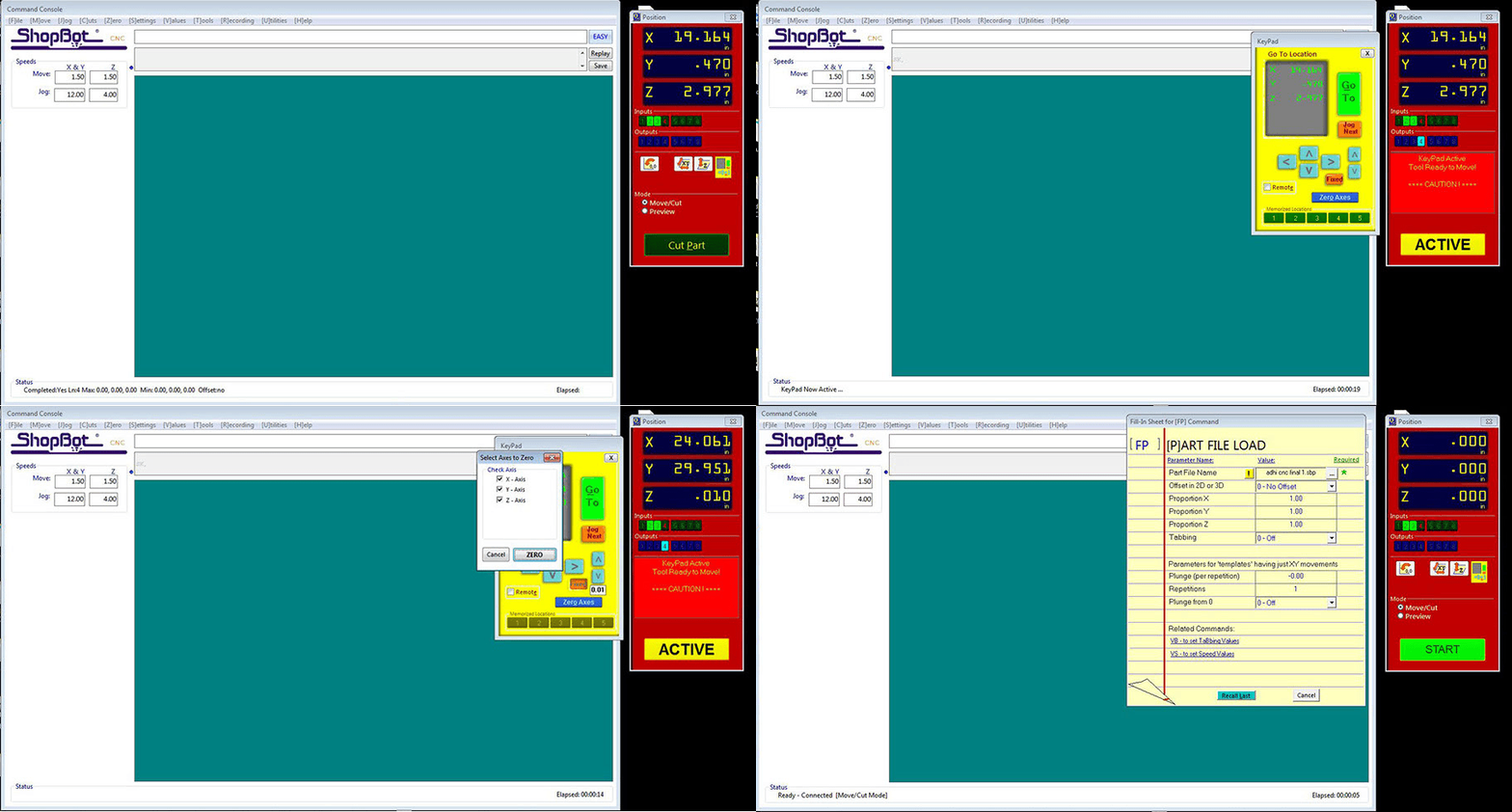
First we set the axis and then give the file for cutting:

After cutting and assembling


Final result.
Group Assignment:
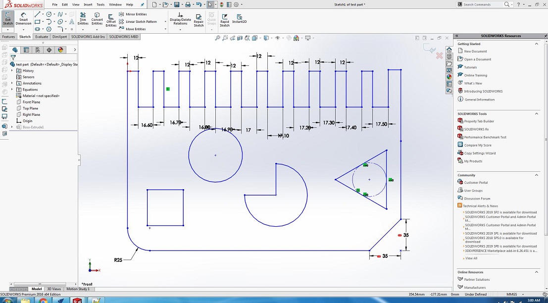
The group assignment of this week is we have to test run out, alignment, speeds, feeds, and toolpaths for your machine.
For this we made a design in solid works and cut it in CNC.


After Cutting


We have the MDF sheets in lab with thickness of 16.3mm. So we cutted part in that sheet, we used both outside cut and inside cut on different areas
and also used pocket tool path you can also see in image and after cutting it was fixing in 16.7mm cutted area,
we cutted this area with outside cut toolpath.
Download all files from here
Individual Assignment
The individual assingment of this week is to Make Something Big (on a CNC machine).
For the individual assignment we had many idea and design in my mind .After discussing with my Instructor i decide to make a Baby Bed .I Started designinig
the baby bed in Solid Work.
for this first i make the base for the bed.
Making Base of the bed
After opening the solid work i start to draw the base and also define the parameter use in designinig of the bed.


fig:base of the bed after extrude boss, cut and setting parameters.
Making side rail of the bed
As I made the base now it is time to design the side for the bed in solid work. Before assign the size i import and export the parameters.


fig:side of the bed after extrude boss, cut and importing and exporting parameters.
Headboard slat of the bed
As for the bed we have to design the head board for bed. So for that i designed the headboard in the solid works as a part.The given screen shot shows the design of the head board


fig:headboard slat for bed after sketching,extrude bass and cut.
Assemble
After makig (designing ) all the required parts now i assemble them.


fig:Assemble of different parts of Baby bed.
Make Drawing from Assembly.
Before moving toward the shopboot first we make the drawing from assemble and save in dxf file.


Opening and Setting in Vcurve software:
Before Going to sopboot ws have to give the tool path that according to which the machine will work . First I open the V curve software and import the design to the software as:


Setting the position of parts according to the size of bed.


Description of toolpath
Once My Design is ready ,I use the [Toolpath] to set up my cuts.
Before selecting and adding tools path it is necessary to understand the following terms.
Select the paths that I will be using for the particular toolpath. there are many op[tion for selecting the tool path.
* 1. Cutting depth: Set it acording to the material thickness + 0.5-0.9mm so that it cuts through the bottom.
The different settings can be applied for up cut down cut combination.
* 2. Tool: Different tool are available in shopboot related and dedicated for specific job accordingly.
* 3. Machine Vector: I get choices of either Outside, Inside or On the vector.
This is important when you are cutting something specific to fit well and also with pockets.
* 4. Add Tabs to Toolpath:
To avoid the material pop out and move around messing everything up (and possibly hurting something) we need add Tabs to Toolpath: So I add The tabs
Bits Specifications
Bit material:
Router bits used in Shopbot are made from a variety of materials such as solid carbide, carbide-tipped steel, and high-speed steel.
Flute type:
There are four basic flute types: Straight, spiral up-cut, spiral down-cut, and compression.

Drill bit Vs End mills :
A drill bit need to cut straight into the material hence will have teeth at tip. But an End mill needs to cut from the sides also, that means it needs to have a cutting edge spiraling all the way up to the flute.

Upcut & Downcut:
In an Upcut type end mill the teeth on the flute will point upwards. This means that the end mill is cutting and drawing out the wood through the flute.
This is good for cutting deep into the stock. But this leaves a bad surface finish on the top of the surface.
A downcut type end mill has teeths that point downward on the flute. This means that the end mill will cut and try to push the material into the stock.
This will give good surface finish on the top, but it is not very efficient at removing material.

Flat/ball end:
Flat end leaves flat surface profile on the stock and are good for removing large volume of material, but steps are formed when used for making curved surfaces.
Ball end leaves curved surfaces and forms smooth curved finish while cutting cavities. They are used for finishing cuts.

Collet and Covernut
A collet is a subtype of chuck that forms a collar around an object to be held and exerts a strong clamping force on the object when it is tightened.
It may be used to hold a workpiece or a tool. We are using ER25 collets, ER collets are slotted (alternately) from both ends and therefore compress onto the cutter along the whole length of the collet when tightened.
This not only provides a better grip on the cutter shank but also allows some variation (typically 1mm) in shank sizes that may be used in a single collet.
The smaller size collets are best used to hold cutters no more than 0.5mm below the nominal size. Collets are inserted into the covernut.


Setting the Toolpath

Giving the file to the machine
Once the toolpath set give the file to the shopbot machine for cutting.
First we set the axis and then give the file for cutting:

After cutting and assembling


Final result.
Group Assignment:
The group assignment of this week is we have to test run out, alignment, speeds, feeds, and toolpaths for your machine.
For this we made a design in solid works and cut it in CNC.


After Cutting


We have the MDF sheets in lab with thickness of 16.3mm. So we cutted part in that sheet, we used both outside cut and inside cut on different areas and also used pocket tool path you can also see in image and after cutting it was fixing in 16.7mm cutted area, we cutted this area with outside cut toolpath.