Group Assignment
* Send a message between two projects
Serial Communication Between Two Controller
Serial communication on pins TX or RX uses TTL logic levels (5V or 3.3V depending on the board).
Don't connect these pins directly to an RS232 serial port; they operate at +/- 12V and can damage your Arduino board. Serial is used for communication between
the Arduino board and a computer or other devices. All Arduino boards have at least one serial port (also known as a UART or USART): Serial.
It communicates on digital pins 0 (RX) and 1 (TX) as well as with the computer via USB.
The two Arduino boards are connected serially.
The TX of the Transmitter Arduino is connected with the RX of the Receiver Arduino.
The RX of the Transmitter Arduino is connected with the TX of the Receiver Arduino. in the simulation it doesn't matter if you don't
connect the grounds of both the Arduino's, but in reality make sure you connect the grounds of both the Arduino's.
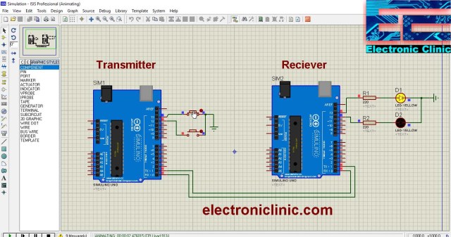
This is connection diagram using proteus simulation.
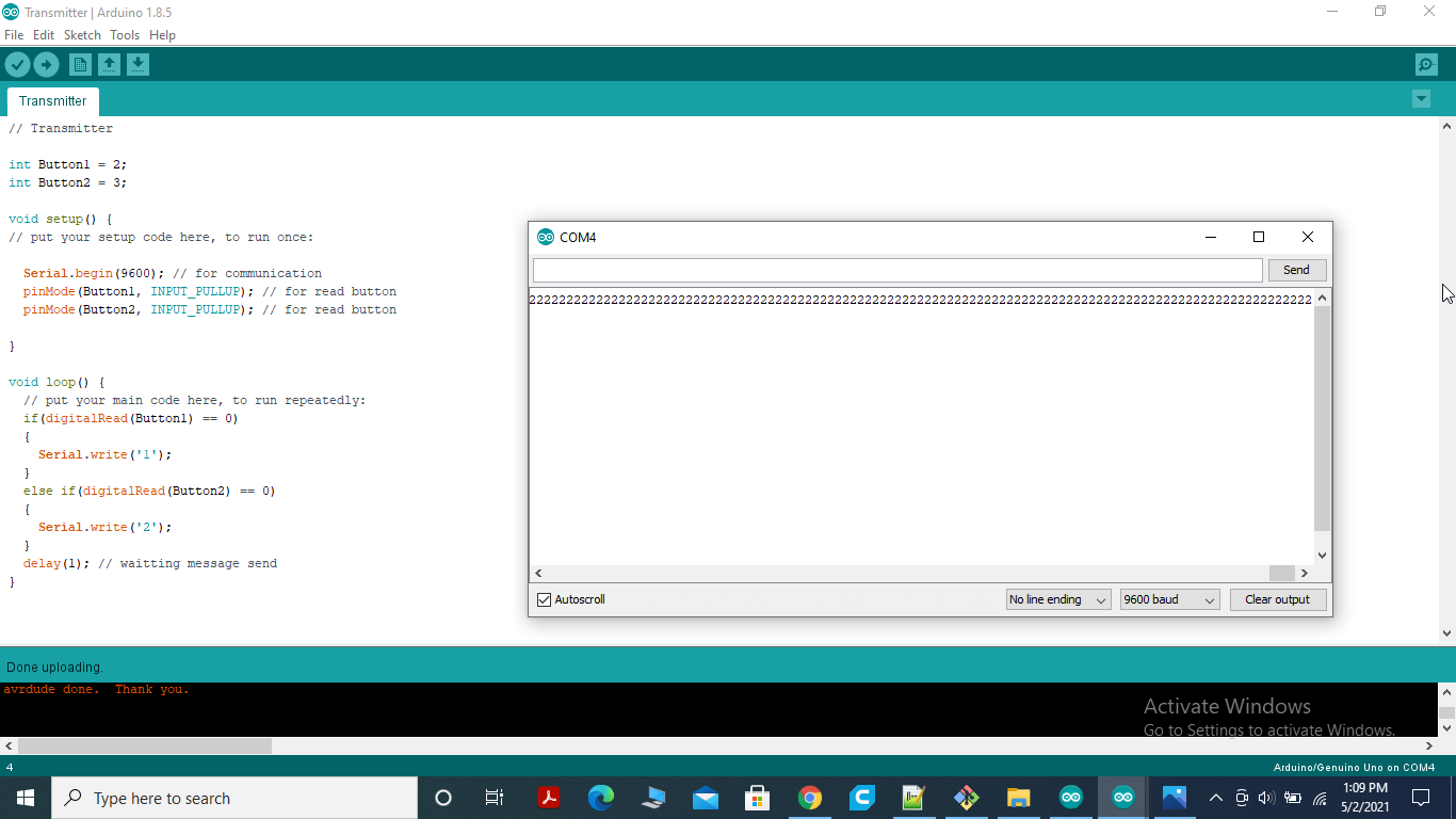
TRANSMITTER CODE
This is connection diagram using proteus simulation.
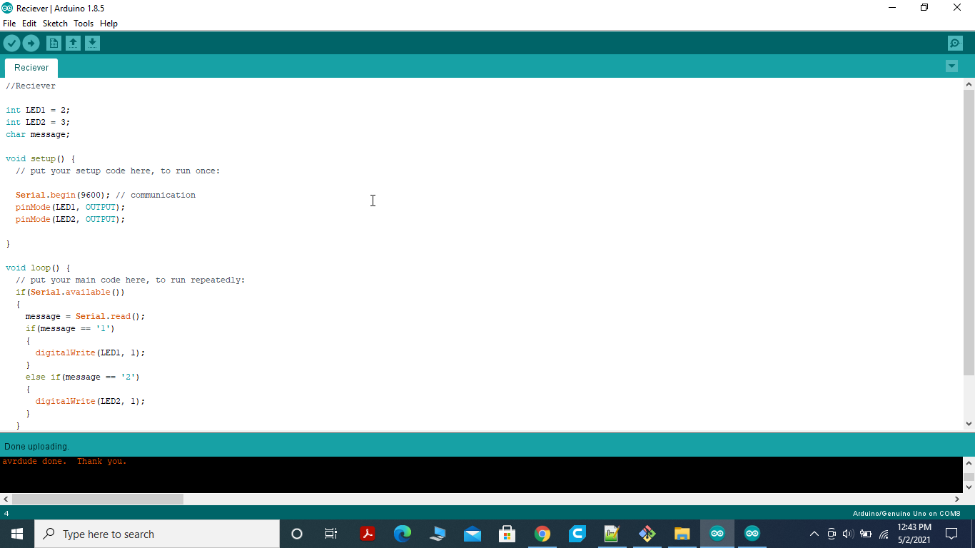
Receiver Code
This is connection diagram using proteus simulation.
Individual Assignment
Design, Build, and connect wired or wireless node(s) with network or bus addresses.
This week we learned about the ways circuits can talk(communicate) to each other. Before moving toward my week assignment I first study about different
communication channel.
Types of Communications:
1.Serial Communication:
In telecommunication and data transmission, serial communication is the process of sending data one bit at a time, sequentially,
over a communication channel or computer bus. This is in contrast to parallel communication, where several bits are sent as a whole,
on a link with several parallel channels.
Reference is
Here.
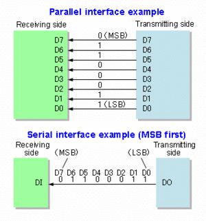
difference between serial and parallel communication.
2.UART(Universal Asynchronous Receiver/Transmitter)
In UART communication, two UARTs communicate directly with each other. The transmitting UART converts parallel data from a controlling
device like a CPU into serial form, transmits it in serial to the receiving UART, which then converts the serial data back into parallel data
for the receiving device. Only two wires are needed to transmit data between two UARTs. Data flows from the Tx pin of the transmitting UART to
the Rx pin of the receiving UART:
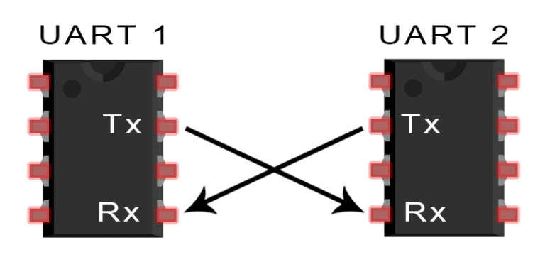
Pin configuration in UART communication.
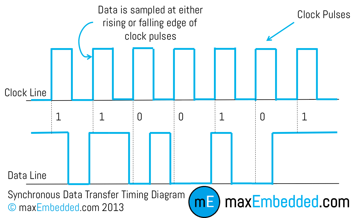
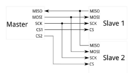
3. SPI:
The Serial Peripheral Interface SPI bus is a synchronous master-salve serial communication interface used for short distance communication,
primarily in embedded systems. With an SPI connection there is always one master device (usually a microcontroller) which controls the peripheral
devices. We should always share the ground Pins between the MCUs. Typically there are three lines common to all the devices:
* MISO (Master In Slave Out) - The Slave line for sending data to the master,
* MOSI (Master Out Slave In) - The Master line for sending data to the peripherals,
* SCK (Serial Clock) - The clock pulses which synchronize data transmission generated by the master and one line specific for every device:
* SS (Slave Select) - the pin on each device that the master can use to enable and disable specific devices.
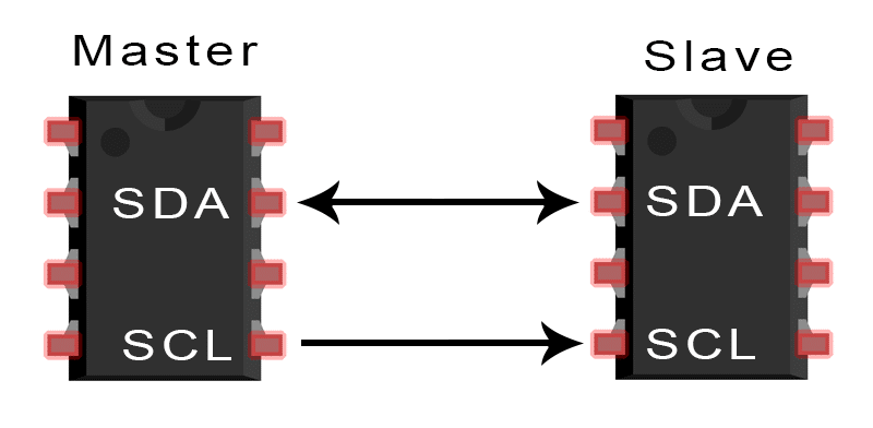
Connection in I2C
4.I2C
I2C combines the best features of SPI and UARTs. With I2C, you can connect multiple slaves to a single master (like SPI) and you can
have multiple masters controlling single, or multiple slaves. This is really useful when you want to have more than one microcontroller
logging data to a single memory card or displaying text to a single LCD. Like UART communication, I2C only uses two wires to transmit
data between devices:
After Studying about different connection I decide to communicate between the Arduino I made with other Arduino Through I2C Communication.
For this I used the arduinoI design in Input Devices week.
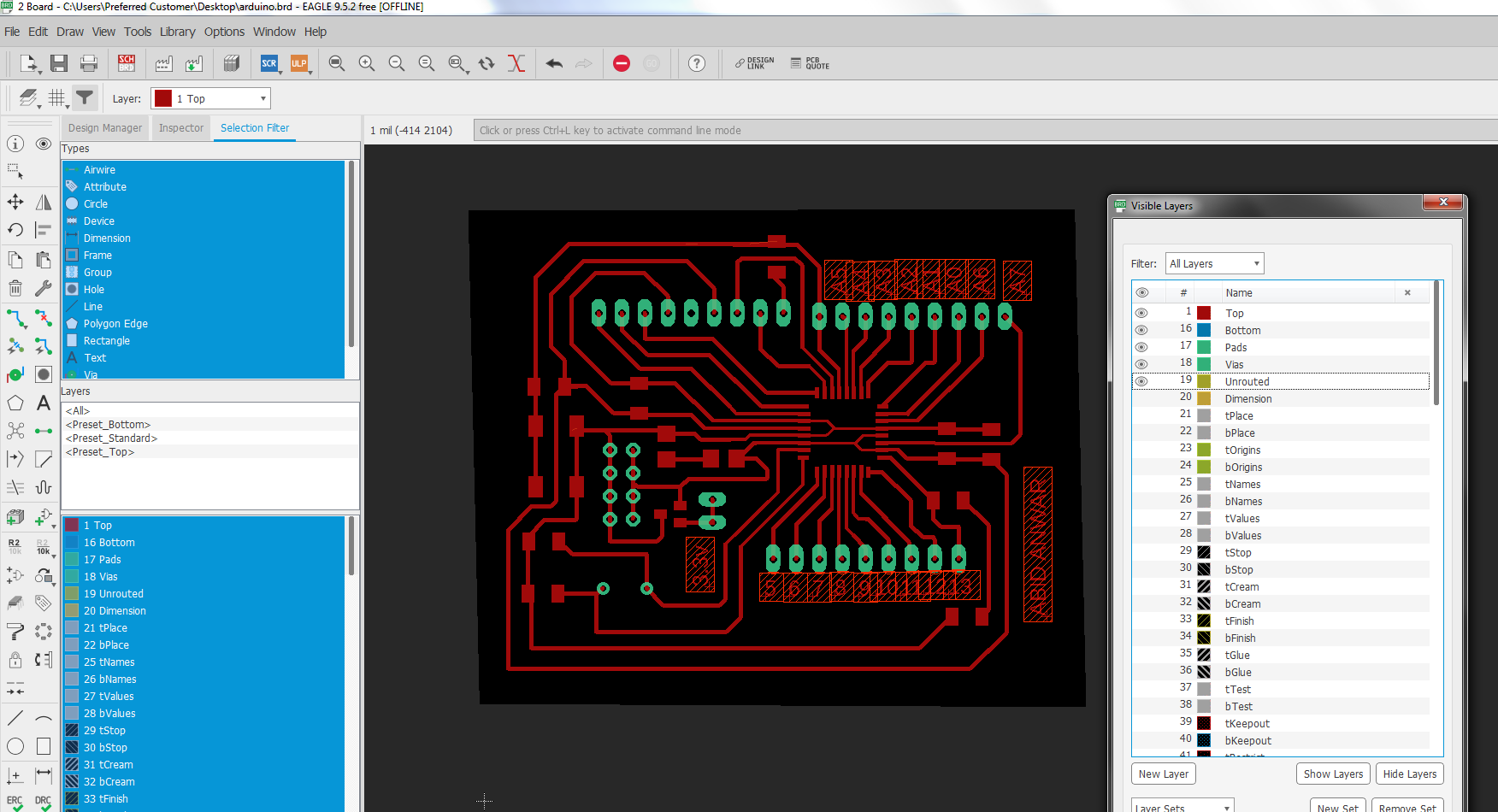
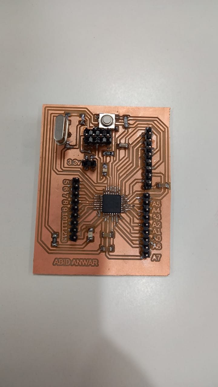
Circuit used in the communication.
You can find more about the board Here.
In this assignment I used the Builden arduino as a master and the arduino I design used as a slave and connect two component LED and the Motor. I
used the Potentiometer to change the value. The main activity is to connect the master board with the slave board which is assure by adding the
potentimeter
at the master board and the Led and the motor at the Slave board as when change the value of potentiometer
at the master board the slave board will follow it and perform task accordingly. I refer the following picture for connection:
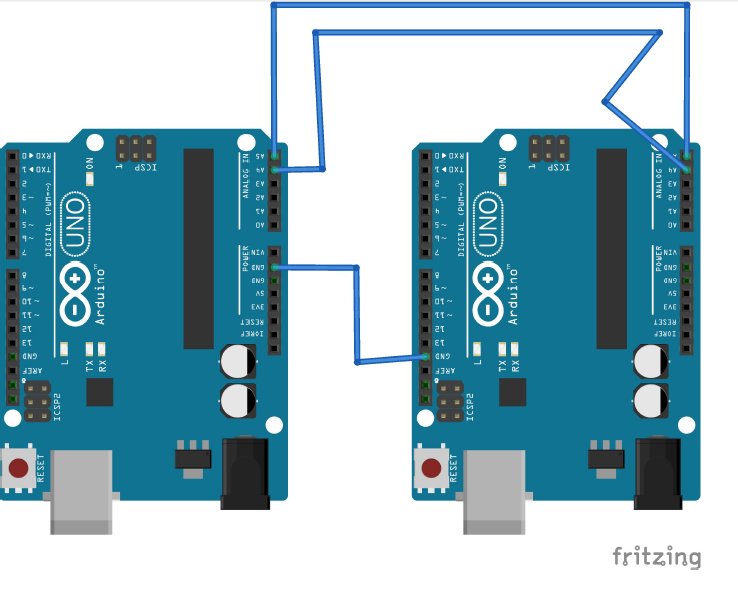
Circuit used as a reference .
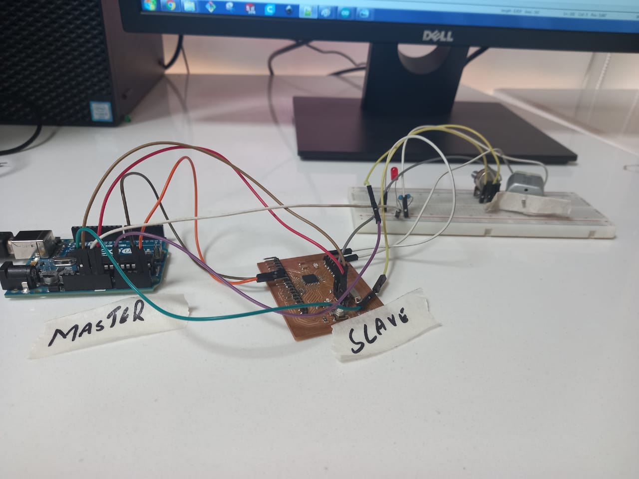
After connection.
Programming
After doing the connection it is time for the programming. First I program the Master board as:
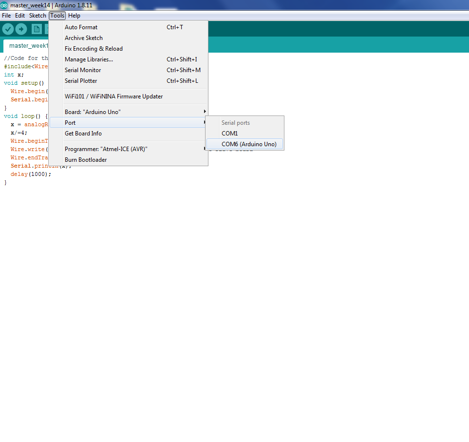
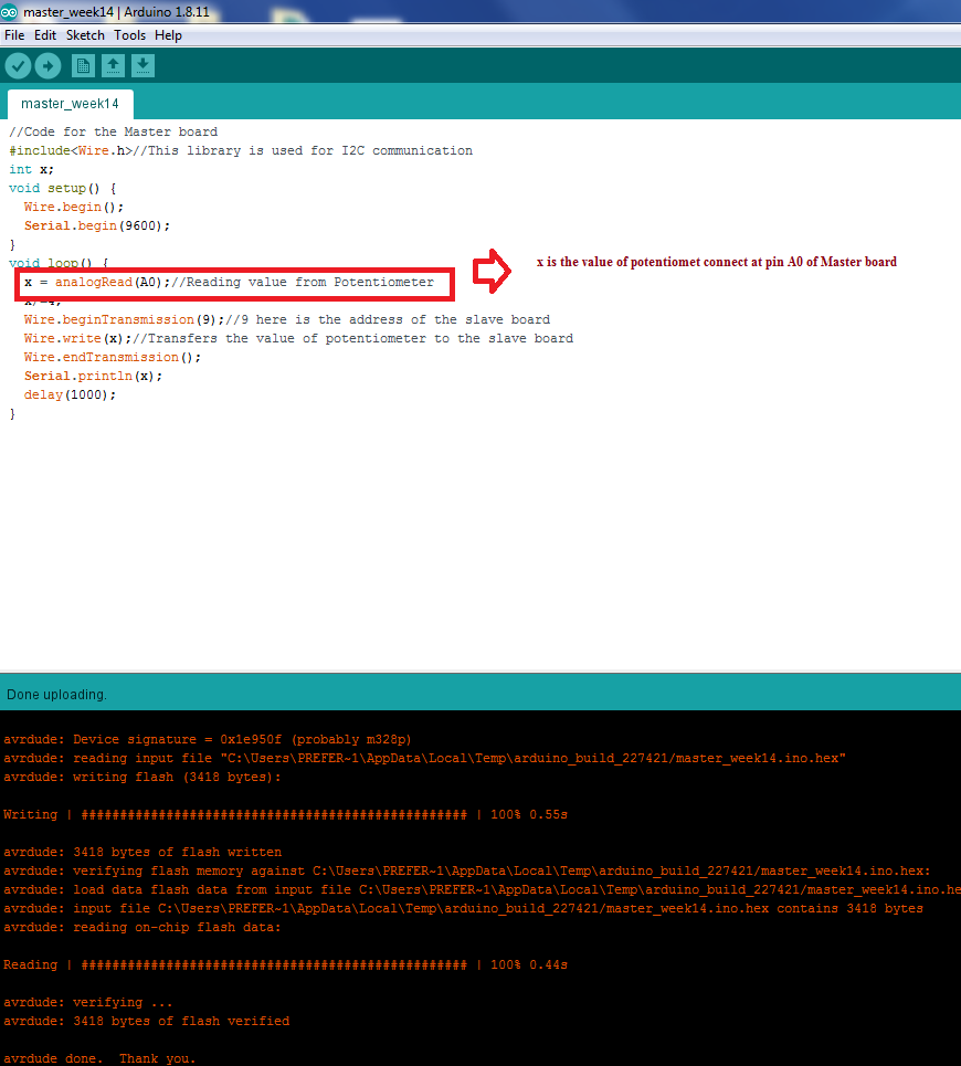
coding in master board.
Now I Program for the slave board as in such a way that the Pin10 and Pin13 are output and when the value of x reach at certain value the Pins values will On.
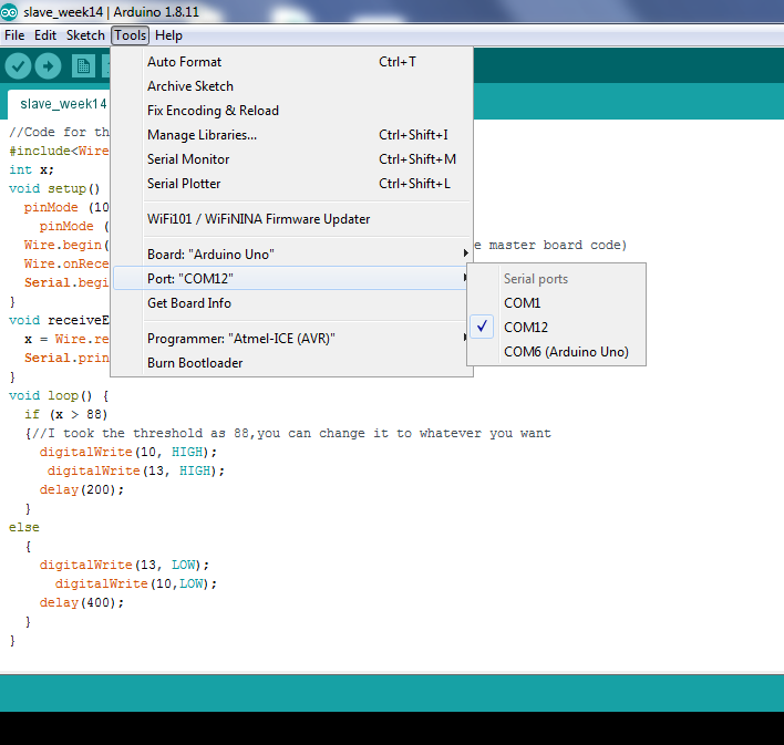
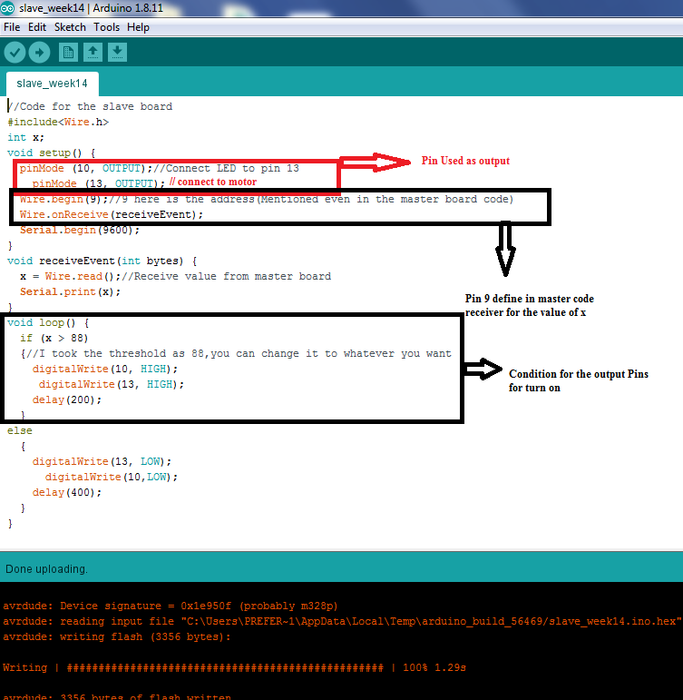
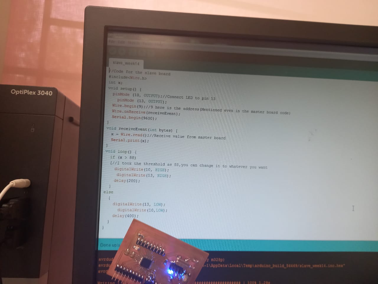
coding in Slave board.
After execution of the code the boards communicate perfectly as when the value of x is less then 88 the LED and the Motor are off as :
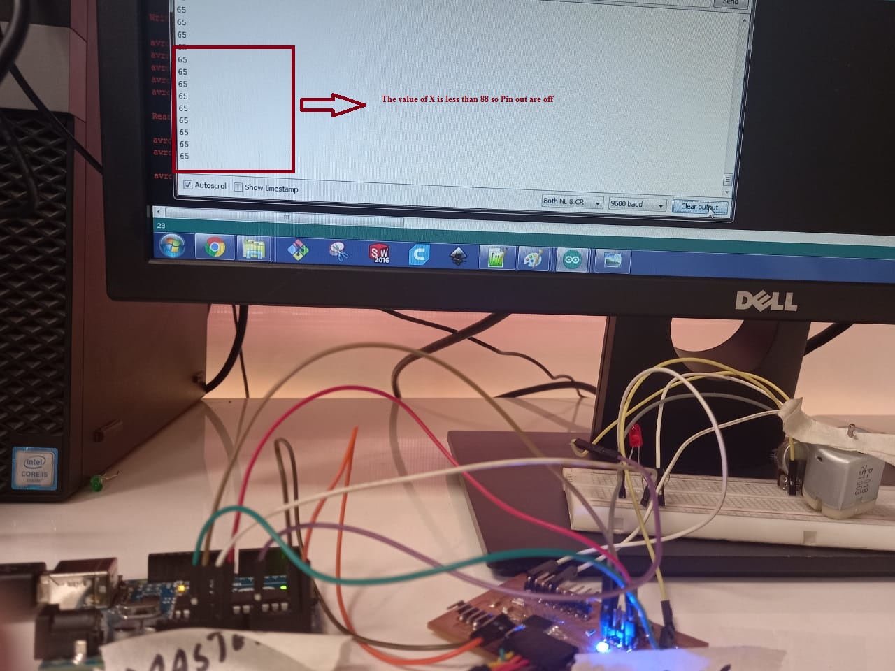
As value of x is less then predefined value the pins are off.
Now I change the value of the potentiometer which is the value of x and greater then 88 so the Pins are on.
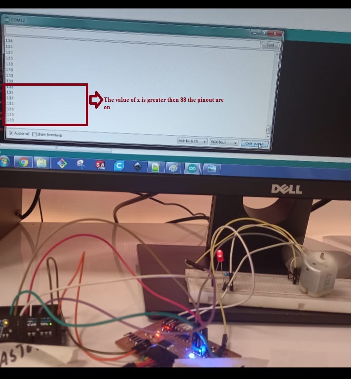
As value of x is greater then predefined value the pins are off.
The video showing the Communication between the boards: