5. Electronics production
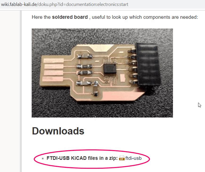
FTDI-USB board + UPDI board + HalloD1614
The FTDI-USB board fulfills the task of an FTDI-cable here. The card can convert from USB to serial and can be used to communicate with a microcontroller. It is also compatible with UPDI programming.
For this reason, the microcontroller can, in connection with the UPDI board, program the HelloD1614 board (inspired by the Adrinanino) via the UPDI interface, as this also has a UPDI connection.
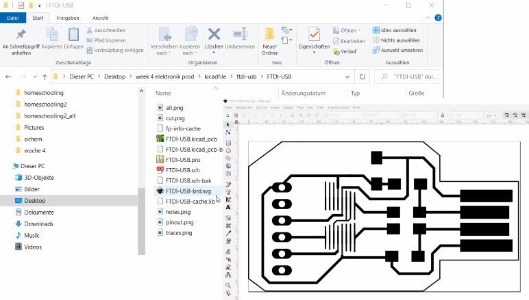
To recreate the programmer, I first download the kicad file from our wiki. Then I unzip the file and open it in kicad.
Kicad .svg to .png with Inkscape
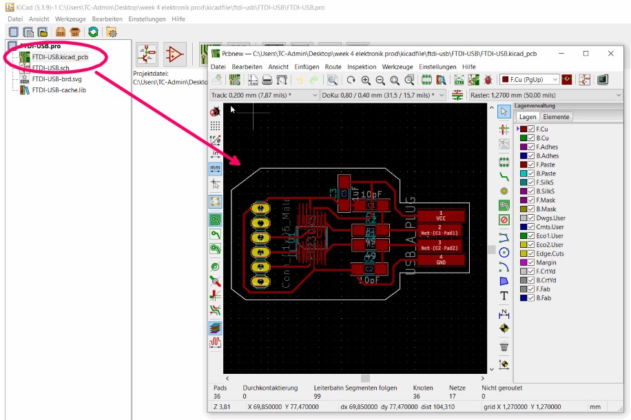
When I double click on FTDI-USB.kicad_pcb the drawing is displayed.
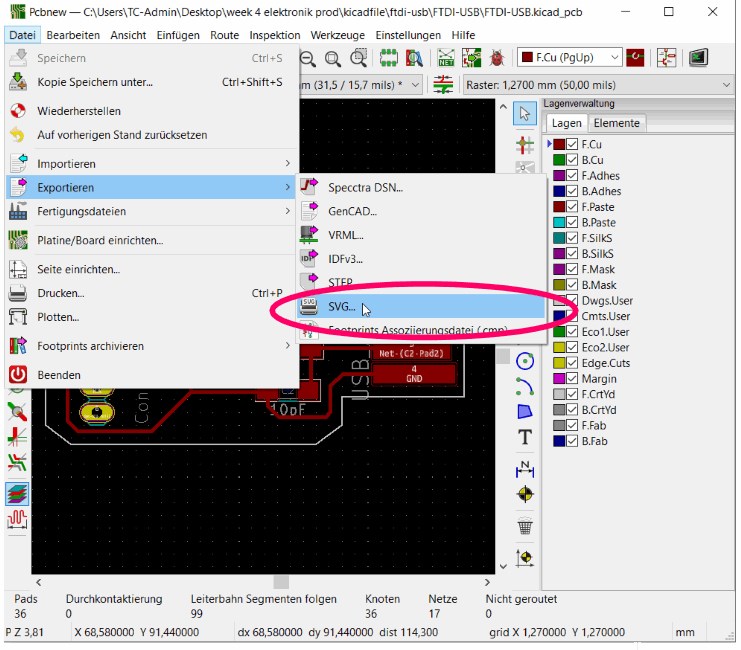
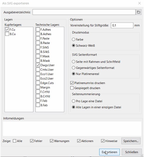
I export it with the following settings and create a .SVG
I import the .SVG file into Inkscape,
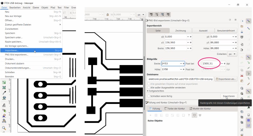
to export it as .png with the following settings.
create the .png for Fabmodule/Gcodes with Gimp
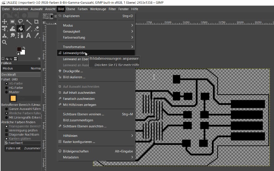
Now I open the .png image file in Gimp
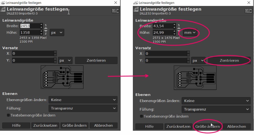
and enlarge the canvas by 2mm.
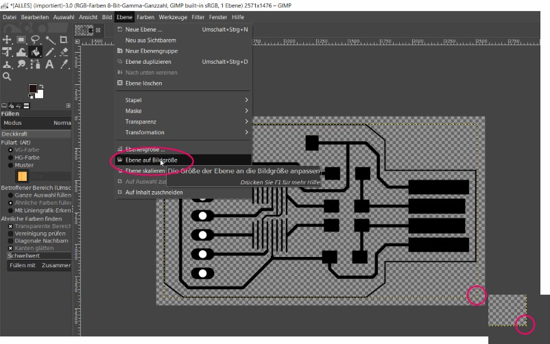
After adjusting the level to the picture size (necessary for the cutout),
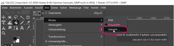
do I convert the indexed image to colors.
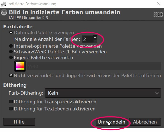
I limit the number of colors to 2.
So I only get black and white.
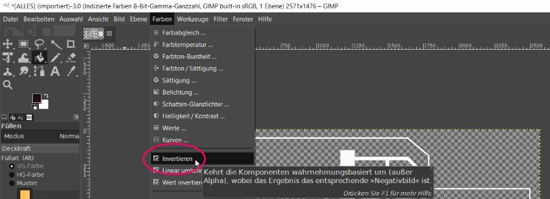
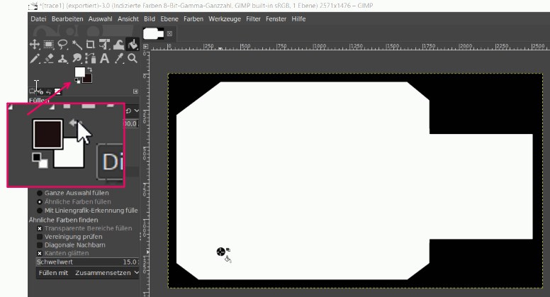
Now I invert the lines
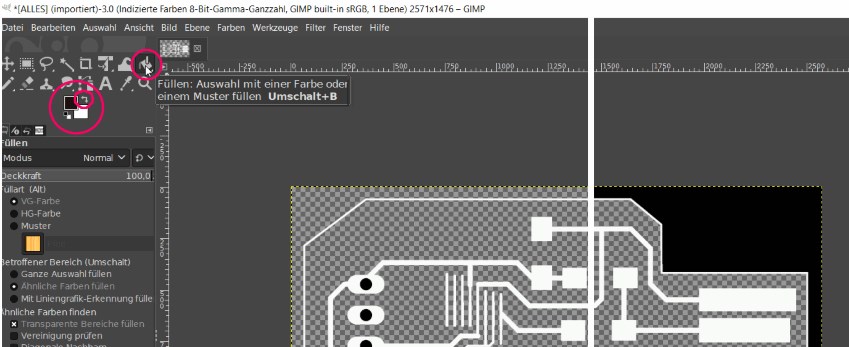
and fill everything with black, whats not needed in the moment.
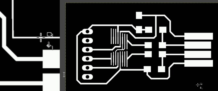
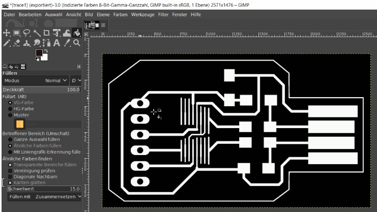
This way I get the picture with which I can create the g-code for the conductor tracks on the PCB.
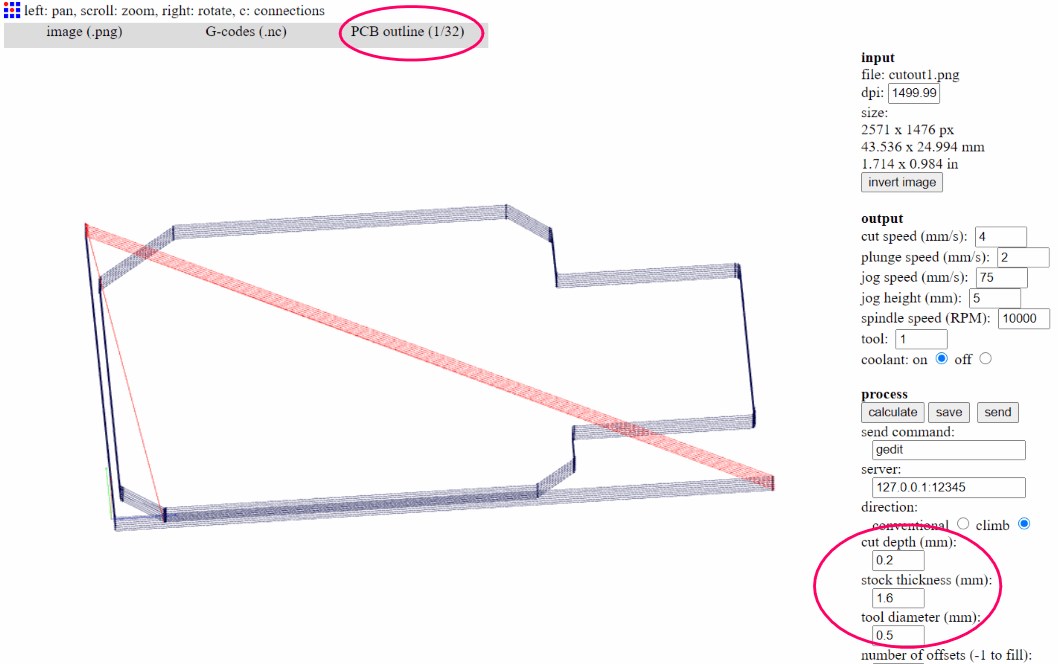
To get the cutout, I press ctrl Z and undo the last action on the picture. The white border becomes visible again.
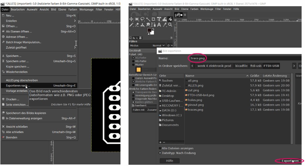
To get the picture for the cutout I fill inside the frame with white.
Then I export it as cutout.
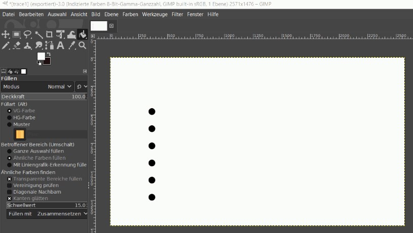
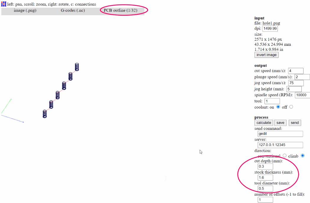
In order to be able to create the g-code for the holes, I restore them (ctrl Z) and export the .png again under the name holes.
create the gcodes with fabmodules
- http://fabmodules.org/ The next step is to upload the pictures to fabmodules,
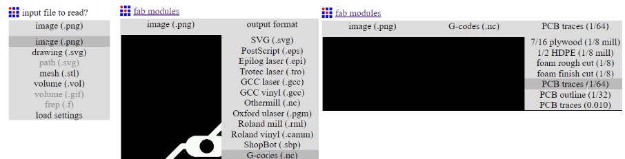
adapt everything to my machine setting and download the g-code. To do this, I am guided through the menu above, where I have different options depending on my machine setting and also have to decide on the type of job.
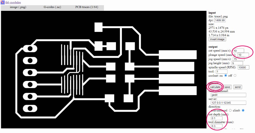
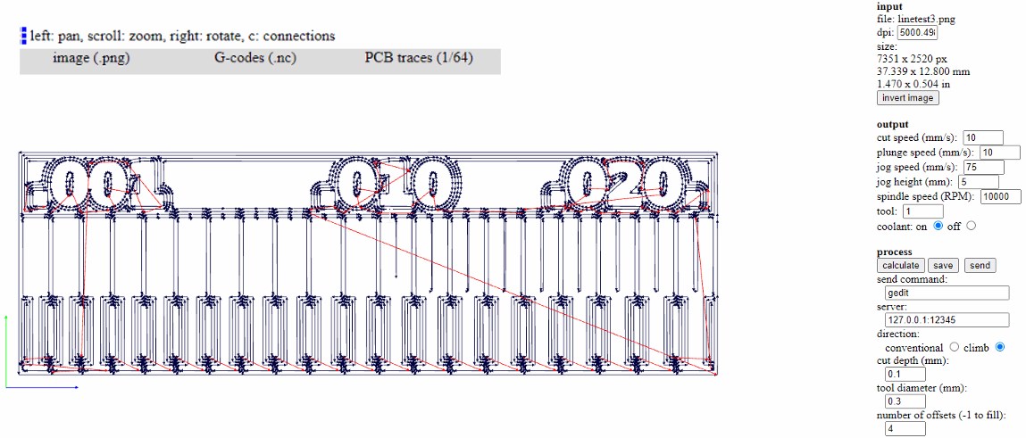
I start with the PCB traces 1/64.
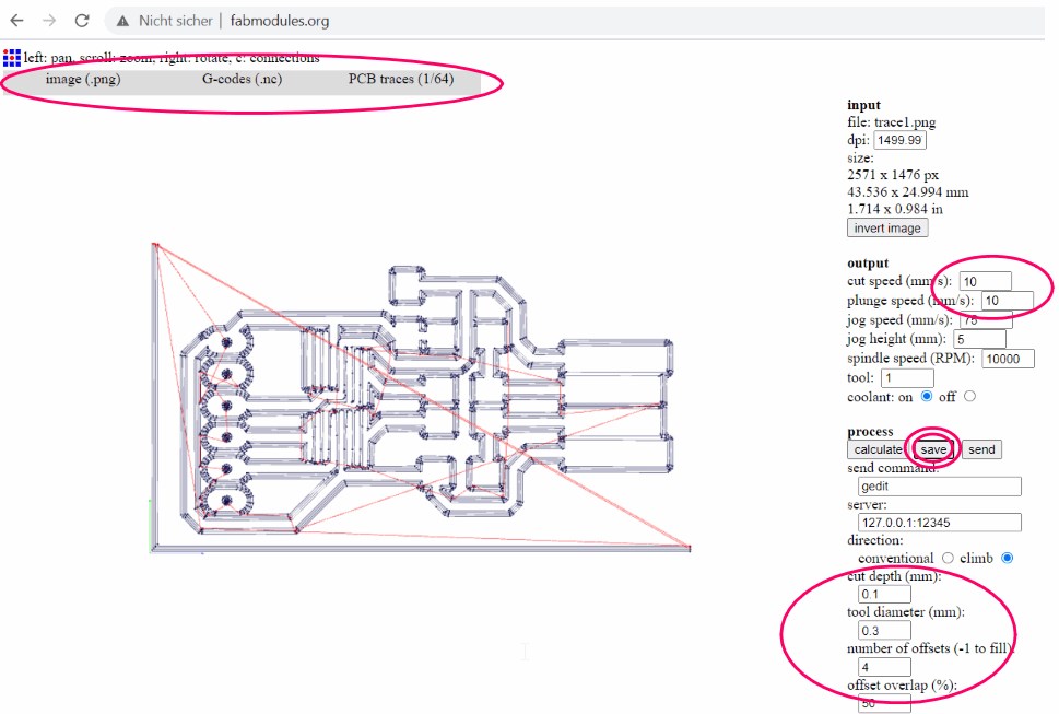
Since a white residue has remained at the bottom and right, an angle will be made which is not necessary.
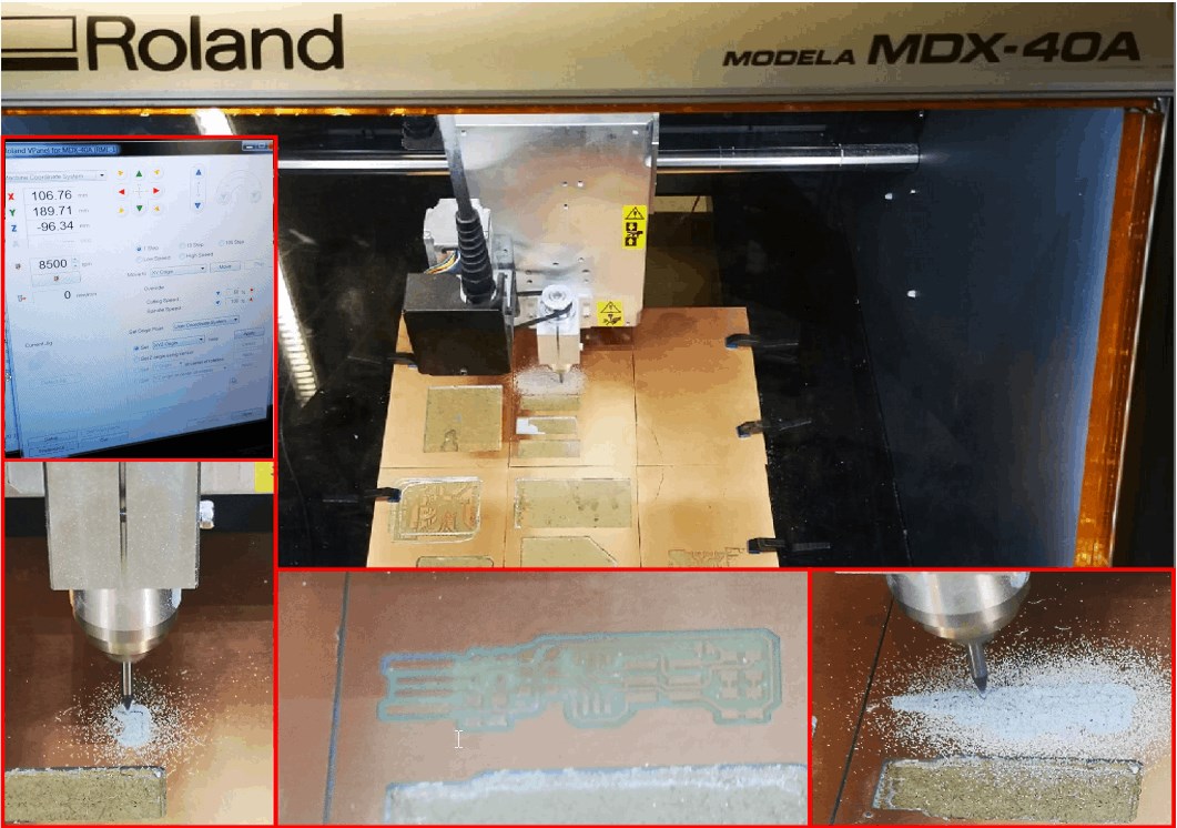
milling the updi board
I then create the gcodes for the updi board with the same process and start the milling work.
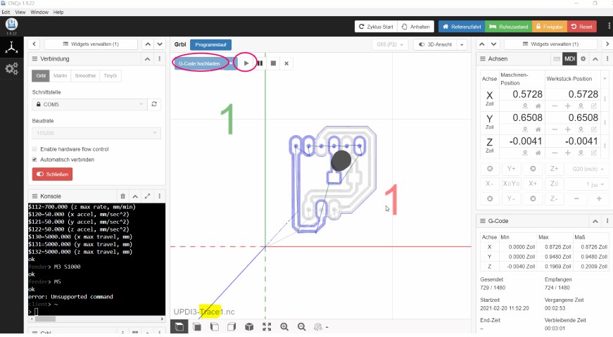
I load the gcode obtained in this way into CNCjs and start the job.
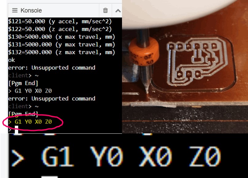
In order to align the machine again exactly for the holes, I set the spindle back to zero.
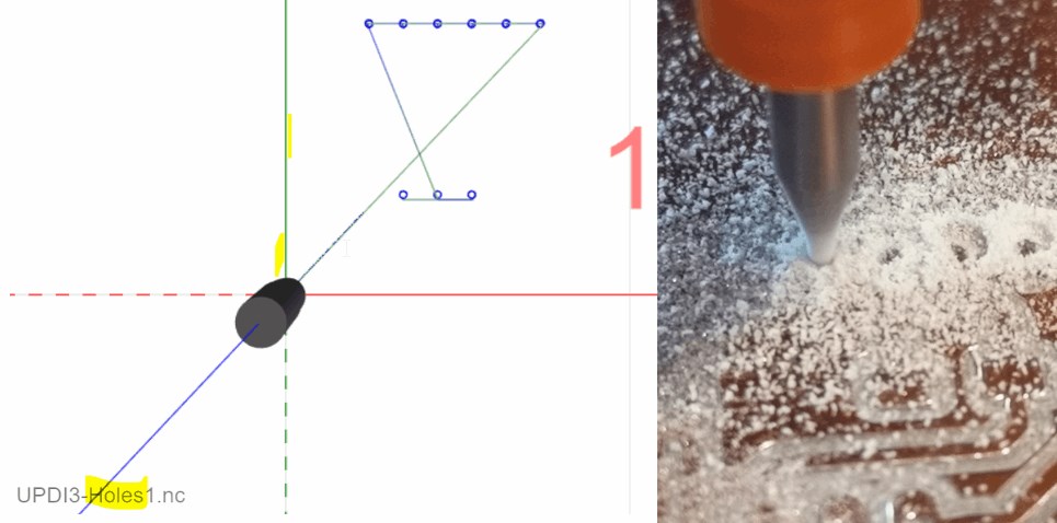
Now I’m starting the next job. The holes should be milled before the cutout so that nothing shifts.
For the next job I set everything to zero again.
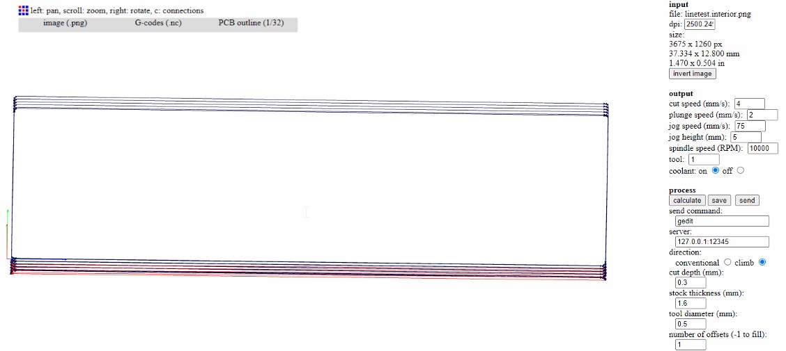
Now comes the cutout.
I have already done the same process for the FTDI board.
rework manually
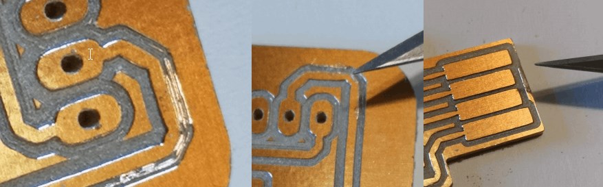
At one point or another I have to rework manually.
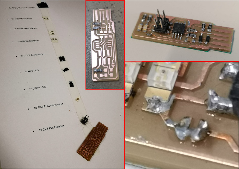
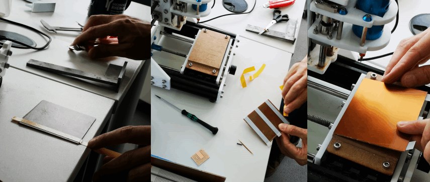
soldering
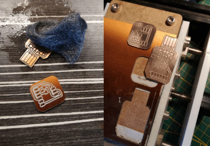
I go over the surface with water and steel wool so that the solder adheres better.
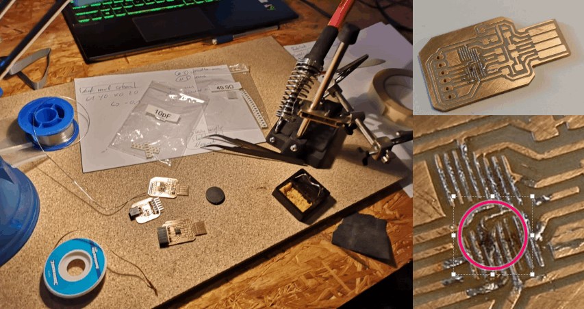
The attempt to first apply some solder to the surface of the microcontroller, and then to put it on and melt it, failed. The fine connections have separated.
The second attempt works better.
the HalloD1614 board
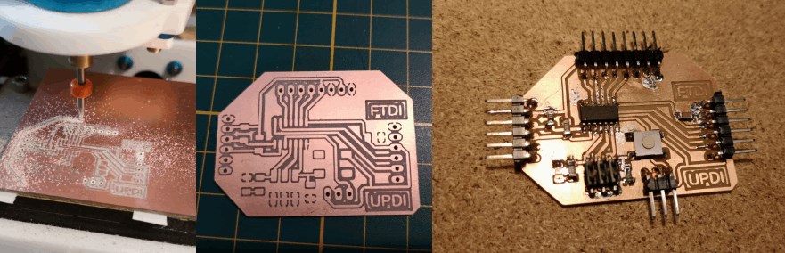
I make the HalloD1614 as the last board. Again with the above-described procedure.
check the FTDI-USB board in the device manager
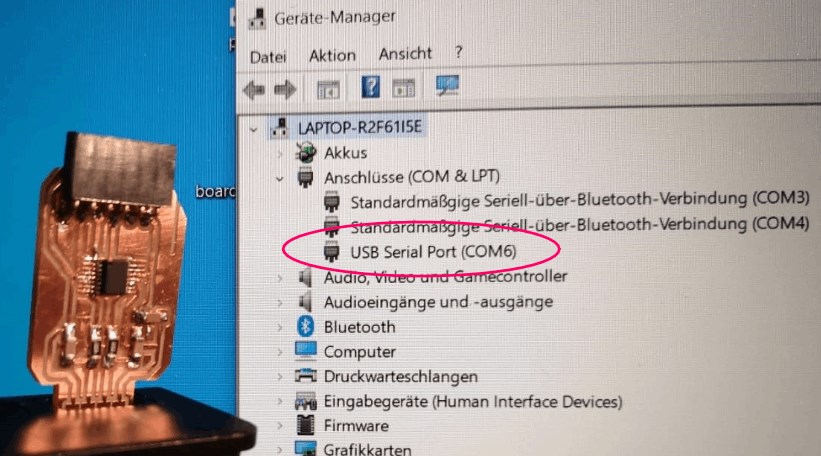
To see whether the computer recognizes the FTDI-USB board, I connect it to the computer via usb and check the device manager to see whether it is recognized. I can find it under USB Serial Port (COM6).
Brians FabISP
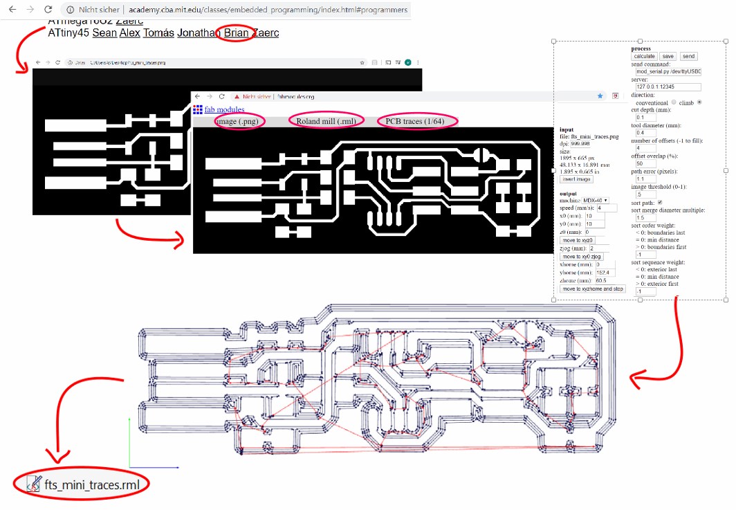
In order to be able to mill an in-circuit programmer, I first decided on the model from Brian on the Fabacademy site. Here I downloaded two PNG files with a resolution of 1000dpi and uploaded them to fabmodules in order to determine the conductor paths
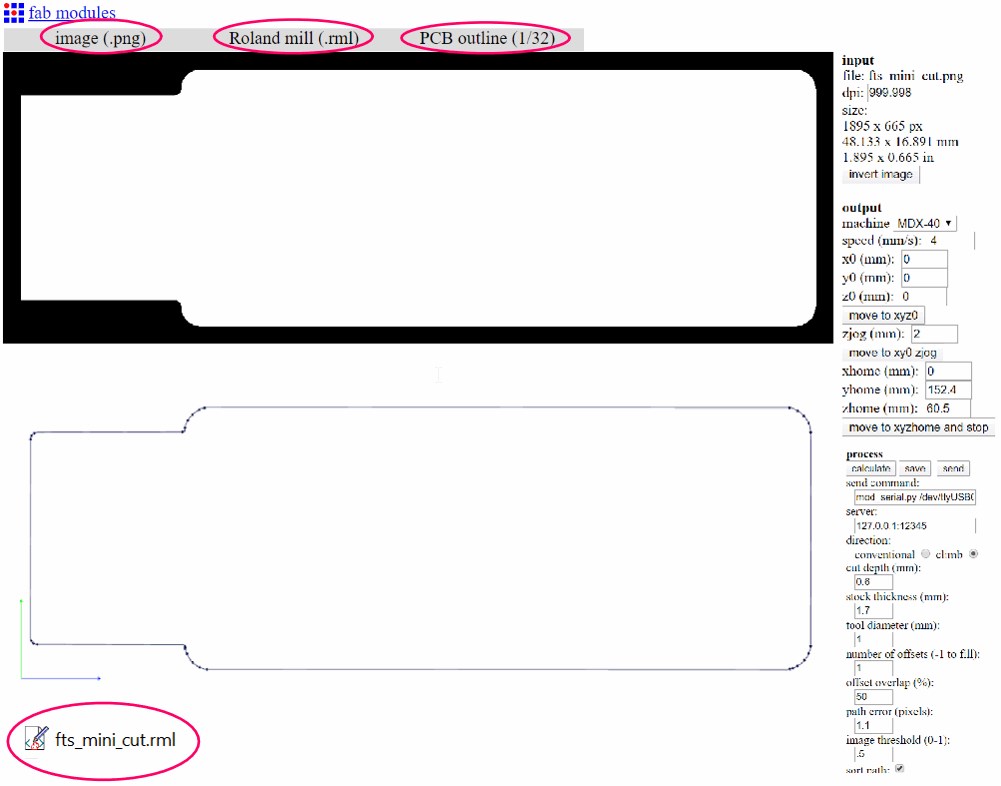
and on the other hand to generate the outline or the section.
With the machine code obtained in this way, I was able to create the conductor tracks with a tool diameter of 0.4mm and cut out the outline with a tool diameter of one mm.
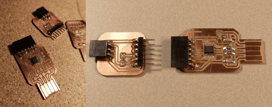
The next step is to solder the various components onto the printed circuit board / PCB. A bridge is created here (bottom right) so that the programmer can be programmed. So that the programmer is not accidentally changed or programmed differently afterwards, the bridge is then removed again.
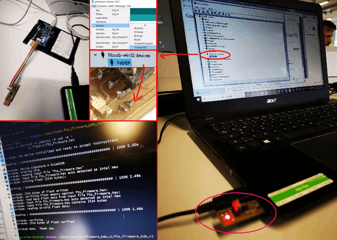
First I programmed the Arduino with the programmer, i.e. made it a programmer. Then uploaded the .hex file (fts_firmware.hex) to the copied programmer via git bash via the programmer (Arduino).
The process was successful if the programmer is displayed in the device manager. The bridge can now be removed and the programmer can be used.
group
the machine
Buy the machine

Prepare the machine.
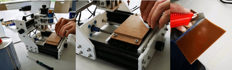
Test the machine.
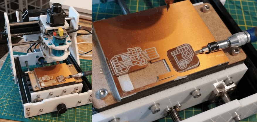
We create the gcode in fabmoduleswith this settings,
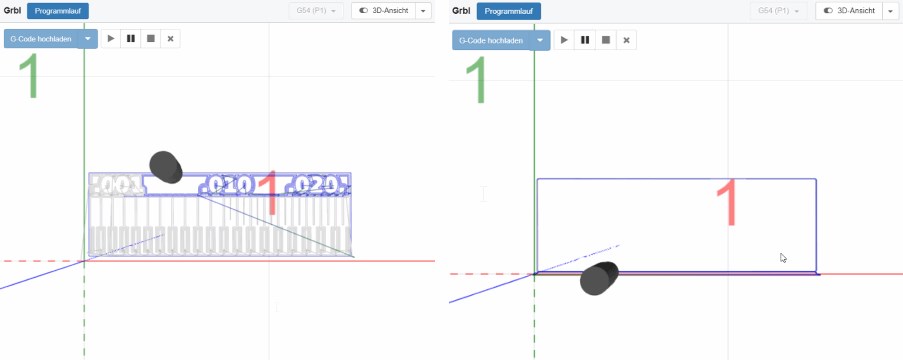
send it with cncjs to the machine
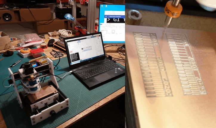
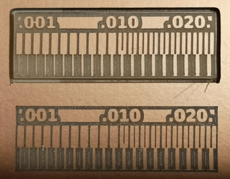
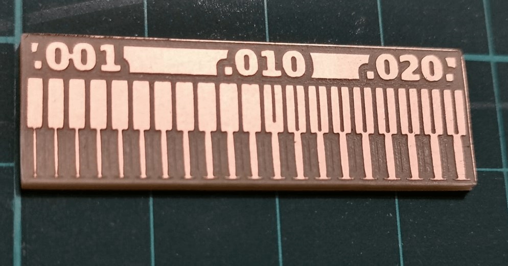
and get this result.
The following link shows the group assignment site.