4. Electronics Design#
-
Group assignment:
-
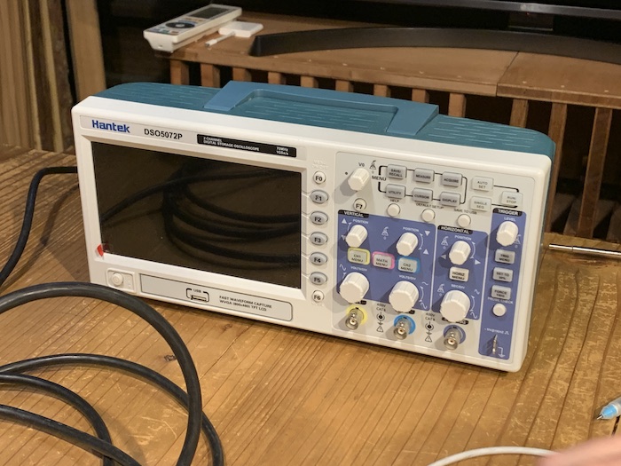
Use the test equipment in your lab to observe the operation of a microcontroller circuit board (in minimum, check operating voltage on the board with multimeter or voltmeter and use oscilloscope to check noise of operating voltage and interpret a data signal)
- Document your work (in a group or individually)
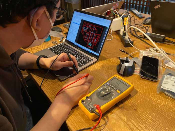
A multi-tester can be used to measure current flow, voltage drop, and resistance value. To make sure that the circuit you have created is working properly, apply the two probes to the necessary points.
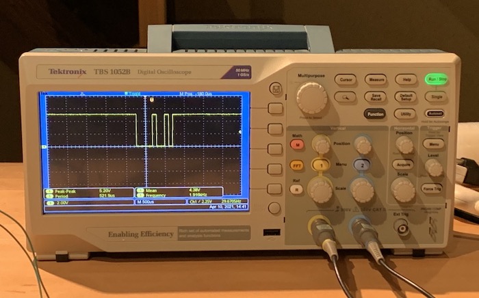
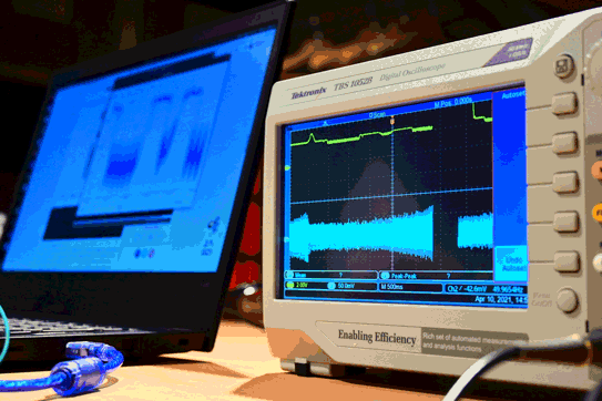
From Arduino, we sent digital signal, char data. In this case, it shows H = 01001000 from left to right. Upper lines means 1, lower lines means 0.
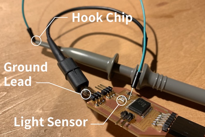
Try to probe light sensor’s analog signal. Connect the copper line to the microcontroller and the hook chip with lead wires, also ground lead to the ground.