Input Devices
During this week (week 10) I worked on designing an EMG or myosensor for the muscles, which was not completed and therefore not produced. The sensor was going to be used in my original final project. All the efforts to do this have been documented in detail in this page.
Later, in week 13, I ended up working on other input devices, IR receivers (obtained from some old TV circuits) and a DHT 11 temperature/humidity sensor. They worked wonderfully and became part of my final project. Since these were used starting in week 13, while there is some information available on this page, more details about these input devices can be read in week 13 and 14.
Designing a myosensor
This week was all about various types of sensors, which are the input devices for any PCB in need, and was of utmost importance for my final project, which is a hand prosthesis.
The group assignment for this week was to find out an input device's analog levels and digital signals, which can be viewed in the corresponding group assignment page.
For the hand prosthesis, I need to develop myoelectric sensors.
Research and literature review
I did quite a bit of research for this. I consulted the following sources to come up with my design:
- Anatomical and medical books;
- Talking with an EMG specialist;
- Papers on EMG sensor boards and diagrams;
- Lots of youTube videos explaining about EMG signals and the processing needed.
Here is a list of books available on anatomy of an arm, the nerves within, and the EMG signal obtaining and processing:
- Joint Structure and Function: A Comprehensive Analysis by Levangie and Norkin
- Electromyography and Neuromuscular Disorders by Preston and Shapiro
- Cram's Introduction to Surface Electromyography by Criswell
- Atlas of Muscle Innervation Zones: Understanding Surface Electromyography and Its Applications by Barbero et al
- Oxford Textbook of Clinical Neurophysiology


I was very thankful for meeting with Dr. Christine Sabahgoulian. I learned that they perform electromyography through internal electrodes, but moslty use the same device (NTS-2000 portable EMG System) for performing Nerve Conduction Studies. These methods are mainly used to diagnose neuromuscular disorders.
The internal electrodes used to pick up muscle signals pick up the signal the best through their tip; therefore, if the tip is at a muscle fibril, it'll pick up a better signal than inside a muscle, but not at a fibril; on the other hand, it'll pick up a higher amplified signal if at a fibril bundle rather than at a single fibril. This is all food for thought on how much less amplified the signal picked up by an external electrode would be. Also, there are questions associated with how much less of a signal a dry electrode picks up compared with a wet one. More on types of the electrodes can be read at the electrodes section.
Dr. Sabahgoulian also showcased how the EMG is read by the NTS-2000 using external electrodes, and we performed a few experiments to see how grounding the body connected to the electrodes in various ways affected the signal that the device would output. Furthermore, she provided me with Ambu tabs to use as electrodes in addition to the H99LG Covidien Arbo electrodes that I had previously procured. She also recommended a few books and their relevant pages which I have referenced above.
The electromyography (EMG) signal
In Delsys's Surface Electromyography: Detection and Recording the EMG signal's amplitude is stochastic (random) in nature and can be reasonably represented by a Gausian distribution function. The amplitude of the signal can range from 0 to 10 mV (peak-to-peak) or 0 to 1.5 mV (rms). The usable energy of the signal is limited to the 0 to 500 Hz frequency range, with the dominant energy being in the 50-150 Hz range.
Electrodes
The electrodes used for electromyography can be divided into two main groups:
- External electrodes
- Internal electrodes
The external electrodes are placed on the skin and can be themselves divided into:
- Wet electrodes
- Dry electrodes
Designing the sensor
An electromyography sensor is basically a potential (voltage) sensor for the muscles, with amplifiers to amplify the magnitude of the signal, filters for the noise, and if the signal is to be connected to a computer or a processor, then it should also go through an analog to digital converter (ADC) as well. Electromyography signal is basically the different between the voltages of mid-muscle (e.g. the bicep muscle) and its end (e.g. over the tendon). These are picked up by electrodes as was described in the electrodes section. A reference voltage is also needed for processing the noise; this can be obtained by placing a third electrode on a bony surface such as on the elbow.
Once a sensor is developed, a more advanced solution would be to put a number of them (e.g. 8) in a ring to be worn around the arm, like some existing myoelectric armbands that are mentioned on the final project page. A paper entitled Open Source Multichannel EMG Armband design by Ossaba et al tries to tackle this issue.
When it comes to the sensor design itself, there were multiple very helpful videos. Here is one that I found particularly helpful by Jimmy Dieffenderfer:
Here's another video that was very helpful in its explanations:
Also, from Advancer Technologies who are the makers of MyoWare Muscle Sensor which was also mentioned on the final project page comes this Instructible's page which was also very good.
One can further look at this video, and this or this instruction set for more information.
And just to keep this reference for later on as well, here's what one can learn from the teardown of a Thalmic Labs Myo Armband by Limor Fried herself: (its I IP currently held by Facebook, Inc.)
Before starting, here is the best reference for working with OpAmps: Op Amps for Everyone by Ron Mancini
And a useful guide: Electronics 101 by Duval
And here's what I learned about designing a single-supply EMG (similar to EEG and EKG) in a nutshell:
Any circuit that takes signals from the body and makes an analog signal from it is mainly comprised of these 3 stages:
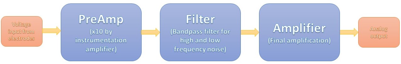
The pre-amplification stage
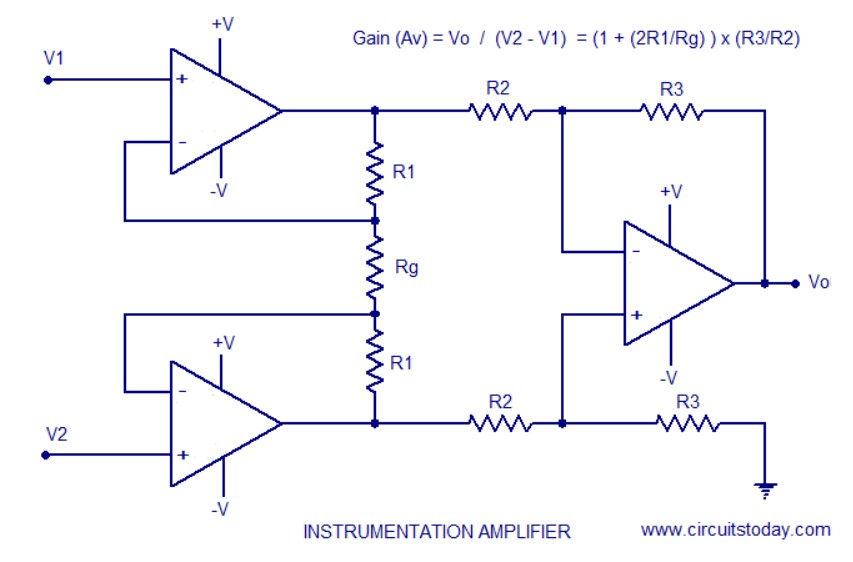
For EMG or any circuit you want the PreAmp to not draw current from the body since the body is high impedence; therefore, the PreAmp should have a high input impedence. That is why an Instrumentation Amplifier is a differential amplifier (a type of electronic amplifier that amplifies the difference between two input voltages but suppresses any voltage common to the two inputs) that has input buffer amplifiers, which eliminate the need for input impedance matching and thus make the amplifier particularly suitable for use in measurement and test equipment.
Here's what the diagram of a typical instrumentaion amplifier looks like: (the RG in the subsequent diagrams refers to the Gain resistance)
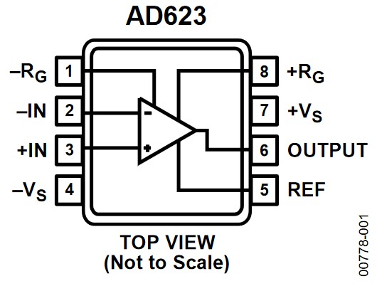
The video of Jimmy Dieffenderfer suggested to use INA118 or AD623 for the Instrumentation amplifier. My eventual intention would be to use AVR128DB32 per Neil's suggestion, which has three operational amplifiers inside which can be configured to act as an instrumentation amplier; however, at the moment I only had access to AD623 through Ռադիոսիրող, so that's what I'll be using. It should be mentioned that this component is a through-hole component; so I'll be bending the pins and playing around with KiCad to be able to solder it as an SMD component.
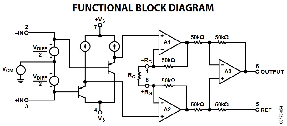
Here's the diagram of what's inside the AD623:
And here's how the pins of AD623 are configured:
In the NTS-2000 system that I observed the black electrode was connected to the belly of the muscle; so I will assume that the - signal should be coming from the muscle belly.
Calculation
The gain of an instrumentaion amplifier can be calculated as follows: (the resistor numbers correspond to the initial InsAmp diagram)
G=(R3/R2)*(2R1+RG)/RG
In AD623 as can be seen from the functional diagram, R1=R2=R3=50 kΩ.
Therefore, for a gain of 10, RG=11 kΩ, so I can use a 10 kΩ and 1 kΩ resistor in series, or use a 10 kΩ resistor and opt for a gain of 11. I'll choose the latter, as I don't believe the exact amount of the gain to be critical, and will therefore choose simplicity.
The filter stage
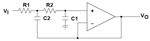
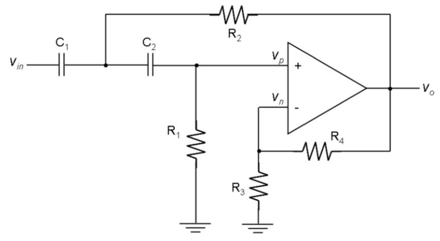
An EMG circuit uses an active filter, which means it'll using OpAmp's instead of just passive components such as resistors and capacitors. For this, Dieffenderfer recommends using a 2nd order Sallen-Key filter, which is an active filter design architecture valued for its simplicity. Both high and low frequency filters can be designed in this way.
Here are what a typical 2nd order Sallen-Key low (left) and high-pass (right) filter look like:
For OpAmp's for the filter I had the choice of using either AD8605 (10MHz, SOT23-5) or AD8615 (24MHz, TSOT23-5) based on availability in the lab.
If a high-pass and a low-pass filter are going to be used, the output of one should be fed into the input of the other; in other words, they should be connected in series. The values of the components of the filter should be selected based on what cut-off frequency is needed. Texas Instruments has an online filter design tool that can be useful in calculating what components are needed.
Calculation
The band-pass filters should filter the signal between 0-500 Hz as described in the EMG section.
For calculating the component values for a 2nd order Sallen-Key low-pass filter, I used Okawa Electric Design's Sallen-Key Low Pass Filter Design Tool.
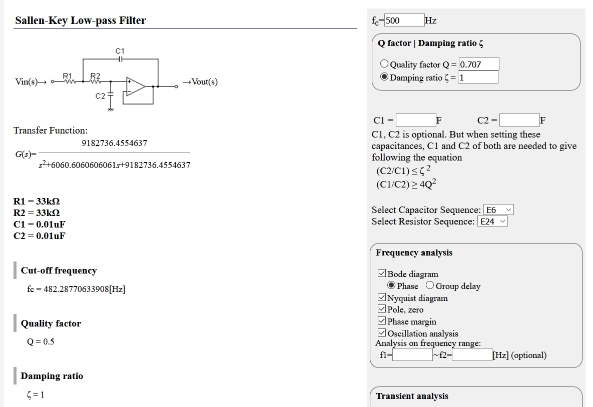
As can be seen, R1=R2=33 kΩ and C1=C2=0.01 μF. Since we didn't have 33 kΩ resistors at the lab, the choice was to either have three 10 kΩ and three 1 kΩ resistors in series, or have a 100 kΩ and 50 kΩ resistor in parallel, resulting in a 33.33 kΩ resistor. We didn't have 100 kΩ resistors either, so I can use two 50 kΩ resistors in series in parallel with another 50 kΩ resistor.
This will cause the final resistors to be 33.33 kΩ instead of 33 kΩ, which means the cut-off frequency is actually going to be 477 Hz.
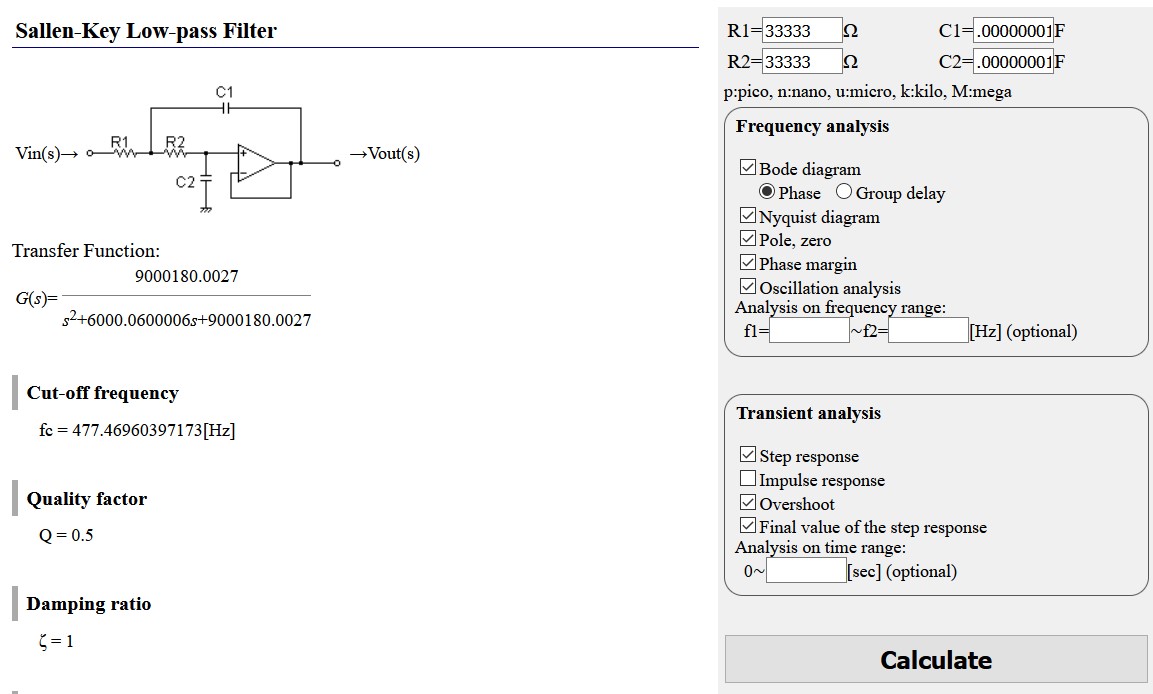
I'll be skipping having a high-pass filter as will be looking at the full range between 0-477 Hz.
The final amplification stage
The last stage to producing an analog signal is a non-inverting OpAmp circuit. A non-inverting amplifier is an op-amp circuit configuration that produces an amplified output signal, which is in-phase with the input signal.
Calculation
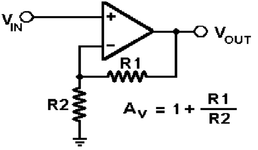
Gain from the non-inverting amplifier can be calculated as AV=1+R1/R2.
So a gain of 201 can be obtained if R1=1 MΩ and R2=5 kΩ, and a gain of 101 with R1=1 MΩ and R2=10 kΩ
.Considering that the potential from the muscles is going to be between 0-10 mV, and has already had a gain of 10 from the pre-amplifier, it should be amplified such that the output is no more than 5 V since it'll be fed to ATtiny45 and a potential of half a point above that range can kill the processor. That means that the 10 mV signal which after a gain of 10 would be 100 mV should not be amplified to no more than 5 V, which is a gain of 50. So R1=50 Ω and R2=1 Ω will ensure a gain of 51.
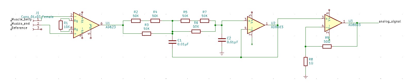
Here's what the current design looks like with the pre-amplifier, low-pass filter, and final amplifier:
Analog to digital conversion (ADC)
I will be using an ATtiny45 which we have available in the lab for the analog to digital conversion. It is capacble of ADC as well as amplification of the signal from 1 to 20x, so I could potentially forego of the previous step, except I calculted a gain of 50 for having the maximum myo signal amplified to 5 V, so the gain of the ATtiny45 will just not be enough.
The ADC connection pins can be seen in the ATtiny45 diagram below:
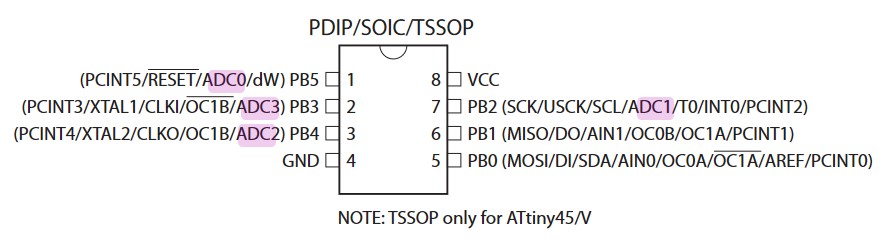
The ADC of ATTiny45 converts an analog input voltage to a 10-bit digital value through successive approximation. The mini-mum value represents GND and the maximum value represents the voltage on VCC, the voltage on the AREF pin or an internal 1.1 V / 2.56 V voltage reference.
Any of thefour ADC input pins ADC[3:0] can be selected as single ended inputs to the ADC. ADC2 or ADC0 can be selectedas positive input and ADC0, ADC1, ADC2 or ADC3 can be selected as negative input to the differential gain amplifier.
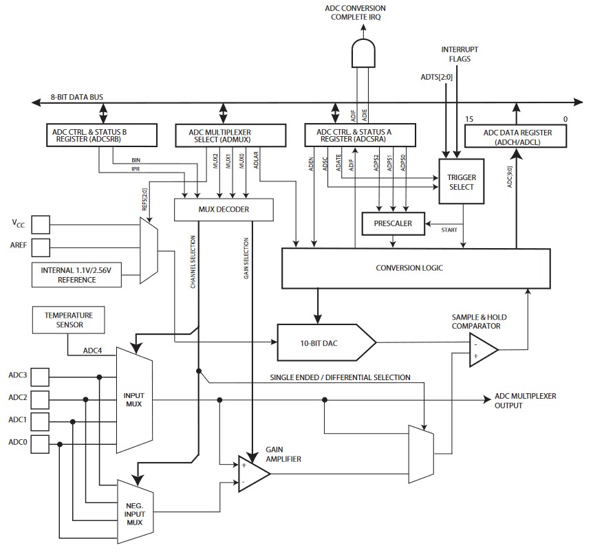
In order to not use the gain function, single ended channels can be used, so that the gain amplifier is bypassed altogether.
Here's the block schematic of the ADC inside the ATtiny45:
Since the design for the EMG sensor was not finalized, I did not proceed to make it. Rather, I got to play around with other input devices in the coming weeks that I've documented below.
Other input devices
For my final project, I ended up doing a Universal Remote Control, which uses an IR receiver to decode various remote controls, and uses a CHQ1838 IR receiver to decode the infrared codes received from various remote controls, and a DHT11 temperature/humidity sensor. The use of both will be described below.
Both of these devices were used for the first time in week 14 (Interfaces), so a more original account can be found there.
Using an IR receiver
Initially, I had a lot of problem trying to purchase an IR receiver, as I couldn't find any at the stores or online. So thanks to the husband of my nanny in Dilijan, I was able to obtain 3 used infrared receivers from some old TV IC boards. I want to express my deep gratitude to all the individuals who made this happen.
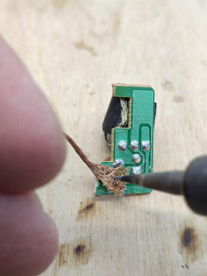
I had to 'unsolder' and detach the IR receivers, of course. So here's the trick I came up with: Take the copper solder wick and put it on flux and heat it up a bit for it to absorb some flux:

Then take that wick and use it to pull up solder from the old boards. It worked like a charm:
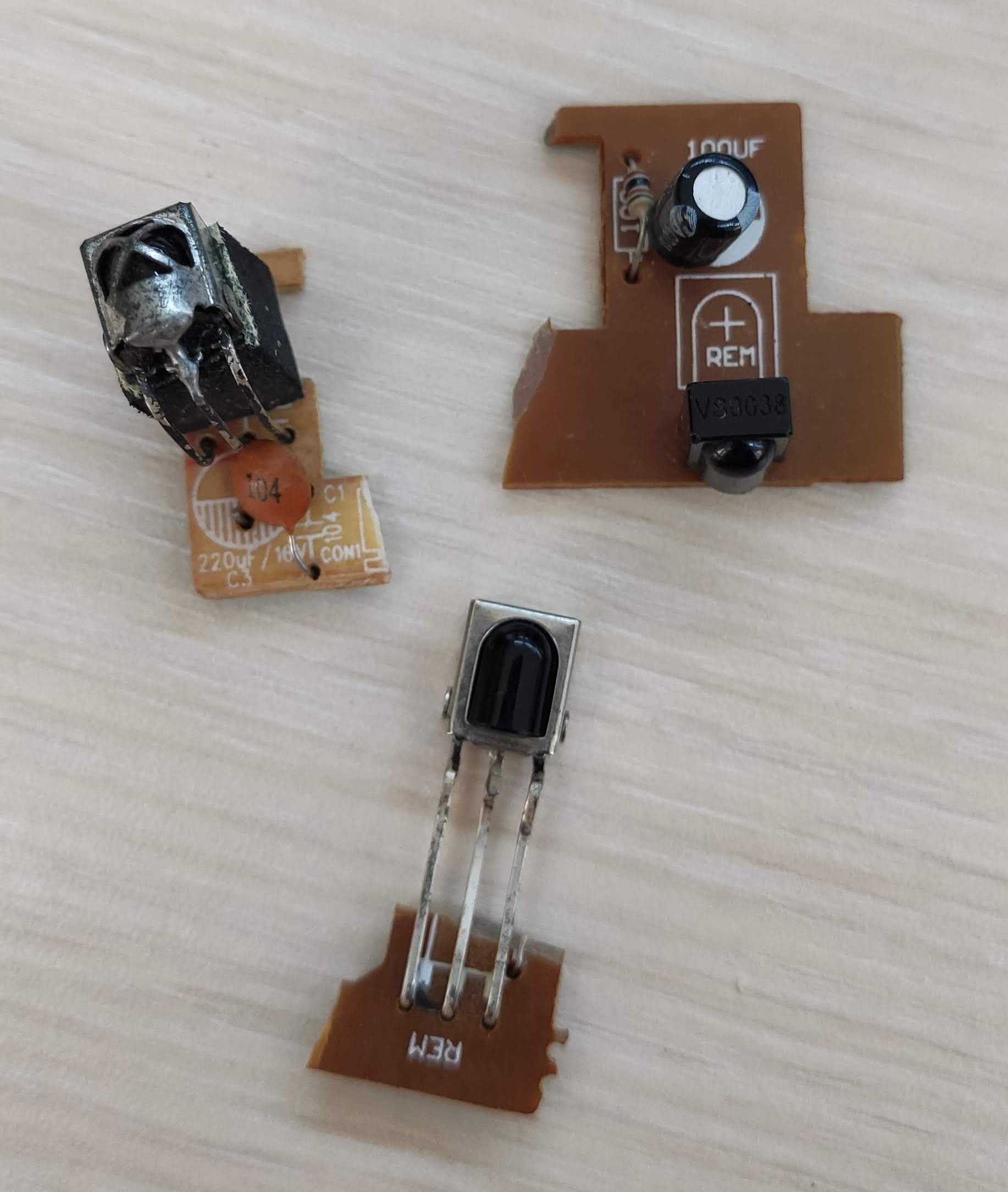
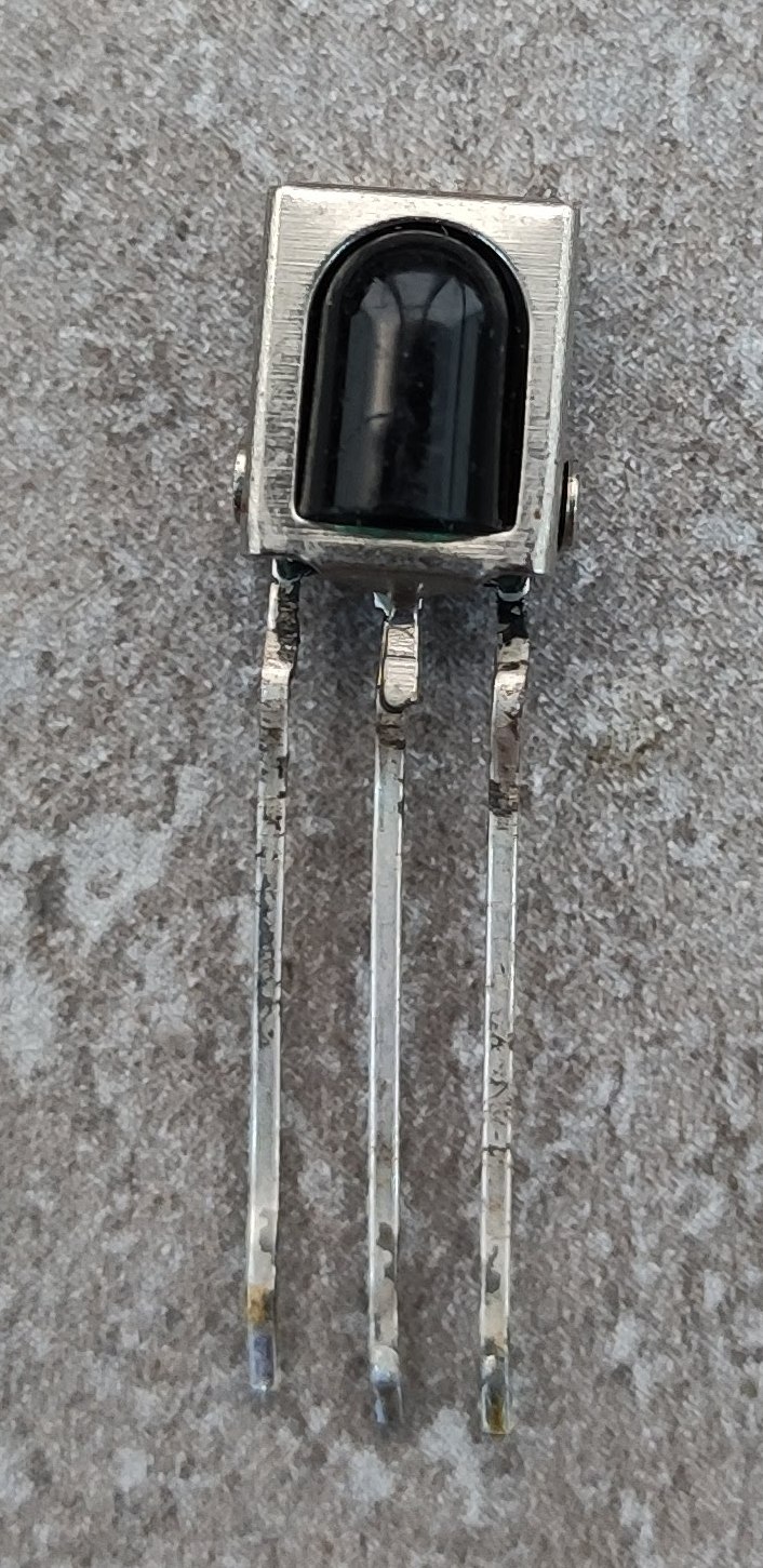
So I ended up with a beautiful CHQ1838 IR receiver, which I didn't know whether worked or not:
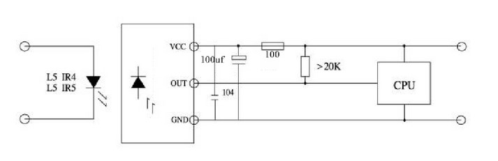
I found a little Chinese datasheet with the pin configuration of the receiver.
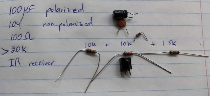
And the datasheet also had an application circuit diagram for the IR receiver, which interestingly, was very similar to the way the receivers were set up on the boards I recevied; and to the credit of the electrician who passed them off to me, he had included those parts, which included a polarized 100 μF capacitor and a non-polarized 100 nF capacitor that were connecting VCC to GND in parallel, so I think those were decoupling capacitors (why is one polarized and the other not? Still don't know.) There was also a 20 kΩ pull-up resistor:
I ended up 'desoldering' the other components from the old IR receiver boards as well to use in my own circuit:
Testing the IR receiver
In order to test whether the old IR receivers I now possessed were working, I found the following setup from Adafruit:
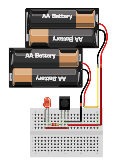
I hooked up each receiver to an Arduino Uno board and tested whether it would light on if I pointed a remote control at it and pressed a button, which would send an infrared signal to it.
The following images show the CHQ1838 receiver working fine, with the green LED turning on as the remote transmits infrared codes to the receiver:
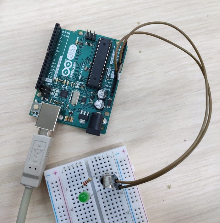
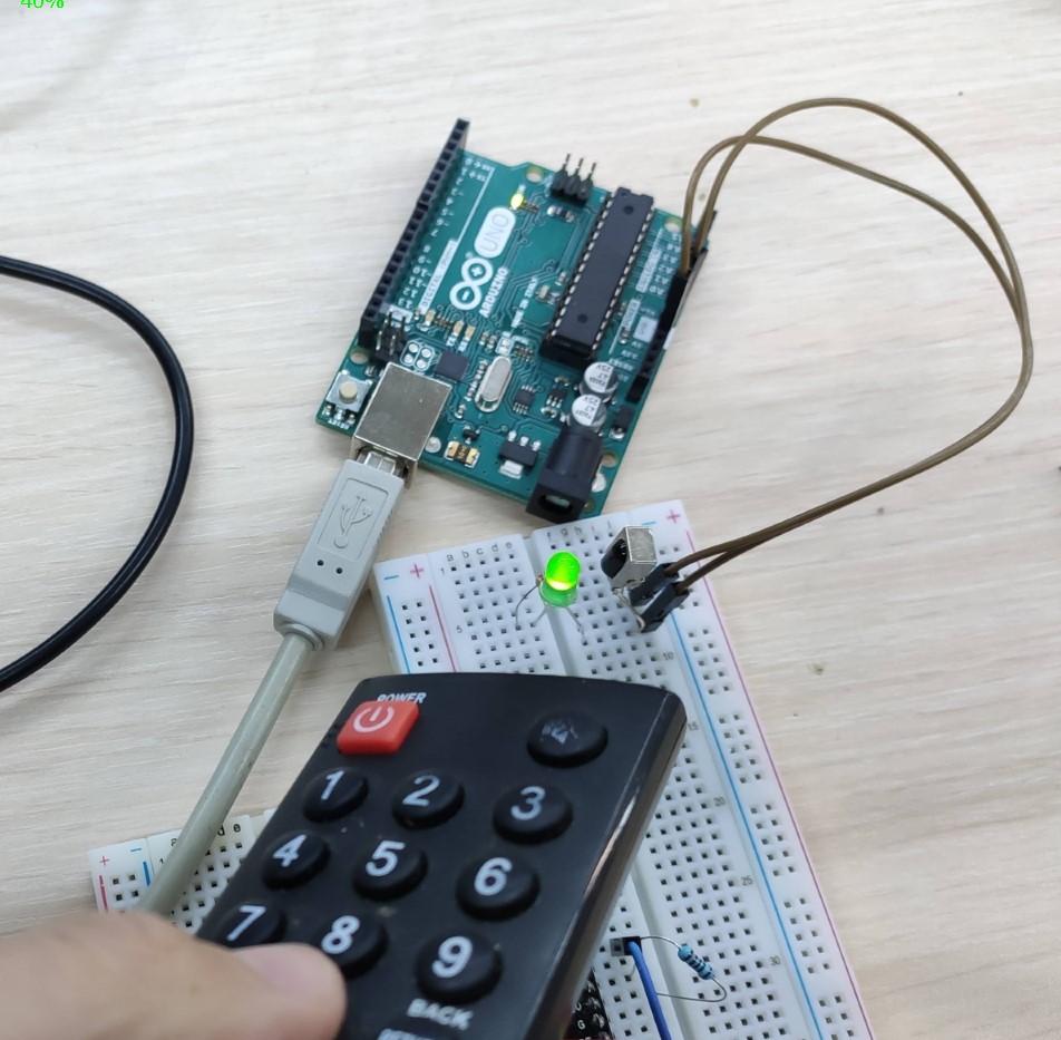
For an account of troubleshooting the problems associated with the IR receivers, please see week 14.
Programming ESP8266 microcontroller to work with the IR receiver
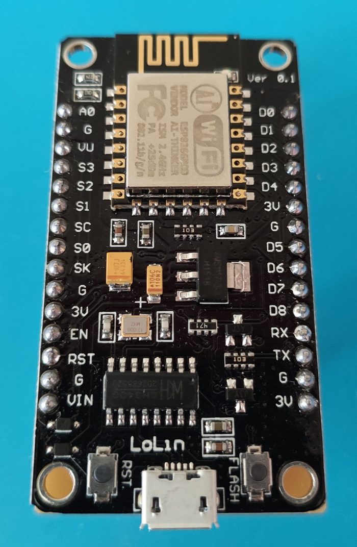
I wanted to hook up the IR receiver with an ESP8266 wifi module/microcontroller to be able to decode the infrared codes transmitted to it from any remote control. My husband had given me the LOLin new NodeMCU v3 breakout board with an ESP8266 wifi module/microcontroller, which I wanted to use.
Something important that should be mentioned is that there are two types of infrared receivers:
- 2-pin IR transistors: Here the anode is connected to the VCC and the cathode is the data pin. It should be hooked up similar to this. It is moslty useful for detecting whether there is an IR signal or not, so is useful in something like a reflection obstract sensor.
- 3-pin IR receivers: These have a VCC, GND, and data pin, and are more useful in decoding IR signals.
Here's the pin configuration of the CHQ1838 receiver:
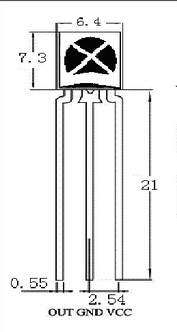
As can be seen from the image (and this is not shared among all IR receviers), the left pin is the data pin, the middle pin is the ground pin, and the right pin is the VCC.
In case of the NodeMCU breakout board that I had, I hooked up the data pin of the IR receiver to D5, which is connected to GPIO (general-purpose input/output) pin number 14 of the ESP8266.
The receiver was originally set up on a breadboard and tested to see whether it works with NodeMCU, until later a board was designed to connect to the NodeMCU with the IR receiver and other input and output device embedded on it.
The NodeMCU board can be programmed through a direct micro-USB connection with the computer, using a program such as the Arduino IDE. No special programmer is needed for prgoramming the NodeMCU.
In order to program a decoder for the IR receiver, there is a useful library written for use with the Arduino IDE named IRremoteESP8266.
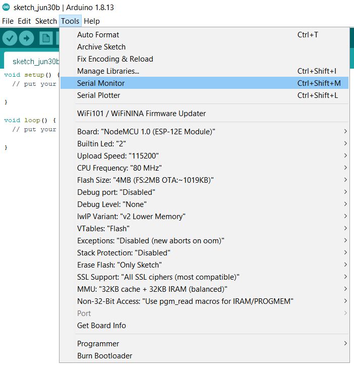
In order to install the library, open the Arduino library and go to Tools -> Manage Libraries...
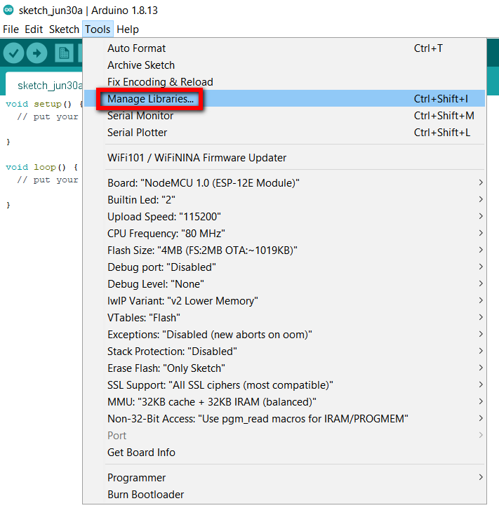
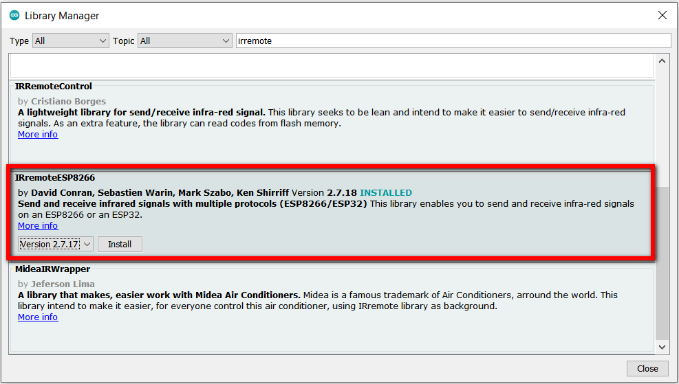
Search for 'IRremoteESP8266' partially or in full, and the following library should show up. Install the library:
Once the library is installed, the board can be programmed. Connect the board to the computer using a micro-USB. Make sure
the computer recognizes the board by checking the Device Manager on Windows; this can be accomplished by
right-clicking the Windows icon and choosing Device Manager. If the Device Manager does not show any
connection, it might be because the USB connection is hidden. In order to show all connections, in the Device Manager
window click on View -> Show hidden devices. If the device still doesn't show up, Windows might be missing
the appropriate driver and the problem
can be fixed by installing it. More about this and troubleshooting can be read in the
week 13 assignment.
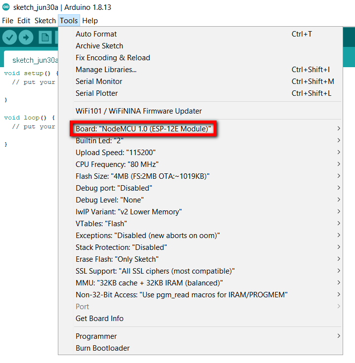
Once the board is connected and recognized in Device Manager, you can check what port it is connected to in the
Device Manager to be able to use it in Arduino IDE for the programming. The appropriate board and port
should be selected under Tools in the Arduino IDE:
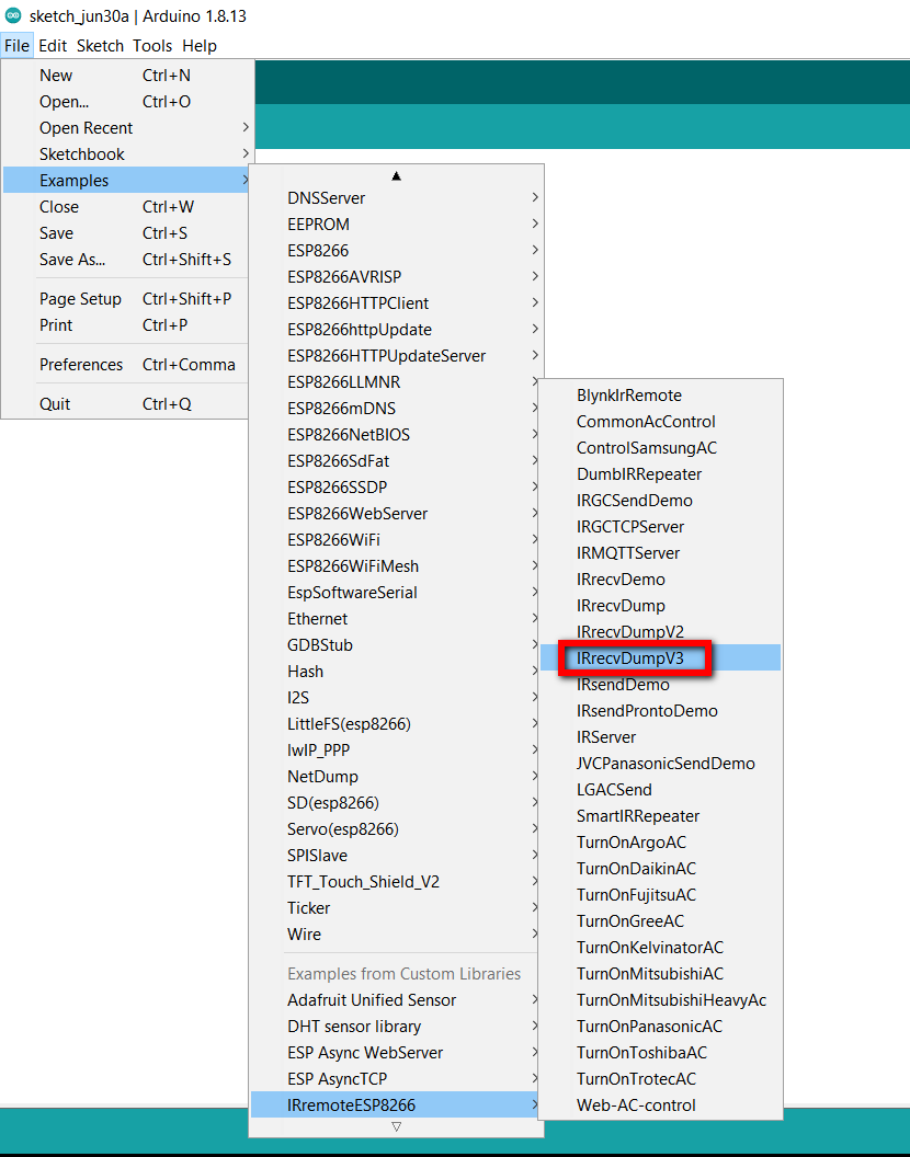
An example program to read input from the IR receivers comes with the IRremoteESP8266 library; this can be
summoned in Arduino IDE by going to File -> Examples -> IRremoteESP8266 (under Examples from Custom Libraries) -> IRrecvDumpV3.
There are older versions of this example file as well, which may not work properly, so V3 is recommended.
Check the file to make sure the right pin connection is selected (GPIO 14 of ESP8266 or D5 on NodeMCU). You can then
go ahead and hit the Upload button and watch the program be transferred to the ESP8266 microcontroller
on you NodeMCU board.
Once finished, you can test it by opening the serial monitor of the Arduino IDE:
Now try pointing any remote to your IR receiver, hit a button, and watch the code unfold on the serial monitor. You can test as many remotes as you wish, and in the end copy and paste all the code in a text file log if you'd like to use the codes later.
Here's one example of the IR codes decoded by my IR receiver that were gathered in a text file by copy-pasting them from the serial monitor of Arduino IDE. They decode the codes from a Berg TV remote:
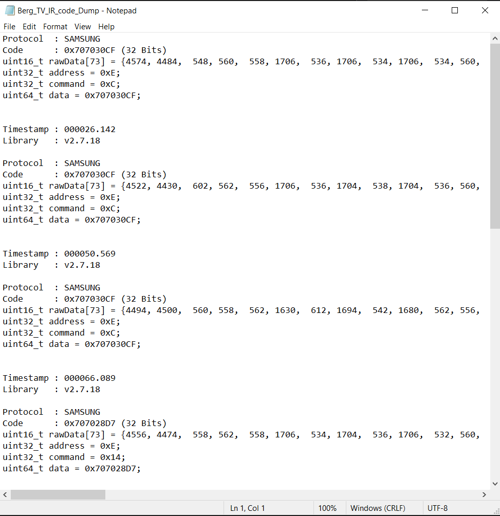
The Arduino file was slightly modified to account for the right pin of the NodeMCU and can be found at the bottom of the page.
There are some online IR databases for various devices. It is notable that the IRremoteESP8266 library has specific library files for Samsung, Daikin, Mitsubishi, Panasonic, Toshiba, and other air conditioner control codes.
Using the DHT11 temperature/humidity sensor
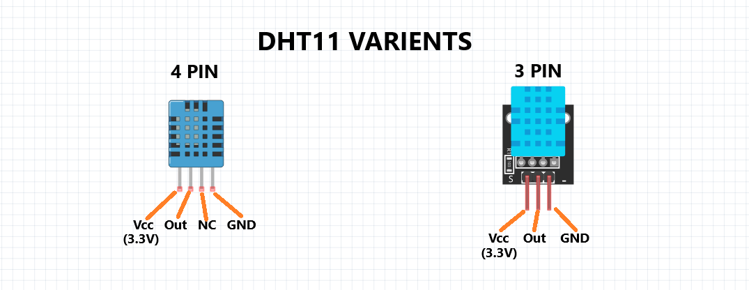
DHT's are low-cost temperature and humidity sensors with a capacitive humidity sensor and a thermistor. Inside there is also a chip that does analog to digital conversion and outputs the temperature and humidity as digital signals. DHT11 and DHT22 are popular models of those:
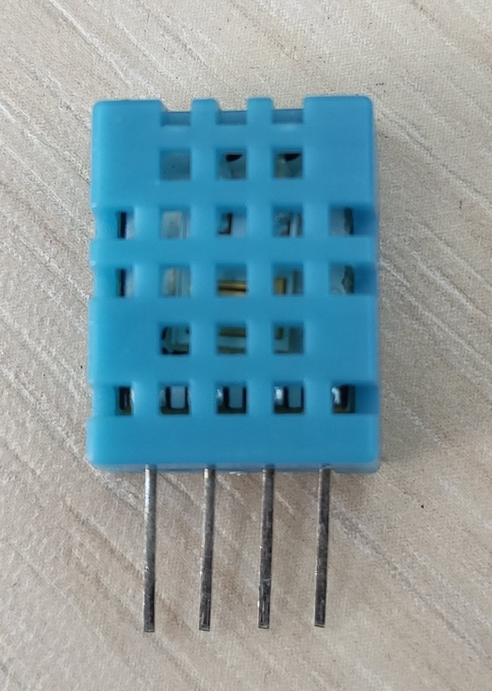
I decided to use DHT11 due to its availability:
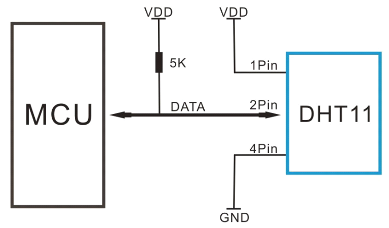
As can be seen from the DHT11 datasheet, of the 4 pins of the sensor, the left pin (looking from the front) is connected to VCC, the second is connected to the data input of the microcontroller, and the 4th pin is connected to GND. The 3rd pin seems unused, but in order to prevent it from floating, it can also be connected to the 4th pin (hence GND). Here's a typical configuration of how the sensor is set up from the datasheet:
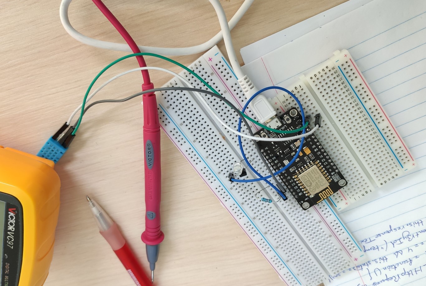
The DHT11 was initially set up on the breadboard to see whether it works:
The programming part is very similar to the IR receiver above; as I was going to use the DHT11 in conjunction with the NodeMCU breakout board with its ESP8266 wifi module/microcontroller, I wanted to connect the data pin to pin D4 of the NodeMCU board, equivalent to the GPIO 2 of ESP8266.
Again, the NodeMCU board can be programmed by a simple micro-USB connection to the computer, not requiring
any special programmer (oh, the beauty!). And Arduino IDE is just fine for the job of the software. Again, the
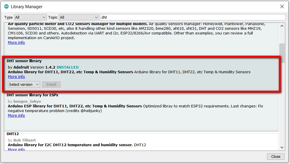
Arduino IDE has a special library for handling work with DHT11 and DHT22 sensors. The library is called
DHT sensor library and can be installed through Manage Libraries.... It may
require additional installation of Adafruit Unified Sensor library as well.
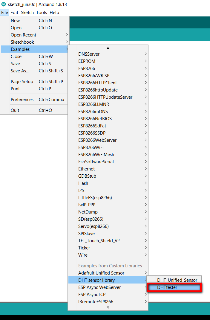
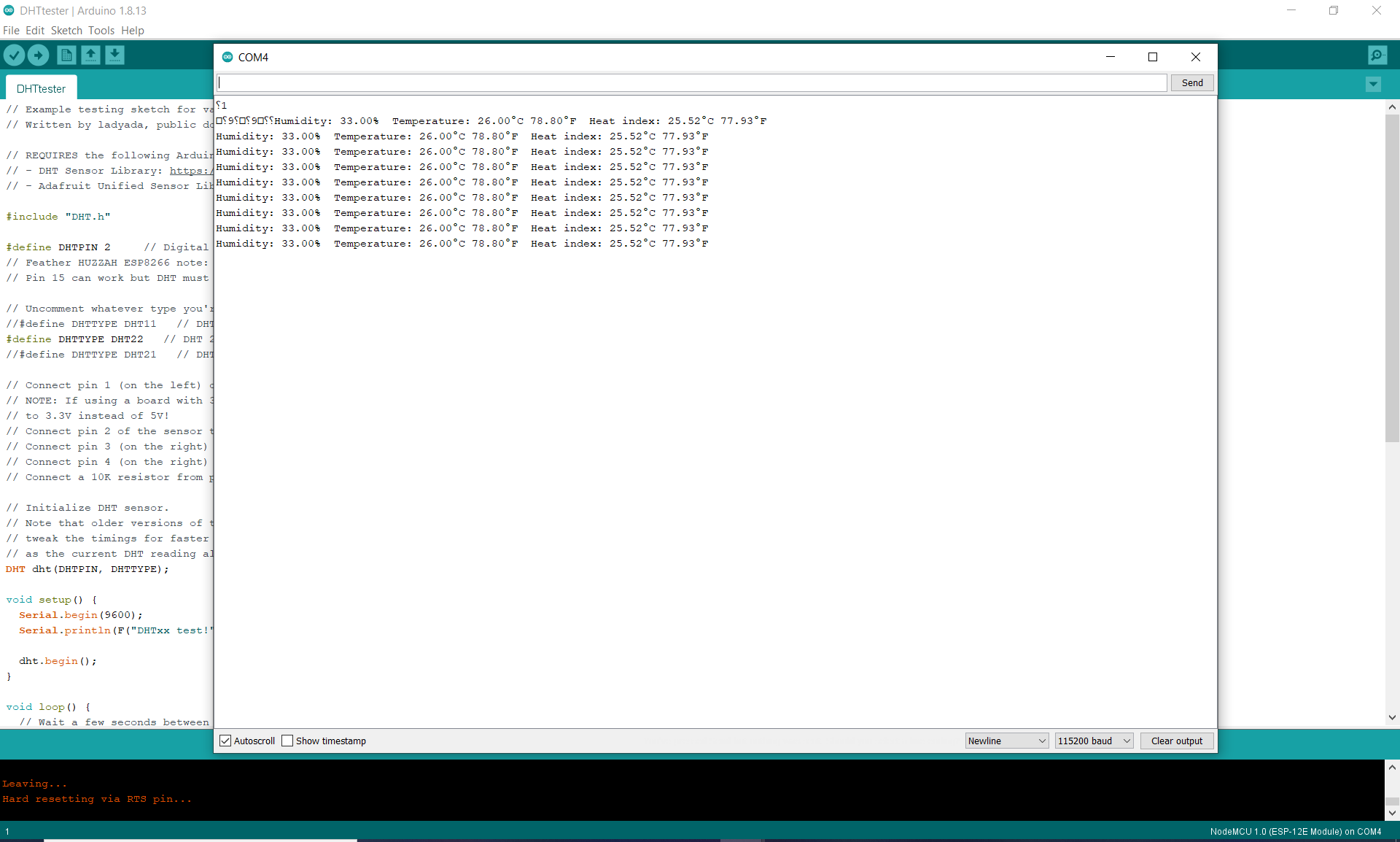
In order to program the board, once again make sure the board is connected and recognized by the computer (check Device Manager), the IDE is open, and then open the DHTtester example from the library you just downloaded. Make sure the correct device (DHT11) and the correct data pin (GPIO 2 of ESP8266 or pin D4 or NodeMCU) are selected.
The program can now be uploaded to the board. To see whether it works, the serial monitor of Arduino IDE can be opened. This program causes the sensor to take new readings every few seconds, and they show up on the serial monitor as follows:
The Arduino file was slightly modified to account for the right pin of the NodeMCU and can be found at the bottom of the page.
As this board was designed in weeks 13-14, a lot more detail can be read there.
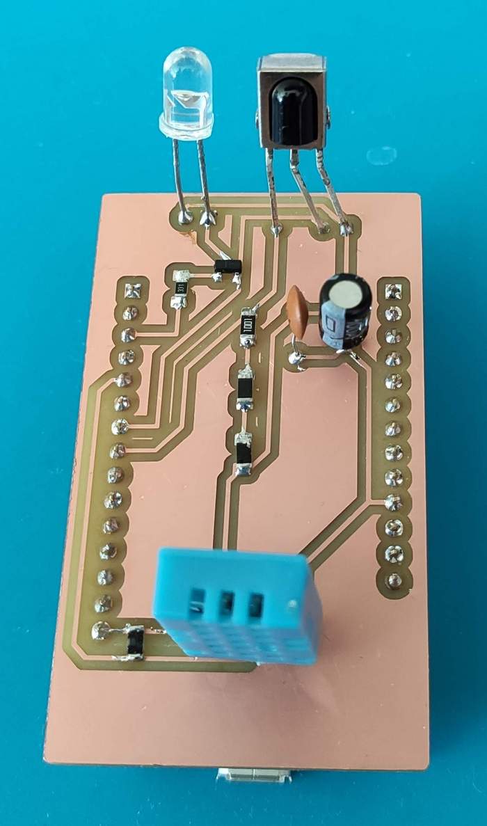
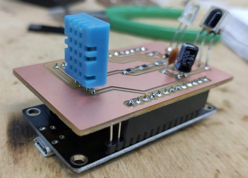
Here is how the final board looked like, with my designed board on one side and the NodeMCU break out board on the other:
Downloading the files
The files for the NodeMCU remote control board can be downloaded here:
- The IR receiver code (.ino, 9 kB -- this is a small modification of Arduino example files)
- The DHT-11 code (.ino, 3 kB -- this is a small modification of Arduino example files)
- The schematic of the board (KiCAD schematic file with .sch extension, 47 kB)
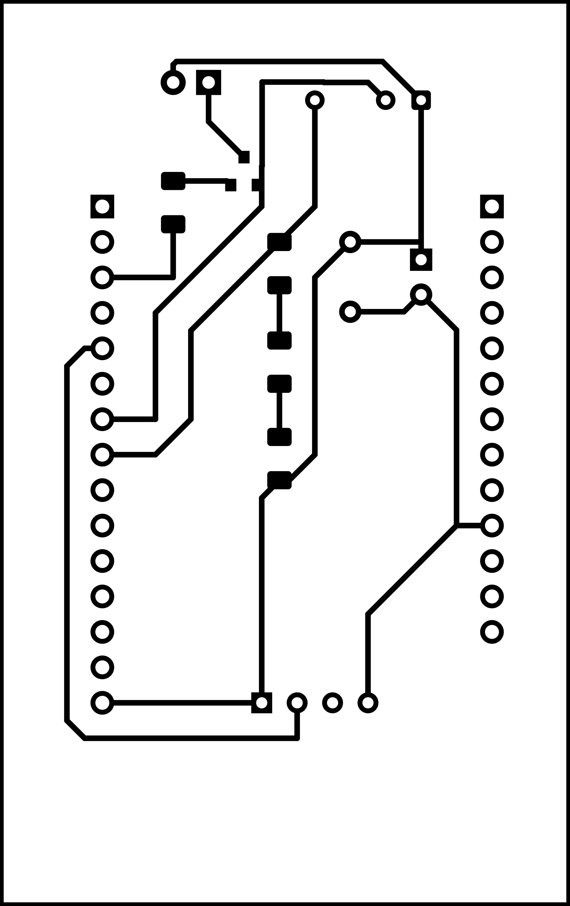
- Monochromatic image of the traces of the board -- should be inverted for milling (.png, 133 kB)
- Monochromatic image of the outline and holes of the board (.png, 72 kB)

Make (almost) anything.


This work is licensed under a Creative Commons Attribution-NonCommercial-ShareAlike 4.0 International License by Maro Aghazarian 2021.