Networking and communications
For this week, we had to try communicating between various nodes either by wire or wirelessly. The key point was that the nodes had to have addresses, so in other words, the network would be expandible.
Here is Dilijan, the land of milk and honey, shining its green eyes at us in the spring, inviting us to leave the lab and venture outside to see nature's fabrication in full swing :)

And here's the bouquet Mariam made with a sample of nature's bounty featuring anmoruk (forget-me-not), never to be forgotten.

Troubleshooting the milling board from last week
Last week I printed the output device board 3 times, every time dealing with the same problem:
The end mill would start milling fine, but then it would get to certain locations and start polishing the copper. I had this problem once before, and it was due to the board being curved and the middle rising after being taped down and clamped. But this time, no curves could be observed visually.
Another reason might be that while pulling up a previously cut board, the board tapes might have been detached in certain places and that could be causing the empty space underneath leading to the copper only being polished while pushed down.
I decided to clean the board thoroughly, remove any trace of tape glue, and even lightly sand it with a P500 sandpaper.
The I washed a previously used board and taped it on, making sure the tapes didn't overlap. Of course this left a small strip in the middle not covered with tape, so I hope this doesn't cause trouble.
Looking back at the troubled board, underneath the polished traces, I could see bumps in the tape, suggesting the tape had just come up, which could be because of lifting force on the board.
I tried with a new board and changed the bit three times, getting the same results each time.
In the end, it appears that the problem was old and worn bits; once Narek used a completely new bit the problem seemed to correct itself.
Using ATtiny45 for SPI bus communication
Serial Peripheral Interface (SPI), also called a four-wire serial bus, is a synchronous serial communication interface specificication used for short-distance comminication, primarily in embedded systems such as liquid crystal displays (LCD's) and secure digital cards. It works by having one master and many secondary nodes.
It is synchronous because the changes in the state of memory elements are synchronized by a clock signal. The four wires of the bus include:
- SCLK: serial clock - this is the clock signal, driven by the master to synchronize the master and secondary;
- SS: secondary select (or CS - chip select) - driven by the master, usually active-low and used to select the secondary node;
- MOSI: Master Out Secondary In - driven by the master, the data for the secondary will appear on this line;
- MISO: Master In Secondary Out - driven by the secondary, where the data from the secondary will go to the master.
The SPI interface was developed by Motorola in the mid-1980s and has become a de facto standard.
Milling the node (secondary) and bridge (master) boards
As mentioned above, the milling wasn't proceeding well until changing the bit to a completely new one. Therefore, the final milled boards I achieved was as follows:
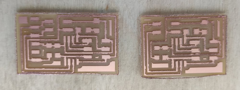
I discovered though that some fine sanding would go a long way in correcting that. I used a P500 sandpaper to gently sand over and around the boards, and even used it to make the sides less sharp and somewhat curved. Here is the result:
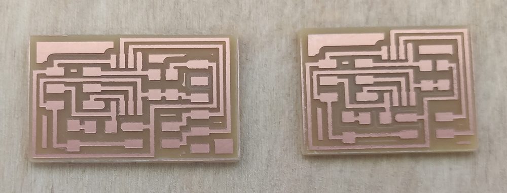
Here's how the boards turned out:
Soldering the components to the boards
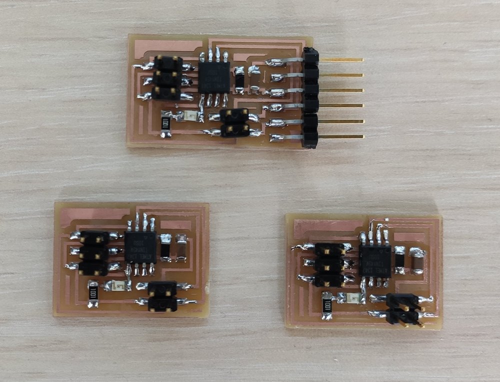
All the components were soldered on:

Here are the final bridge and the two nodes:
Programming the boards to communicate via serial bus
The programming was easy and straight forward, as Neil already had the c code prepared.
What I didn't understand was what the other two python codes (hello.bus.45.bridge and hello.bus.45.node) were for; are these included in the term.py file that we use?
Troubleshooting the programming
After programming the bridge while the ISP and FTDI cables were connected, I disconnected both and connected the FabTinyISP to the ISP of one of the nodes to program it, recompiled the C code to name this node "1", and went on to try and flash the node, but alas, kept getting the following messages:
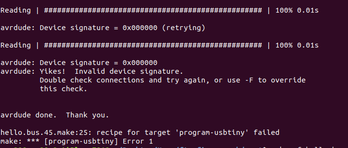
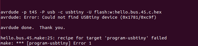
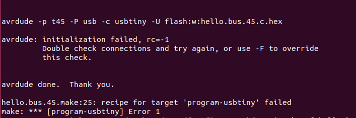
As can be seen, the error message is different every time, but shares the following line at the end:
recipe for target 'program-usbtiny' failed

                         make: *** [program-usbtiny] Error 1
I kept thinking this was due to my FabTinyISP USB connection with the computer, that it wasn't working well, and the board was not receiving power through that. So I kept tinkering with that, and tried plugging in the FabTinyISP directly to the 2.0 USB port of the computer insteading of using a connecting wire (not to accidentally overload the computer motherboard), but alas, it wasn't working. I tried switching the FabTinyISP and it still didn't work.
Finally, I discovered what the problem was: apparently power is not supplied by the FabTinyISP USB connection, and that is why the bridge was also using the FTDI cable to be connected to the computer while being programmed (certainly no serial data was being transmitted through the FTDI cable to the bridge while being programmed).
Since the node does not have a junction for FTDI connection and hence receiving power independently, I connected the node via the 4-wire bus to the bridge, then connected the bridge to the FTDI-to-USB cable with the USB end plugged in to the computer port, and then connected the FabTinyISP to the ISP junction of the node to be programmed:
This time, the programming worked like a charm:
The same process was repeated for the other node as well: the FabTinyISP connected to the node to be programmed, then code compiled with the right identity/address of the node and flashed onto its memory with one command.
Establishing SPI communication between the three boards was a straigh-forward, joyful business per Neil's example.
Home remote with ESP8266 wifi microchip
Since last summer, we have lost our Samsung AC remote control. I wanted to try something with wireless communication, and was wondering if I can replace the remote. My husband, a major tinkerer himself, came up with the idea that I could use the LOLin new NodeMCU v3 with an ESP8255 wifi microchip to not only replace the AC remote control, but also be able to control the TV, the music station, and even our child's toys via wifi using IR LED's connected to the board :)
He suggested using online libraries for the IR codes of the major appliances, and then using an IR receiver to decode other things such as toys which probably wouldn't be in such libraries. Here is one such class specifically dedicated to Samsung AC's I found online. Here's a dedicated IR code database that my husband found.
I could locate and buy IR LED's, but for IR receiver, this is what I found:
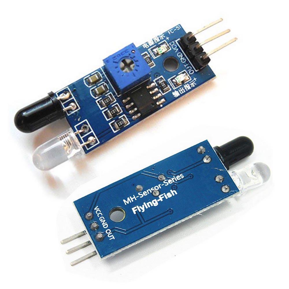
The MH-sensor-series Flying Fish is in fact an IR obstacle and distance sensor with an IR LED and IR receiver mounted on it, so I could perhaps connect to just the receiver without the board components hindering it in some way, which remains to be seen. Let's find out.
ESP8266 The ESP8266 is a low-cost Wi-Fi microchip that allows microcontrollers to connect to a Wi-Fi network and make simple TCP/IP connections. It is made by Espressif Systems[1] in Shanghai, China.
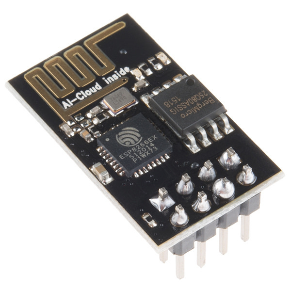
As I mentioned, the board that my husband provided was in fact LOLin new NodeMCU v3, which is an ESP-12E style ESP8266 breakout board which makes it easy to use the ESP8266 microchip: just plug it into a micro USB connector and it is ready.
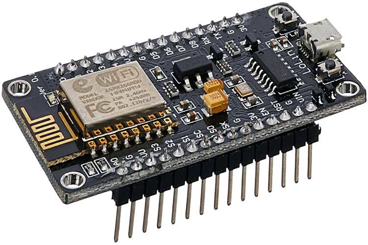
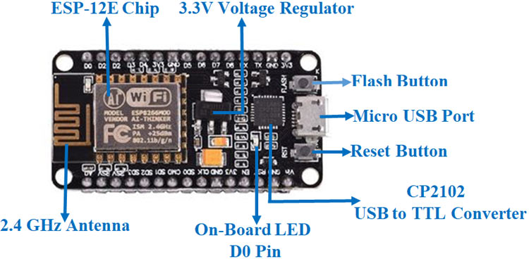
Here are the components on a LOLin new NodeMCU v3: (from here)
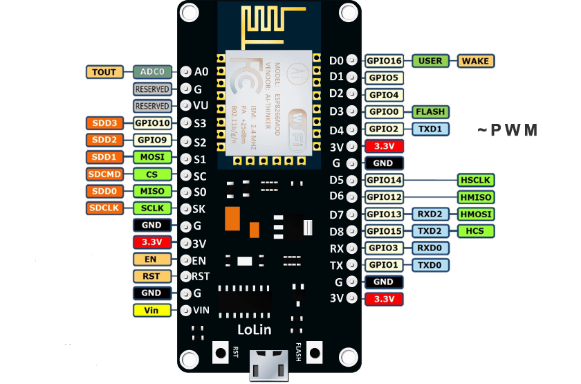
And here are the pin configurations of the breakout board:
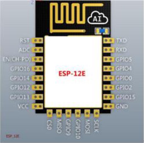
And here is the pin configuration of the ESP_12E, similar to ESP8266 microchip located on the breakout board:
Here is the datasheet for ESP8266.
I decided to give this tutorial a go and see what can be achieved. I also used this tutorial when in doubt.
Here are the steps I followed:
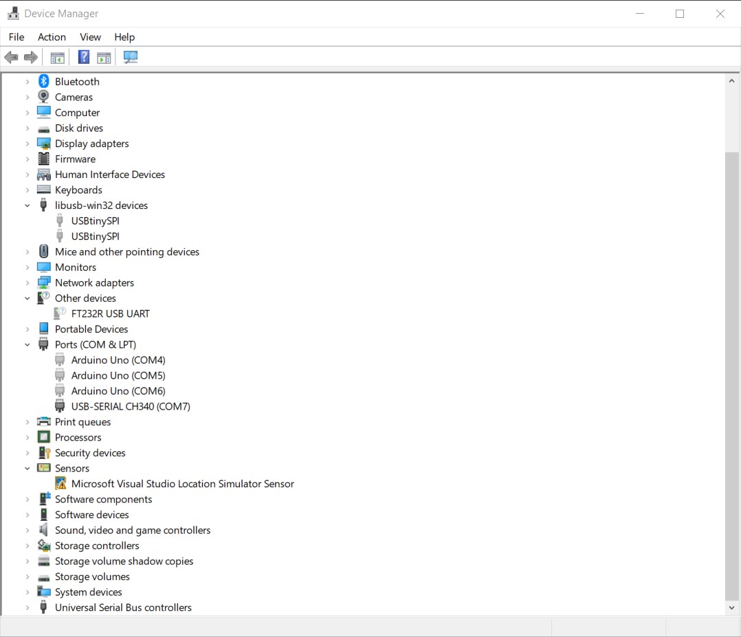
- First, connected the LOLin NodeMCU board to my laptop using a micro USB cable. I tried to see the device
through Device Manager (top open, either right-click on the Windows icon or use
Win+xand select it). Unfortunately, Ports was not showing up in my Device Manager. To activate it, I followed these instructions, and here's what appeared: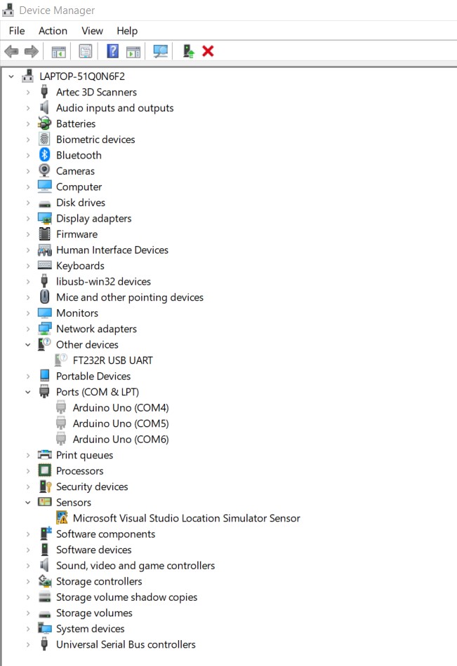
- As the NodeMCU was not showing up, the problem could be one of the following:
- Missing the driver;
- Not geting enough power from the USB, as it needs 400 mA of current. So I tried with the driver. I followed these instructions for installing the NodeMCU driver, with the official drivers downloaded from here.
- Opened the Arduino IDE. Clicked on
Toolson Arduino toolbar. Clicked onBoardand selectedBoard Manager, searched for ESP8266 and installed it. - Then went to
Sketchfrom in the toolbar and selectedInclude Library, thenManage Libraries.... Then searched forIRremoteESP8266and installed it. - Cliked on
Toolsfrom the toolbar, went toBoards, selectedNodeMcu 1.0 (ESP-12E Module). - At this stage, I could setup an IR receiver to decode IR data from various remote controls. I could not find and IR receiver in the store, instead, I got an FC-51 IR obstacle and distance sensor. This had an IR receiver on it that I thought I might use. However, it turned out this one was a 2-pin receiver and I needed a 3-pin IR receiver. Here the difference between a 2-pin and 3-pin sensor was explained by johnwasser: "A 2-pin sensor is usually a photodiode or phototransistor. It conducts when it gets hit with any IR energy. A 3-pin sensor usually has a digital output (on or off) and reacts to modulated IR only, typically 36 to 40 kHz modulation frequency as used by most IR remote controls. If you want to receive IR remote signals, use the 3-pin models. If you want to measure IR intensity use the 2-pin models." Since I had a library for some of the IR codes I needed, I could skip this step until I can get a 3-pin IR receiver.
- Now the IR LED would have to be connected to NodeMCU. However, that is not possible since the NodeMCU can't deliver enough current.
In order to solve this issue, the IR LED would have to be connected to NodeMCU through a transistor such as
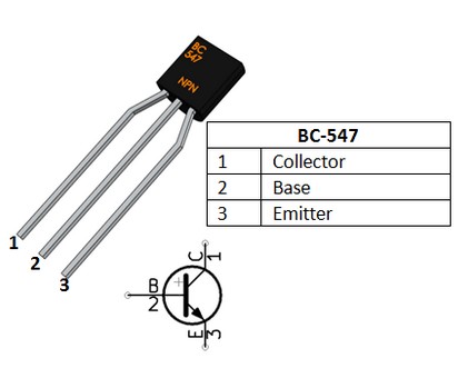
2N222 (600 mA), 2N3904 (600 mA), or BC547 (100 mA). Of these, I had the
BC547 NPN through-hole transistor, and
BC847 NPN smd transistor (100 mA). Decided
to use BC547 with a breadboard to see whether it works before designing a PCB. Here's the pin
configuration of BC547:
This is how they should be connected: (photo credit: the Instructibles tutorial)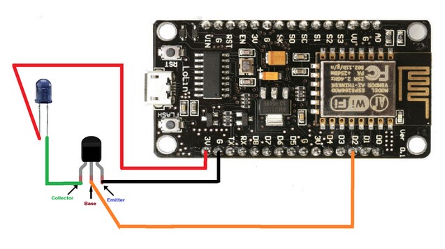
And this is how it turned out: - I coded it using
File -> Examples -> IRRemoteESP8266 -> ControlSamsungAC, and since it was hard to keep looking at it with a phone to see the IR LED turn on or off, I switched it to a regular LED to see whether it was functioning. It turned out fine, though I'm not sure the power is just enough. - Later I tested it with a 330 Ω resistor between the base and pin D2, which seems to have increased the brightness of the LED.
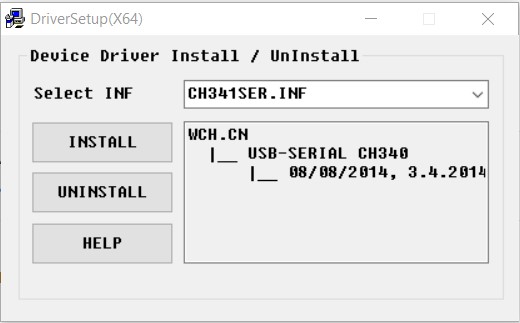

According to the installer's help, if the driver were connected, after installing the driver, it should have immediately recognized the board. However, there was not even a sign of the board's presence in Device Manager. So I thought it must be the power. Tried hooking up with board with the power supply and cranked it up all the way to 13 V. Still nothing.The problem was, Windows was not making any sound when plugging in the board or showing it in any way in Device Manager, as if the board didn't exist.I spend half a day unsuccessfully trying to figure out what was wrong. At the end, I tried this forum, where everybody else seemed to have the same problem, and sschoker suggested changing the cable. So I tried another micro USB and lo and belhold! Not only Windows made a 'plug-in' noise and Device Manager detected something, it detected the right thing with the driver installed:
Trying ESP8266 as a wifi access point
Tried File -> Examples -> ESP8266WiFi -> WiFiAccessPoint. Neil also has a similar video
here.
Trying ESP8266 as an IR server
Tried File -> Examples -> IRRemoteESP8266 -> IRServer. Neil also has a similar video
here.
Other interesting endeavors
FTDI cable
Getting to the assignment on networking, I think it's high time I'd made my own FTDI :) But since we were missing 470 Ω resistors, will give it a go another week.
How to read numbers on SMD resistors
A bit late in the course, but this week I discovered what the numbers printed on an SMD resistor mean, and here is a wonderful website that helped in the process.
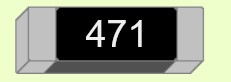
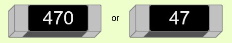
Each SMD resistor typically comes with a 3-digit number printed on it. The first two numbers are the first two digits of its resistance, and the last (third) digit specifies how many zeroes follow the first two digit if the resistance is expressed in Ohms. So this is 470 Ω:
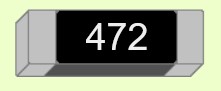
This is 4700 Ω or 4.7 kΩ:
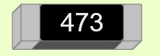
This is 47000 Ω or 47 kΩ:
And 47 Ω itself can be expressed as either of the following ways:
Downloading the files
The files for the NodeMCU remote control board can be downloaded here:
- The schematic of the board (KiCAD schematic file with .sch extension, 47 kB)
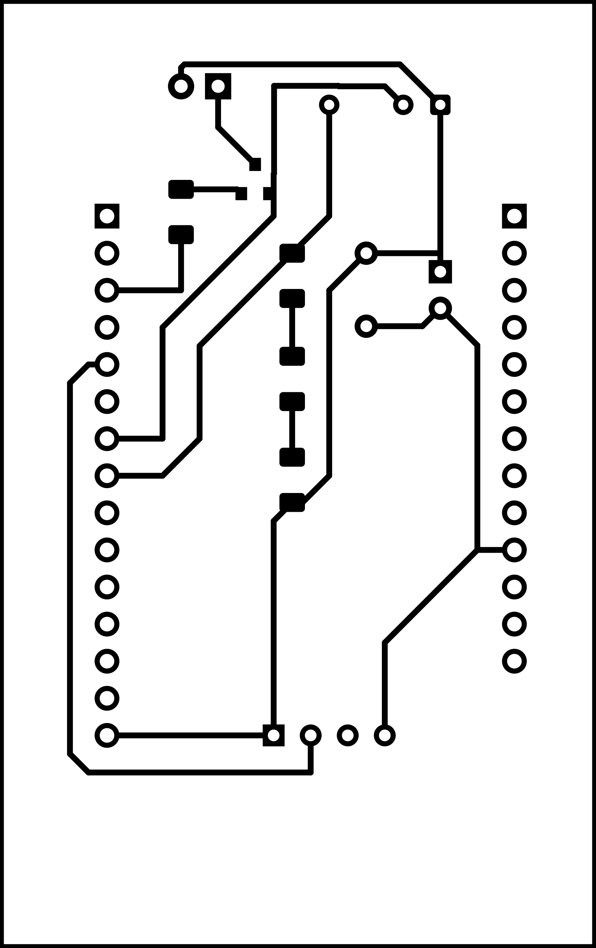
- Monochromatic image of the traces of the board -- should be inverted for milling (.png, 133 kB)
- Monochromatic image of the outline and holes of the board (.png, 72 kB)


