How to make (almost) anything.
Week 12. Output devices
Work done in the Lab under the guidance of my remote Instructor to accomplish the weekly assignments.
After a year in quarantine, the activities at the university where I work are almost normalized, so this week I did not have much time to work on my assignment, I tried to keep it as simple as possible complementing something that I have already worked on in previous weeks.
Group assignment
For this Group assignment we measured the power consumption of an output device, you can read it there.
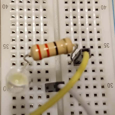
We measured the power consumption of the super bright white LED that is in my Arduino circuit next to a resistor.
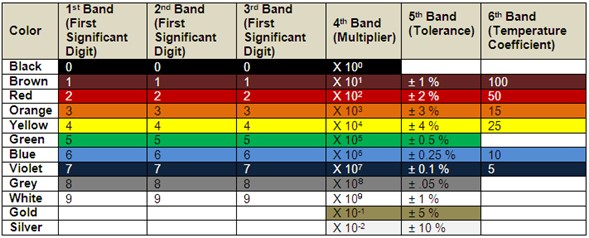
The resistor has four colored bands (red, red, black and gold) that identify it with 220 Ohms.
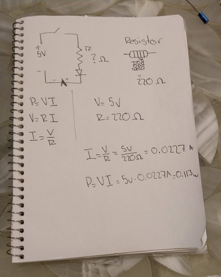
To calculate the consumption of the circuit, we first calculate the current using the two values we knew: the voltage (5v) and the resistance (220 Ohms), resulting in 0.227 A.
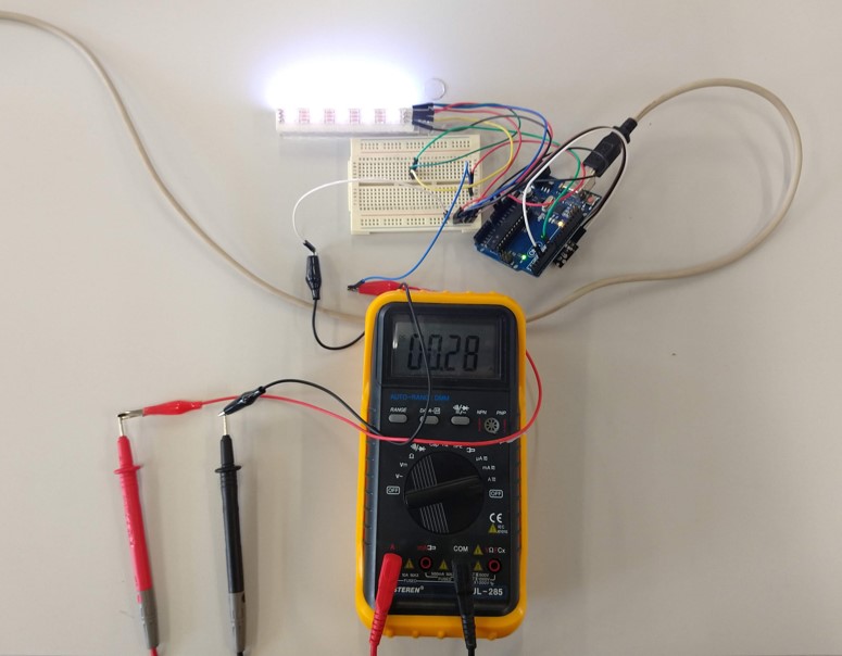
To verify this value we have used the multimeter in the current position in mA and connected the terminals to the negative pole of the LED and to the GND of the Arduino board. It displayed almost the same value.
Finally we calculate the power consumption by multiplying the current by the voltage, resulting in 0.113 watts.
For my final project I am using WS2812 LEDs (also known as Neopixels), which according to the manufacturer consume an average of 20 mA, and up to 60 mA when used at maximum brightness. I wanted to know the consumption of my LEDs using my own code, and once again I used the multimeter to verify this data. With 10 LEDs connected it showed a value of 280 mA, so the average manufacturer specification is not so wrong: the individual consumption of the LEDs at the brightness level that I am using is 28 mA.
LED as output device
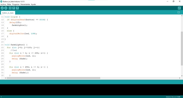
For my final project I'm starting to work on programming, so this week I experimented with new code options to interact with the pushbutton (input device) and the LED (output device): pressing the button performs a Fade sequence on the LED that represents inhalation and exhalation as you breathe.
Code
    int led = 11;
int button = 8;
const int fade = 10;

void setup() {
  pinMode(led, OUTPUT);
  pinMode(button, INPUT);
  digitalWrite(led, LOW);
}

void loop() {
  if (digitalRead(button) == HIGH) {
    delay(15);
    fadeLights();
  } else {
    digitalWrite(led, LOW);
  }
}

void fadeLights() {
  for (int j = 0; j <=5; j++){
    //led
    for (int i = 0; i <= 255; i++) {
      analogWrite(led, i);
      delay (fade);
    }
    {
      delay (3000);
    }
    for (int i = 255; i >= 0; i--) {
      analogWrite(led, i);
      delay (fade);
    }
    {
      delay (3000);}
  }
}
Neopixels as output devices
For my second test I wanted to increase the level of complexity so I decided to work with the neopixels that I will use in my final project, as well as the board that I am developing, in this way I can make a diagnosis of what is failing and the improvements that I can do in the next version.
|
Neopixels (WS2812 leds)
|
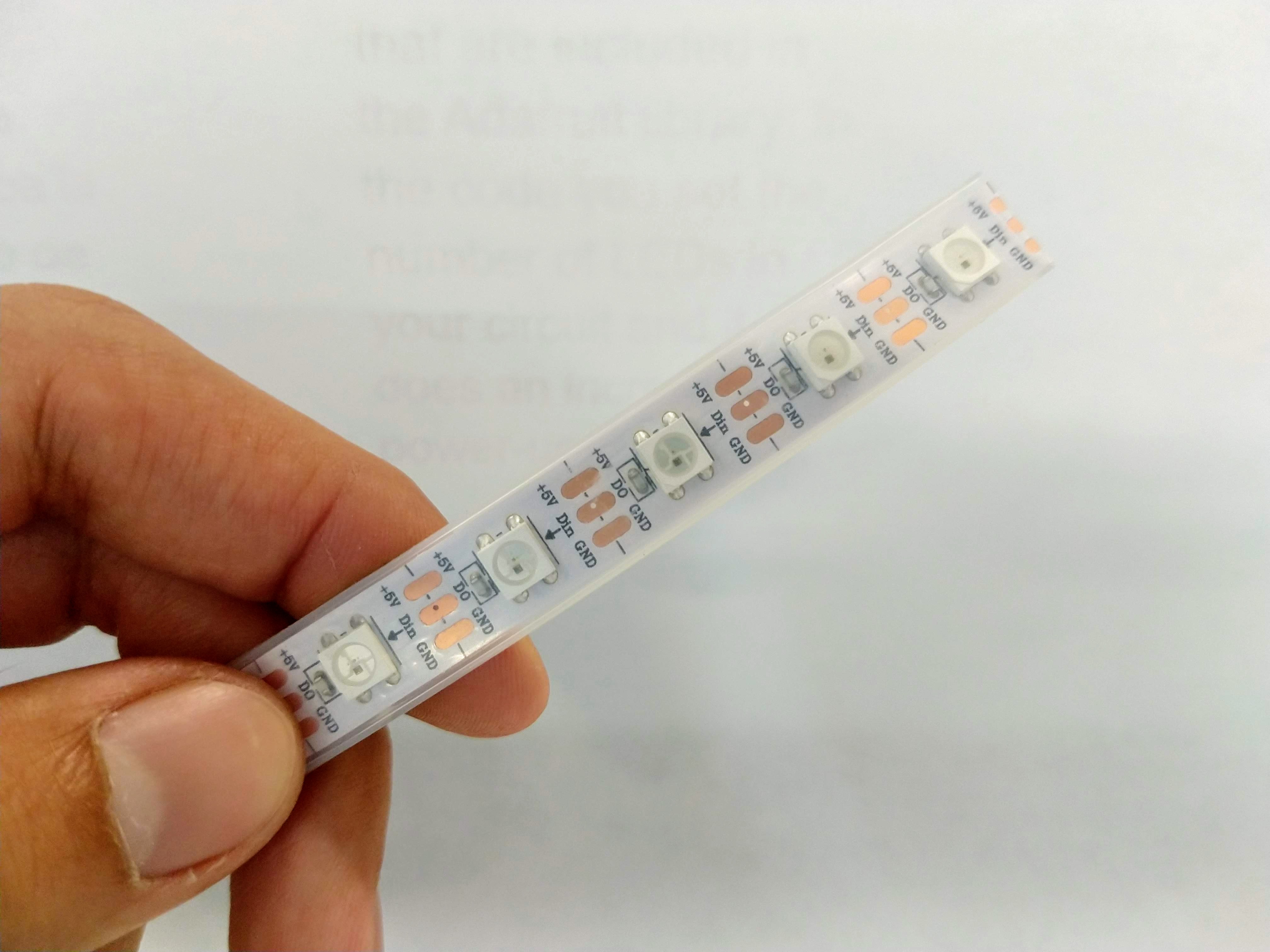
I started by cutting the neopixel strip to use only five LEDs, these are powered by 5v, and have three pins: VCC, GND and DataInput. I connected these to my board using the Arduino Pin #6 and the VCC and GND outputs directly (my board is connected to a 5v 2A AC/DC adaptor so it can handle them). I did the first test with one of the example codes that are included in the Adafruit library.
Code
    // NeoPixel Ring simple sketch (c) 2013 Shae Erisson
// Released under the GPLv3 license to match the rest of the
// Adafruit NeoPixel library

#include <Adafruit_NeoPixel.h>
#ifdef __AVR__
 #include <avr/power.h> // Required for 16 MHz Adafruit Trinket
#endif

// Which pin on the Arduino is connected to the NeoPixels?
#define PIN        6 // On Trinket or Gemma, suggest changing this to 1

// How many NeoPixels are attached to the Arduino?
#define NUMPIXELS 5 // Popular NeoPixel ring size

// When setting up the NeoPixel library, we tell it how many pixels,
// and which pin to use to send signals. Note that for older NeoPixel
// strips you might need to change the third parameter -- see the
// strandtest example for more information on possible values.
Adafruit_NeoPixel pixels(NUMPIXELS, PIN, NEO_GRB + NEO_KHZ800);

#define DELAYVAL 500 // Time (in milliseconds) to pause between pixels

void setup() {
  // These lines are specifically to support the Adafruit Trinket 5V 16 MHz.
  // Any other board, you can remove this part (but no harm leaving it):
#if defined(__AVR_ATtiny85__) && (F_CPU == 16000000)
  clock_prescale_set(clock_div_1);
#endif
  // END of Trinket-specific code.

  pixels.begin(); // INITIALIZE NeoPixel strip object (REQUIRED)
}

void loop() {
  pixels.clear(); // Set all pixel colors to 'off'

  // The first NeoPixel in a strand is #0, second is 1, all the way up
  // to the count of pixels minus one.
  for(int i=0; i<NUMPIXELS; i++) { // For each pixel...

    // pixels.Color() takes RGB values, from 0,0,0 up to 255,255,255
    // Here we're using a moderately bright green color:
    pixels.setPixelColor(i, pixels.Color(0, 150, 0));

    pixels.show();   // Send the updated pixel colors to the hardware.

    delay(DELAYVAL); // Pause before next pass through loop
  }
}
Then I did another test with the Neopixels for a color change from orange to red that will work as a visual indicator to inhale or exhale. For this one i used two strips connected to the same output pin.
The code lights the LEDs one by one in orange and when the whole strip lights up, the pixels change color to red in the reverse direction.
Code
#include <Adafruit_NeoPixel.h> //Neopixel library
#define PIXEL_PIN    6    // Digital IO pin connected to the NeoPixels.
#define PIXEL_COUNT  5    // Number of pixels

Adafruit_NeoPixel strip = Adafruit_NeoPixel(PIXEL_COUNT, PIXEL_PIN, NEO_GRB + NEO_KHZ800);

void setup() {
  // Setup code, to run once:
  strip.begin();          //Start the strip operation
  strip.show();           //Initialize all pixels to OFf
  }

void loop() {
  // Main code, to run repeatedly:
  strip.setBrightness(50); //Global brightness for the strip
  for(int i = 0; i < 5; i++){  //Increase in the number of illuminated pixels with this color
    strip.setPixelColor(i, 252, 102, 3); //Blue position on RGB values
    strip.show(); //Turn on the pixels
    delay(1500); //Delay
  }
  for(int i = 4; i >= 0; i--){  //Decrease in the number of illuminated pixels with this color
    strip.setPixelColor(i, 252, 3, 3); //Red position on RGB values
    strip.show(); //Turn on the pixels
    delay(1000); //Delay
  }
 }
After this test I am considering using a gradual Fade of all pixels instead of this pixel by pixel increment, I think it will light more and the user experience will be better by avoiding distractions.
Problems I faced
The problem I had at the beginning of this assignment was that my four LED strips did not turn on at the same time, I solved this by calculating the consumption of each LED and having this information I reduced the number of LEDs in my circuit considering that I am going to use a source of power of 5v 2A, ending with just 20 LEDs. Luis told me that I should measure BEFORE connecting so many LEDs since it could have burned the processor due to the current withdrawal.
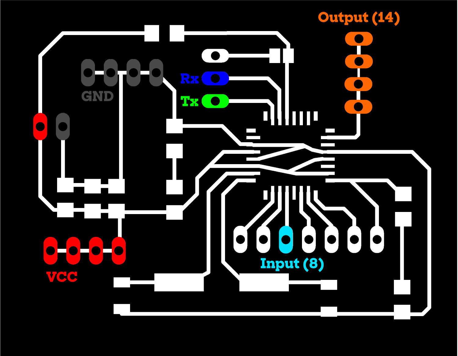
The other problem I faced is that on my board I have spare connections for Inputs and Outputs, but not enough VCC and GND pins: I only have four pairs to power the four LED strips (output) and I don't have another one to power the button (input). I solved this for now using a breadboard but I need to correct this on my board to make it 100% functional in my final project.
Files
You can download the .INO files here: Single LED,Neopixel.
You can download the board files here: schematic, board.
|
For this assignment I:
|