How to make (almost) anything.
Week 10. Input devices
Work done in the Lab under the guidance of my remote Instructor to accomplish the weekly assignments.
This week I made a few tests with buttons on Arduino.
Group assignment
For this Group assignment we probed an input device's analog levels and digital signals. You can read it there.
On this topic I had no idea where to start so I decided to dedicate my assignment to my final project. I need to make a code that identifies a button press that triggers a Fade sequence on an LED (roughly this is what my final project, a Guided breathing lamp, will do: perform a light sequence after pressing a button). Possibly I should do this on my own PCB but it is literally my first time doing programming and electronics so I will start my testing with the simplest, Arduino and a breadboard. Sorry Neil, I'll add the components to my PCB later and program it, it's taking a lot of work to catch up with so much information.
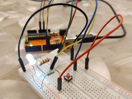
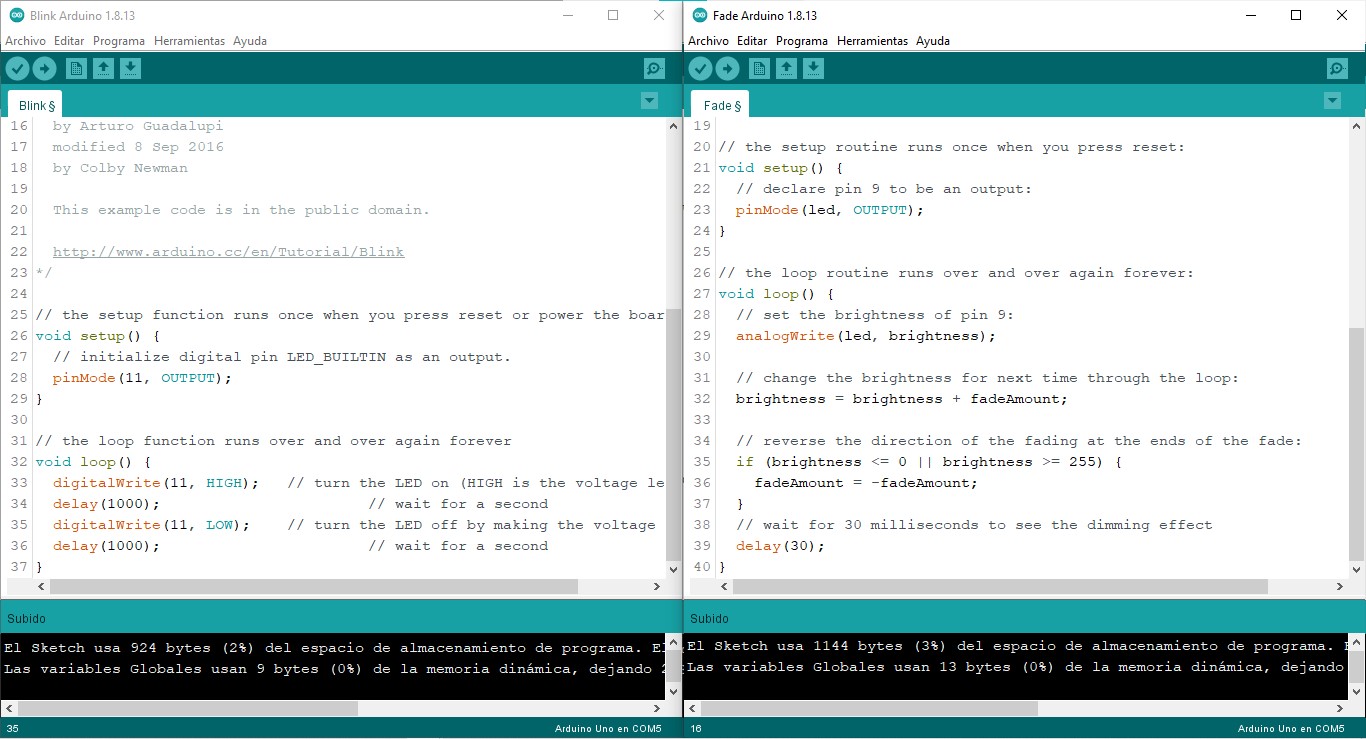
I started by testing the sample codes that are preloaded in the Arduino IDE, codes like Blink and Fade, to make sure I understood the basic structure of the code as well as the placement of the circuit elements.
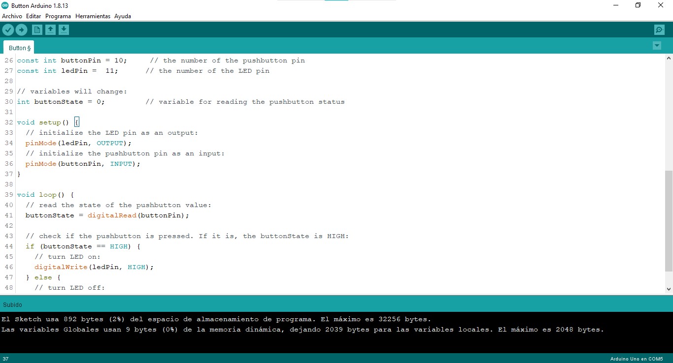
These basic codes worked fine and I just had to follow the instructions, I was hoping the rest of the work would be that easy. I looked on the Arduino page for a code to incorporate a button to the circuit, and making the necessary connections the code worked perfectly (you have to be careful to connect the pins correctly and not omit the resistors as this may cause unstable operation of the LED). The code is very similar to the one that comes as an example in the software but here they explain in depth different modifications in the circuit.
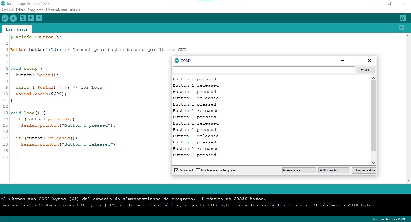
To fulfill the assignment I looked for another code that would monitor the button press and display the legend BUTTON PRESSED and BUTTON RELEASED on the serial monitor. In this case I found a whole library that corrects certain erratic behaviors in the buttons (which I personally did not notice but it is still good to have a reference on "debouncing"), it is incredible all the work that you can economize using libraries and publicly shared codes.
Everything worked, so it was time to increase the difficulty: the LED must remain lit even when the button is released, this implies creating a new WRITE function within the button function so that the action of this is preserved even after of another change of state. Here the problems began, I could not assimilate how to make a fixed function, but my friend Paul McWhorter helped me with his tutorial (and also explained the problem with the lack of resistors).
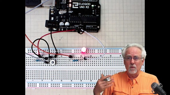
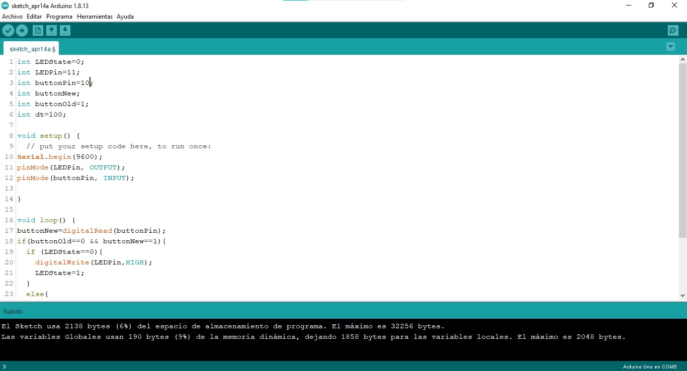
Once the LED stayed lit even after releasing the button the logical step was to complement this code with the Fade code so that everything works together: press the button to start the Fade sequence automatically, and press it again to turn off the LED. I failed but I still liked the result.
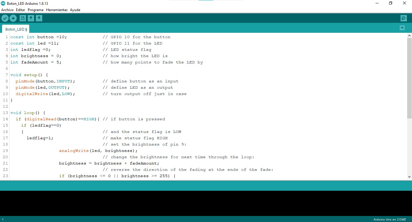
My problem was the logic in the program, I needed to indicate a switch between different functions each time the button was pressed, but in the code I was just indicating that the function changed depending on the state of the button (pressed = function 1, not pressed = function 2). I solved it by researching about switchcase, which basically allows you to establish different scenarios, each one with functions to perform and specific conditions under which they are executed.
Understanding this was fundamental for me as the code for my final project is based on multiple cases, considering that my device will have different functions and the change between them will depend on a single button.
Final project update: push button
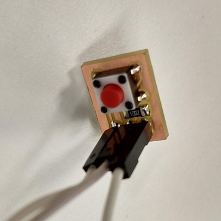
For my final project I made a board with a button that controls the operations of the lamp, which uses a pushbutton, a 10K resistor and three headers (current, ground and signal).
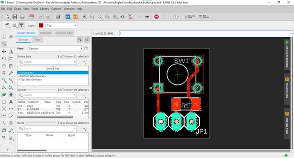
In the lab we had buttons for surface mount and through hole, I would have preferred to use the surface mount ones since they are smaller and the color would not be visible inside the lamp, but the feedback when pressing it was practically imperceptible so at least for now I used a through hole one.
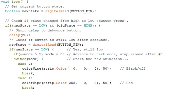
The programming for this test was an evolution of the previous code that turns the LED on and off, for my project I need a reading of the button state change (high to low or vice versa) and that change detonate a switch case. The example code "buttoncycler" from the Adafruit library for Neopixel was very useful to me.
The test run with my own board was successfull. I still have to research how to interrupt a sequence of the neopixels before it ends, but at the moment I am satisfied with this.
Final project update: capacitive sensor
Considering an improvement for the user experience on my project I tried Neil's recommendation about making my own capacitive sensors, which are proximity sensing devices that can detect a user's finger, for example, without the need for physical contact.
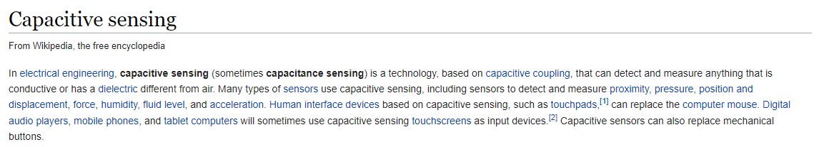
A capacitive sensor acts like a simple capacitor: a metal plate in the sensing face of the sensor is electrically connected to an internal oscillator circuit and the target to be sensed acts as the second plate of the capacitor. On this case I put a 1M ohm resistor between two pins on an Arduino board and connected one of the pins to a copper plate that served as a terminal.
In the serial plotter my touch was correctly identified, so I made another test with an LED changing its behavior according to the reading of the sensor that is printed on the serial monitor: when the value is higher than 1,000 ohms the LED blinks (this value can be modified on the code but changes according to the resistor capacity).
And finally I incorporated the sensor into the code of my device: by gently touching the copper it switches between the different functions of the neopixels.
    /*  Breathonome
 *  Cycle NeoPixels with capacitive sensor, includes sleep function.
 *  ATmega328P
 *  Jonathan León
 *  2022-13-06
 *  Thanks to surveyranger, Paul Stoffregen and Konstantin Dimitrov for their sample codes that made this release possible.
 *
 *  A copper plate acting as a capacitive sensor is connected to a 1 megohm resistor between
 *  pins 7 and 8 cycles through different modes (cases). Mode stops and switches to the
 *  next mode when the sensor detects a touch.  Current mode plays until button is pressed or
 *  goes into sleep mode after 20 minutes.
 *  Capacitive sensor is connected to the resistor leg on pin 8.
 *  NeoPixel data in connected in series with a 330 ohm resistor to pin 14.
 */


#include <CapacitiveSensor.h>

#include <Adafruit_NeoPixel.h>

#define PIXEL_PIN    14    // Digital IO pin connected to the NeoPixels.

#define PIXEL_COUNT  5

Adafruit_NeoPixel strip = Adafruit_NeoPixel(PIXEL_COUNT, PIXEL_PIN, NEO_GRB + NEO_KHZ800);

CapacitiveSensor   cs_7_8 = CapacitiveSensor(7,8); // 1M resistor between pins 7 & 8, pin 8 is sensor pin, add a wire and or foil

unsigned long idleMillis;            // Measure idle time between button presses
unsigned long patternInterval = 20 ; // time between steps in the pattern
unsigned long lastUpdate = 0;        // for millis() when last update occurred
unsigned long showSpeed [] = { 600, 600, 600 } ; // speed for each pattern - add here when adding more cases ****************************
int fadeStep = 0;                    // state variable for fade function

////////const byte BUTTON_PIN = 6;           // Pin 6 / PCINT0 / externalInterrupt / REPLACED BY CAPACITIVE SENSOR


void setup()
{
   cs_7_8.set_CS_AutocaL_Millis(0xFFFFFFFF);// turn off autocalibrate on channel 1 - just as an example
   Serial.begin(9600);
   ////////pinMode(13,OUTPUT);    / LED DEBUGGING, REPLACED BY NEOPIXELS

  pinMode(PIXEL_PIN, OUTPUT);
  ////////pinMode(BUTTON_PIN, INPUT);
  ////////digitalWrite(BUTTON_PIN, HIGH);    // Activate pull-up resistor to set pin HIGH

  strip.begin();
  strip.show();             // Initialize all pixels to 'off'
  wipe();                   // Clear buffers on pixels
  idleMillis = millis();    // Start idle time
}

void loop()
{

  short stage = 0;


 long sensor1 =  cs_7_8.capacitiveSensor(50);


   Serial.println(sensor1);  // print sensor output

   if(sensor1 >= 1000)
   {
    stage = 1;
   }
   else{
    stage = 0;
   }


static byte idleTime = 20;  // Sets idle time (in minutes) before sleep mode ******************************
  if (millis() - idleMillis >= (1000UL*60*idleTime))   // 1000(unsigned long)ms * 60(sec/min) * # minutes
  {
    strip.clear();
    colorWipe(strip.Color(  0,   0,   0), 50);
  }

  // Start with case 0
  static byte showType = 0;
  static bool oldState;

  // Get current button state
  bool newState = stage;

  // Check if state changed from high to low (button press)
  if (newState == 1 && oldState == 0)
  {
    showType++;                // Move to next showType
    fadeStep = 0;              // Reset fade state variable
    idleMillis = millis();     // Reset idle timer
    if (showType > 2)          // If showType exceeds number of shows
    {
    showType = 0;              // Reset showType to case 0
    }
    patternInterval = showSpeed[showType];  // Set speed for this pattern
    //colorWipe(strip.Color(  0,   0,   0), 50);                    // Clear out pixel buffer
    delay(20);                 // Debounce delay
  }
  oldState = newState;         // Update state
  if (millis() - lastUpdate > patternInterval)
  {
    startShow(showType);
  }


}


void startShow(int showPattern)
{
  switch(showPattern)
  {
    case 0: colorWipe(strip.Color(  0,   0,   0), 50);    // Black/off
            break;
    case 1: fade(0, 1, 0, 255, 0, 255, 600);              // Fade from black to blue and back
            break;
    case 2: colorWipe(strip.Color(  255,   255,   255), 50);    // White
            break;
  }
}

// clear all LEDs
void wipe()
{
  for(byte i=0;i<strip.numPixels();i++)
  {
    strip.setPixelColor(i, strip.Color(0,0,0));
    strip.show();
  }
}


// Fill strip pixels one after another with a color. Strip is NOT cleared
// first; anything there will be covered pixel by pixel. Pass in color
// (as a single 'packed' 32-bit value, which you can get by calling
// strip.Color(red, green, blue) as shown in the loop() function above),
// and a delay time (in milliseconds) between pixels.
void colorWipe(uint32_t color, int wait) {
  for(int i=0; i<strip.numPixels(); i++) { // For each pixel in strip...
    strip.setPixelColor(i, color);         //  Set pixel's color (in RAM)
    strip.show();                          //  Update strip to match
//    delay(wait);                           //  Pause for a moment
  }

    // time for next change to the display
  lastUpdate = millis();
}


void fade(byte redStartValue, byte redEndValue, byte greenStartValue, byte greenEndValue, byte blueStartValue, byte blueEndValue, int totalSteps)
{
  static float redIncrement, greenIncrement, blueIncrement;
  static float red, green, blue;
  static bool fadeUp = false;

  if (fadeStep == 0) // first step is to initialise the initial colour and increments
  {
    red = redStartValue;
    green = greenStartValue;
    blue = blueStartValue;
    fadeUp = false;

    redIncrement = (float)(redEndValue - redStartValue) / (float)totalSteps;
    greenIncrement = (float)(greenEndValue - greenStartValue) / (float)totalSteps;
    blueIncrement = (float)(blueEndValue - blueStartValue) / (float)totalSteps;
    fadeStep = 1; // next time the function is called start the fade
  }
  else  // all other steps make a new colour and display it
  {
    // make new colour
    red += redIncrement;
    green +=  greenIncrement;
    blue += blueIncrement;

    // set up the pixel buffer
    for (byte i = 0; i < strip.numPixels(); i++)
    {
    strip.setPixelColor(i, strip.Color((byte)red,(byte)green,(byte)blue));
    }

    // now display it
 //   strip.setBrightness(50);  // dim output to conserve battery
    strip.show();

    // go on to next step
    fadeStep += 1;

    // finished fade
    if(fadeStep >= totalSteps)
    {
      if(fadeUp) // finished fade up and back
      {
        fadeStep = 0;
        return; // so next call recalabrates the increments
      }

      // now fade back
      fadeUp = true;
      redIncrement = -redIncrement;
      greenIncrement = -greenIncrement;
      blueIncrement = -blueIncrement;
      fadeStep = 1; // don't calculate the increments again but start at first change
    }
  }
}
Files
You can download the codes here: Single LED fade, Button switching cases, Neopixel mode change using button, Capacitive sensor as LED trigger.
You can download the Eagle files for the button board here: scheme, board.
|
For this assignment I:
|