How to make (almost) anything.
Week 9. Mechanical design, machine design
Work done in the Lab under the guidance of my remote Instructor to accomplish the weekly assignments.
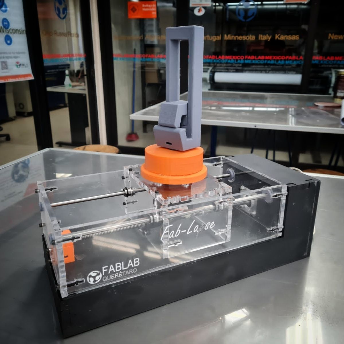
This week we made a machine: a timelapse rail for smartphones.
Take a look at the group assignment page.
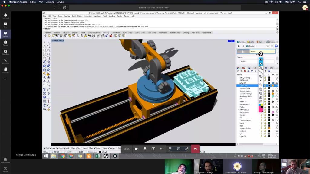
Because we are taking FabAcademy remotely, we connected via Zoom and Teams to organize the work, in this way we were able to collaborate between Querétaro, Puebla and México (each one from our local laboratory and Iván as instructor from México City).

In Querétaro we build the first stage of the FabLapse that includes the chassis, the two stepper motors (one for the 360° turn and the other for the linear movement) and the smartphone stand. The chassis is made of acrylic to support the movement of the entire system and its assemblies are screwed to prevent it from falling apart due to vibrations.
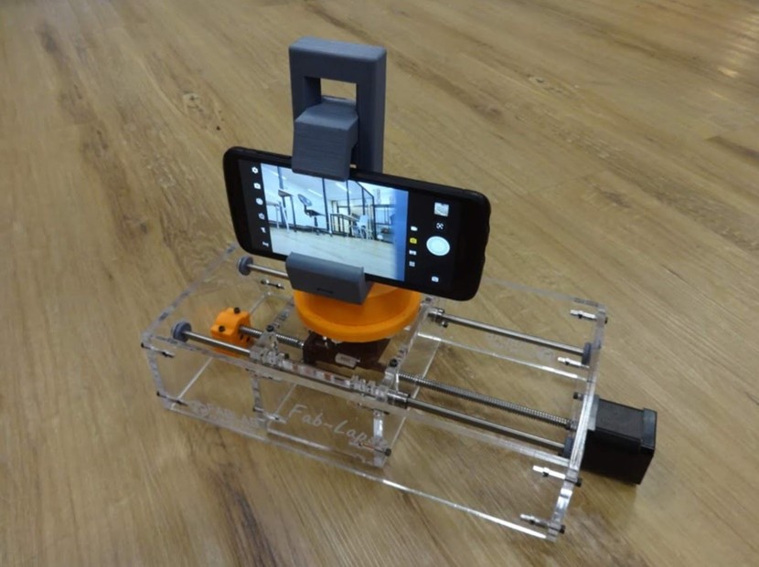
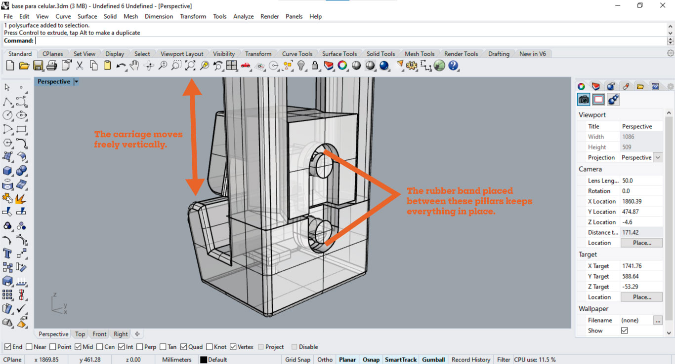
My main contribution to this project was the adjustable cell phone base, which is compatible with cell phones of different shapes and sizes, and is useful not only with our project but also with any traditional tripod because it has the space for a 1/4" nut.
Our biggest concern was to have the correct fastening of the phone to the base during movement, so the simplest solution was to integrate two pivots to place a rubber band to keep the cell phone in the proper position.
To help with the mechanical design I did some research on the motors that I'm going to share here.
Due to the shortage derived from the pandemic, obtaining electronic components was complicated since many distributors did not have stock and delivery times were very slow. Having little time to get components and going through the Easter holidays (during which we do not have access to the laboratory at least in Querétaro) made us make the decision to adapt to what we had available in inventory, and fortunately we had a couple stepper motors, one with D-Shaft and one with a 300mm Lead-Screw. We wish we had at least a 500mm threaded rod for fuller travel but this was better than nothing.
These are the data sheets:
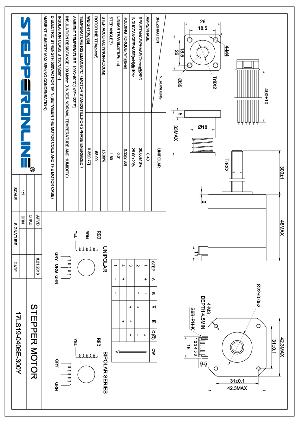
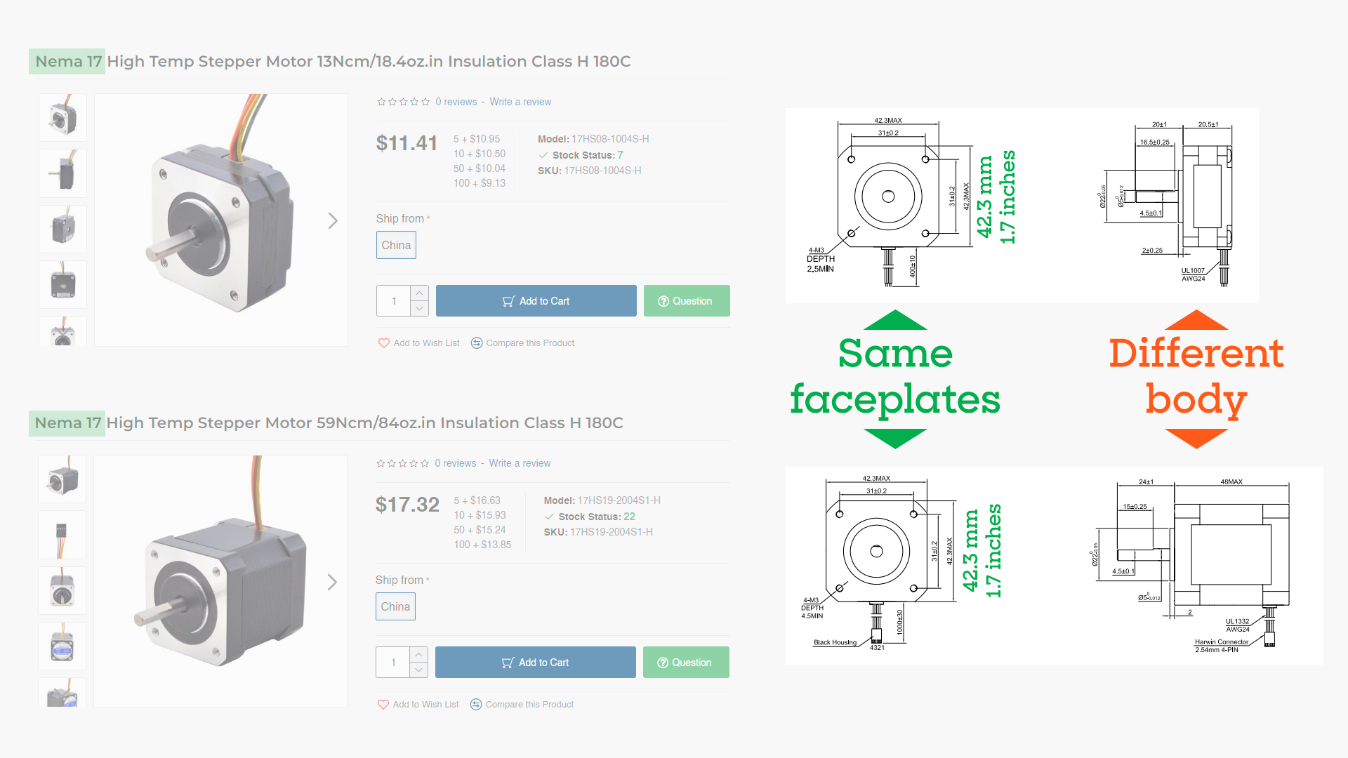
Nema 17 linear stepper motor with Anti-backlash screw nut, the motor part is 12V 0.4A 48mm 1.8 degree 6 wires Nema 17 stepper motor. Integrated with 300mm Tr8x2 threaded rod and a Anti-backlash screw nut move along the threaded rod.
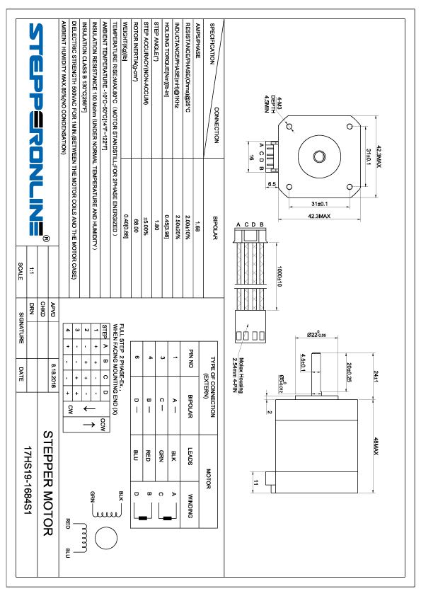
Bipolar Nema 17 stepper motor with step angle 1.8deg and size 42x42x48mm. It has 4 wires with 1m cable and 2.54mm pitch connector, each phase draws 1.68A, with holding torque 45Ncm (64oz.in).
Let's start with the name: Nema stands for National Electrical Manufacturers Association, and indicates that it is the association that established the standardization for this type of motor. I thought that the number 17 indicated some reference to power but it is limited to defining the size of the faceplate, in this case the length and width of both faceplates measure 42.3 mm or 1.665354 inches, an amount that is rounded to 1.7. In theory, these dimensions should be the same regardless of the manufacturer, in this way they ensure that it is possible to change the model without having to modify the dimensions of the machine that uses them.
An important thing to consider is the required positioning resolution (often expressed as degrees per step or step angle), the number of steps per revolution on stepper motors ranges from 4 to 400. These NEMA 17 motors have 1.8° degrees per step or 200 steps per revolution.
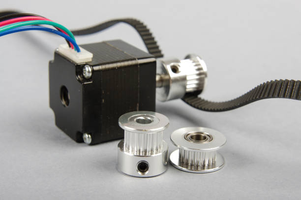
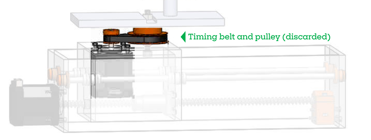
Another way to achieve high positioning resolution is with gearing, like those gears from 3d printers. We had originally considered using one of these gears with a pulley but it complicated the design and didn't offer significantly better results as we didn't need as much turning accuracy. On the final version we better put some kind of 3d printed bearing directly on the motor shaft. We took as inspiration a part of the machine design of the FabLab León of 2019 that incorporates a rotating surface using MDF and marbles, basically a laser-cut bearing. They did a great job of solving the spin problem with such a simple and effective solution.
There are three types of shafts: Round or "D" Shaft (these are available in a variety of standard diameters and there are many pulleys, gears and shaft couplers designed to fit. "D" shafts have one flattened side to help prevent slippage when high torques are involved), Geared shaft (some shafts have gear teeth milled right into them) and Lead-Screw Shaft (motors with these shafts are used to build linear actuators). We used one motor with D shaft for the spin and one with Lead-Screw for the linear motion.
There are two types of types of drivers: unipolar and bipolar. Unipolar drivers always energize the phases in the same way: one lead, the "common" lead, will always be negative, the other lead will always be positive. Unipolar drivers can be implemented with simple transistor circuitry. The disadvantage is that there is less available torque because only half of the coils can be energized at a time. Bipolar drivers use H-bridge circuitry to actually reverse the current flow through the phases. By energizing the phases with alternating the polarity, all the coils can be put to work turning the motor.
| Unipolar stepper motor | Bipolar stepper motor |
| Lower torque | Higher torque |
| Less retention | Greater retention due to its windings |
| Has a larger volume | Smaller |
| More expensive | Cheaper |
| Easier control by requiring only one power circuit | A more complicated control, which requires a board that includes power and spin control stages |
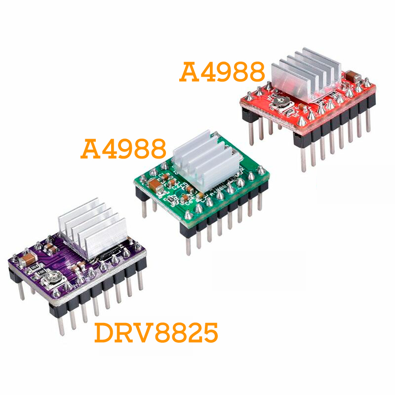
The use of these stepper motors requires drivers such as the A4988 or the DRV8825 that allow us to handle the high voltages and currents that these motors require, limit the current that flows through the motor and provide protections to prevent the electronics from being damaged. For their control they only require two digital outputs: one to indicate the direction of rotation and another to communicate that we want the motor to advance one step. On this machine we are using two A4988.
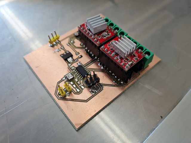
This is the controller board for our machine, it uses an ATTiny84 to send pulses to the two Pololu A4988 stepper driver breakout boards.
Finally, the main advantage of the A4988 driver is the ease on the programming as this only needs two pins and works quite good without the need of a library (but there are lots of them ready to do the hard job). We used this code from Last minute engineers to the first test of the driver and the motor.
    // Define pin connections & motor's steps per revolution
const int dirPin = 2;
const int stepPin = 3;
const int stepsPerRevolution = 200;

void setup()
{
	// Declare pins as Outputs
	pinMode(stepPin, OUTPUT);
	pinMode(dirPin, OUTPUT);
}
void loop()
{
	// Set motor direction clockwise
	digitalWrite(dirPin, HIGH);

	// Spin motor slowly
	for(int x = 0; x < stepsPerRevolution; x++)
	{
		digitalWrite(stepPin, HIGH);
		delayMicroseconds(2000);
		digitalWrite(stepPin, LOW);
		delayMicroseconds(2000);
	}
	delay(1000); // Wait a second

	// Set motor direction counterclockwise
	digitalWrite(dirPin, LOW);

	// Spin motor quickly
	for(int x = 0; x < stepsPerRevolution; x++)
	{
		digitalWrite(stepPin, HIGH);
		delayMicroseconds(1000);
		digitalWrite(stepPin, LOW);
		delayMicroseconds(1000);
	}
	delay(1000); // Wait a second
}
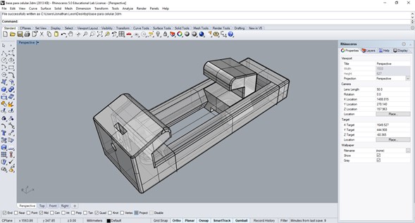
Files
You can download the files for the phone stand here: Rhino (with the first prototypes and the final version), STL (printed in one piece, just add supports on your slicer).