How to make (almost) anything.
Week 8. Embedded Programming
Work done in the Lab under the guidance of my remote Instructor to accomplish the weekly assignments.
This week I made some programming tests.
My weekly schedule:
| Wednesday, March 10 | Thursday, March 11 | Friday, March 12 | Saturday, March 13 | Sunday, March 14 | Monday, March 15 | Tuesday, March 16 |
| Global class | Data sheet reading | FabTinyISP reading | Arduino test | - | Microchip Studio test | Microchip Studio test |
Group assignment
For this Group assignment we made a comparison between the different MCU's that we have available in the laboratory. You can read it there.
Data sheet reading
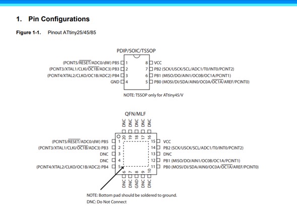
I started this assignment by reading the datasheet of my FabTinyISP controller, an AtTiny45. For me the most important information so far is the supply voltage (1.8 to 5.5v for 10MHz speed and 2.7 to 5.5v for 20Mhz), the consumption (300 uA when active), the memory available (4Kb for program memory flash, 256 bytes EEPROM and 256 bytes SRAM), the pin configuration diagram to be able to connect the other components correctly, and the architecture overview, which roughly explains the processes carried out by the processor.
Atmel-ICE and Microchip Studio test
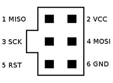
After reading the controller Datasheet I already had a basic notion of how to connect my board to an ISP using cables so I could start programming using Atmel-ICE. The most important pins for this exercise are MISO, MOSI, and RESET, conected to the AVR input on Atmel-ICE.

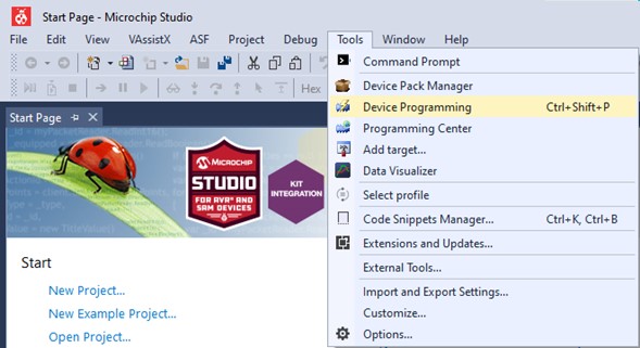
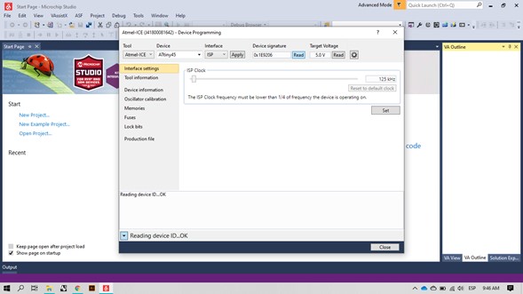
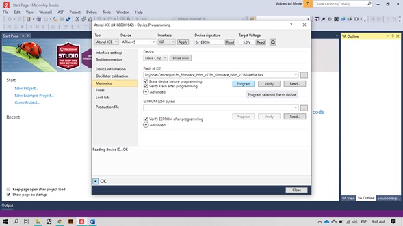
My first test was in Microchip Studio (formerly known as Atmel Studio). First I entered Device programming, connected the board and selected the correct controller and interface, clicking on the Read button the program connects to the board and makes a reading of its signature and its voltage, which roughly indicates that the components are correctly detected by the PC.
The programming is carried out from the Memories section, selecting a .HEX file that indicates to the controller the processes to carry out, I downloaded this and modified it in Brackets indicating that the communication would be carried out through Atmel-ICE.
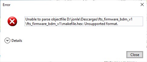
But the program showed an unsupported format error.
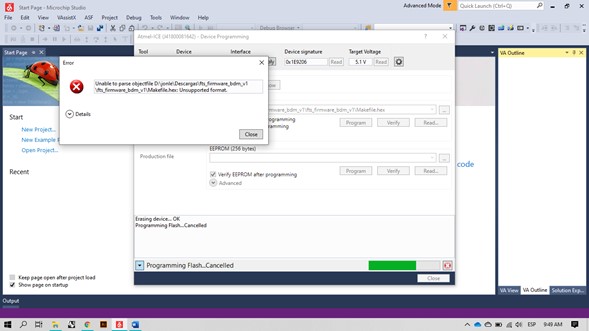
I started looking for the possible problems without getting a successful result: file extension, use of capital letters, use of lowercase letters, I tried downloading the firmware from another repository, I tried editing the code in Brackets in its last lines, I even checked again that the physical connection was correct, but nothing worked, so I tried with an Arduino board.
Arduino test
For this test I connected the board to the Arduino UNO.
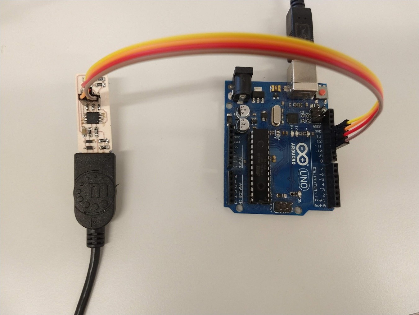
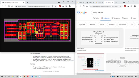
To make the connections correctly I used this pinout images, these summarize one of the most important parts of the data sheet.
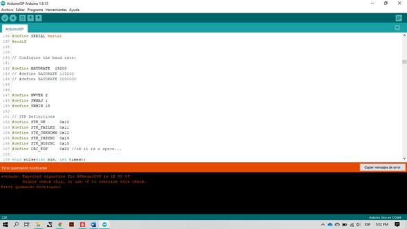
When burning the Bootloader with the Arduino (with processor) connected to the ISP it gave me the following error:
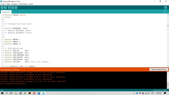
When burning the Bootloader with the Arduino (without processor) connected to the ISP it gave me the following error:
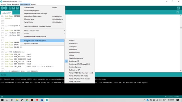
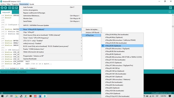
Checking the Arduino IDE options I realized that the problem was that I had not selected the board, the Arduino UNO was still activated instead of the ATtiny45. When burning the Bootloader with the processor in place, the operation was successful.
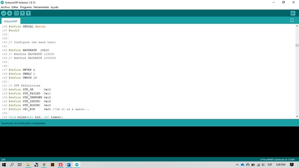
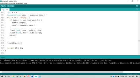
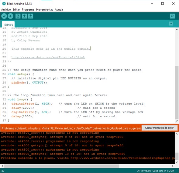
Unfortunately after burning the bootloader there was some problem with my board that did not let me upload the test sketch (Blink).
Raspberry
We tried to program the board in Windows from different computers, we installed lots of applications to test without success, so we had to look for a Linux computer because apparently the development environment was much simpler using it:
-Linux
For Ubuntu and other Debian-based distributions, enter the following command, followed by your password when prompted:
sudo apt install avrdude gcc-avr avr-libc make
-Windows
- Install Git
- Install the Atmel GNU Toolchain
- Install GNU Make
- Install avrdude
- Update your PATH
- Install Drivers for your Programmer
- Sanity Check
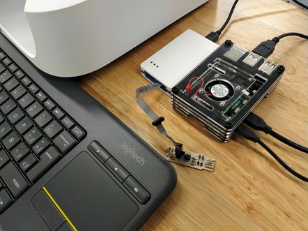
It is much easier to do it on Linux. As we didn't have any Linux computer (and a bootable USB did not allow us to keep the installed applications after restarting the computer), we tried using a Raspberry that we had on hand.
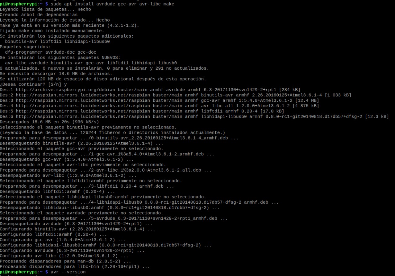
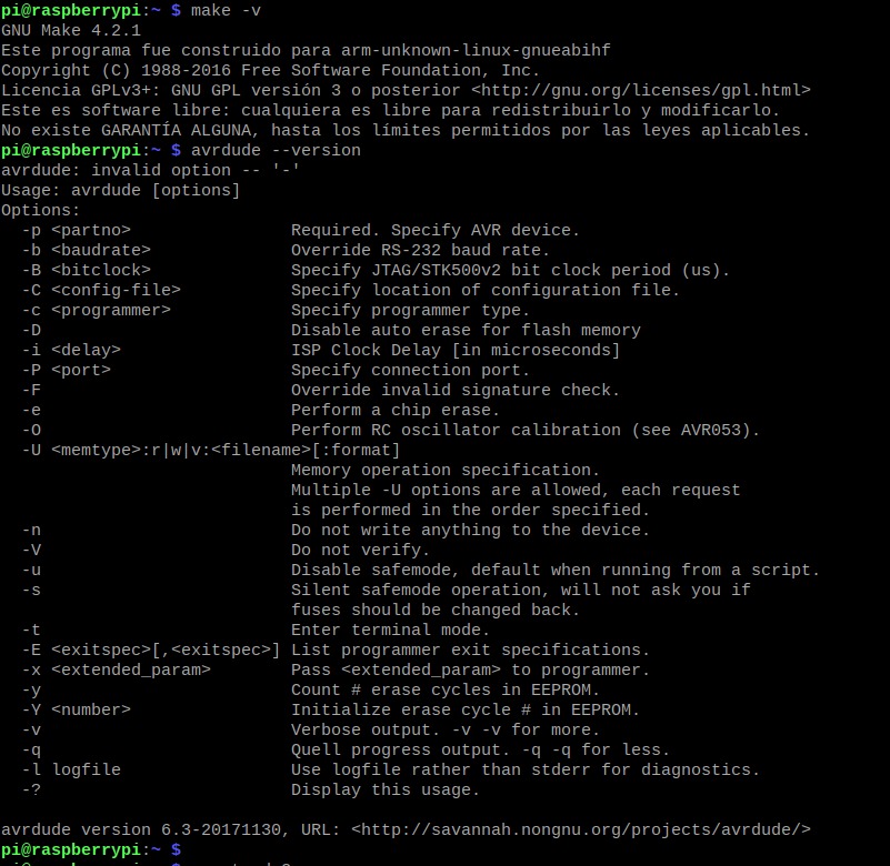
With the command sudo apt install avrdude gcc-avr avr-libc make the applications were installed on the Raspberry.
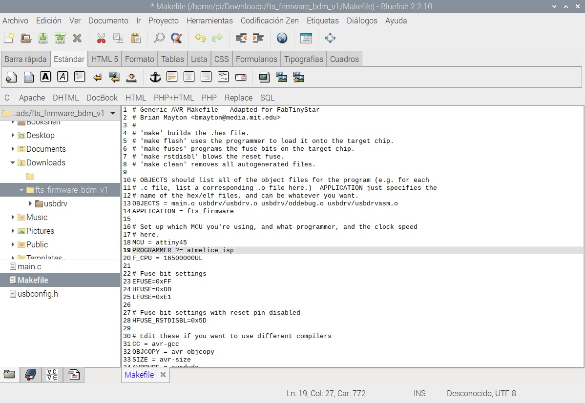
We downloaded the source code and extracted it to the root folder, executing the make command generated a .HEX file that will later be written to the chip.
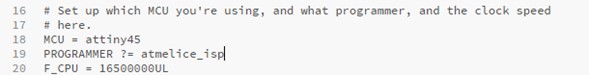
We edited the Makefile file to specify that the programmer we will use is an Atmel-ICE.
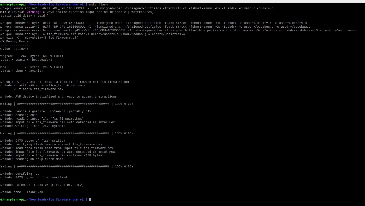
With the command make flash we erased the content of the chip and wrote the content of the .HEX file that we created earlier.
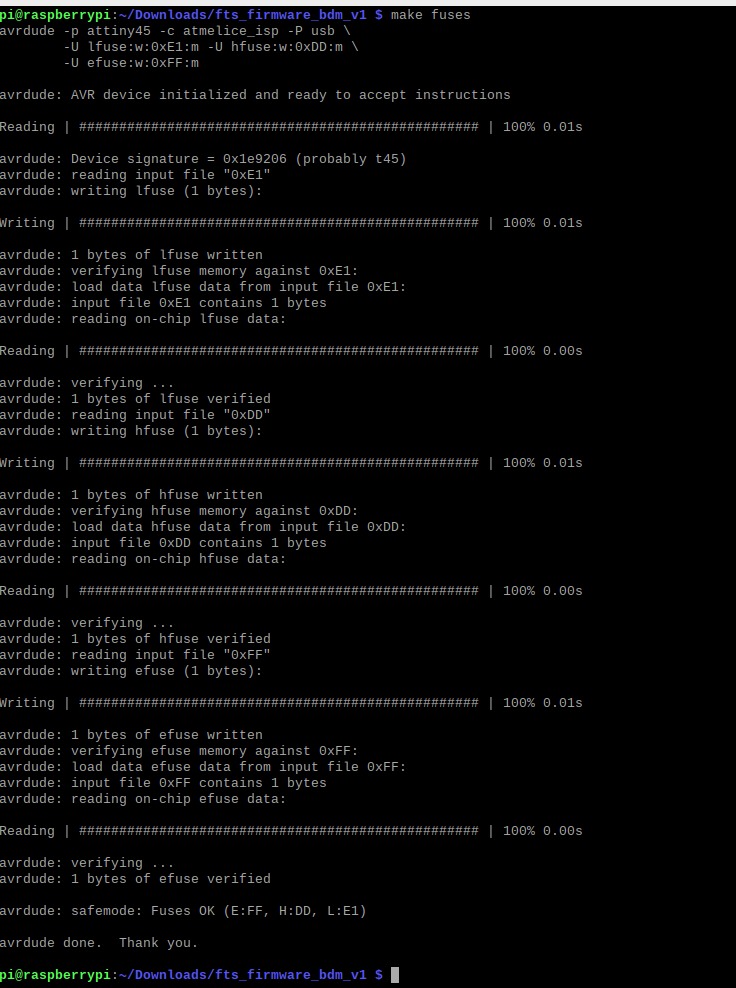
With the command make fuses we set the fuses that control where the microcontroller gets its clock source from.
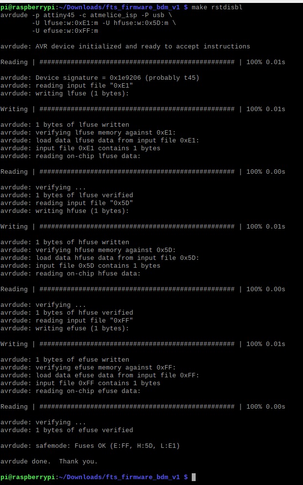
And finally we disabled the reset pint and turned it into a GPIO pin using the command make rstdisbl.
We physically removed the solder bridge that connects VCC with the programming pin.
To test the board as a programmer we uploaded my Mimic sketch on my echo board. If you press the button for 1 second, the LED flashes for intervals of 1 second.
The variables to use involve the pins corresponding to the LED and the button as well as their initial states (LED off and button normally closed), the initial interval of the blink and two time variables: one that stores the time that has passed since the last change in the state of the LED and another that stores the time with the button pressed. The Setup sets the button pin as an input and the LED pin as an output. The Loop checks if the button is pressed and stores the time upon press and release, then calculate the amount of time it was pressed and uses that value to make the led to blink at the same rate. This sketch uses millis instead of delays, you can read another example there.
//Echoboard: Attiny44, button and LED
//In this code the duration of the Blink is set by the time the button is pressed.

int ledPin = PA7; //Set the LED pin
int ledState = LOW; //Set LED initial state
long ledStart = 0;  //Last time the LED was updated
long ledBlink = 1000;  //LED blink interval
int buttonPin = PA3;  //Set the button pin
int buttonState = HIGH; //Set the button initial state
long buttonPressTime = 0; //Time with the button pressed


void setup()
{
 pinMode(buttonPin, INPUT); //Set the button pin as an input
 pinMode(ledPin, OUTPUT); //Set the LED pin as an output
}

void loop()
{
 buttonState = digitalRead(buttonPin); //Read the state of the button pin
   if (buttonState==LOW && buttonPressTime==0) { //Check if the button is pressed
     buttonPressTime = millis();  //Check the time with the button pressed
   }
   if (buttonState==HIGH && buttonPressTime!=0) { //Check if the button is no longer pressed
     ledBlink = millis() - buttonPressTime;  //Sets the new interval for the blink from the subtraction of the execution time of the program minus the time with the button pressed
     buttonPressTime = 0;  //Reset the timer, ready for a new time reading
   }
   if (millis() - ledStart > ledBlink) { //Check if the time the button was pressed is less than the blink interval
     ledStart = millis(); //Update ledStart
     if (ledState == LOW) //Check if the previous ledState was LOW
       ledState = HIGH; //Set the new ledState on HIGH to blink ON
     else
       ledState = LOW; //Set the new ledState on LOW to blink OFF
     digitalWrite(ledPin, ledState); //Set the new ledState on the ledPin, blinking the LED
   }
}
Update with SAMD11c for 2022 evaluation standards
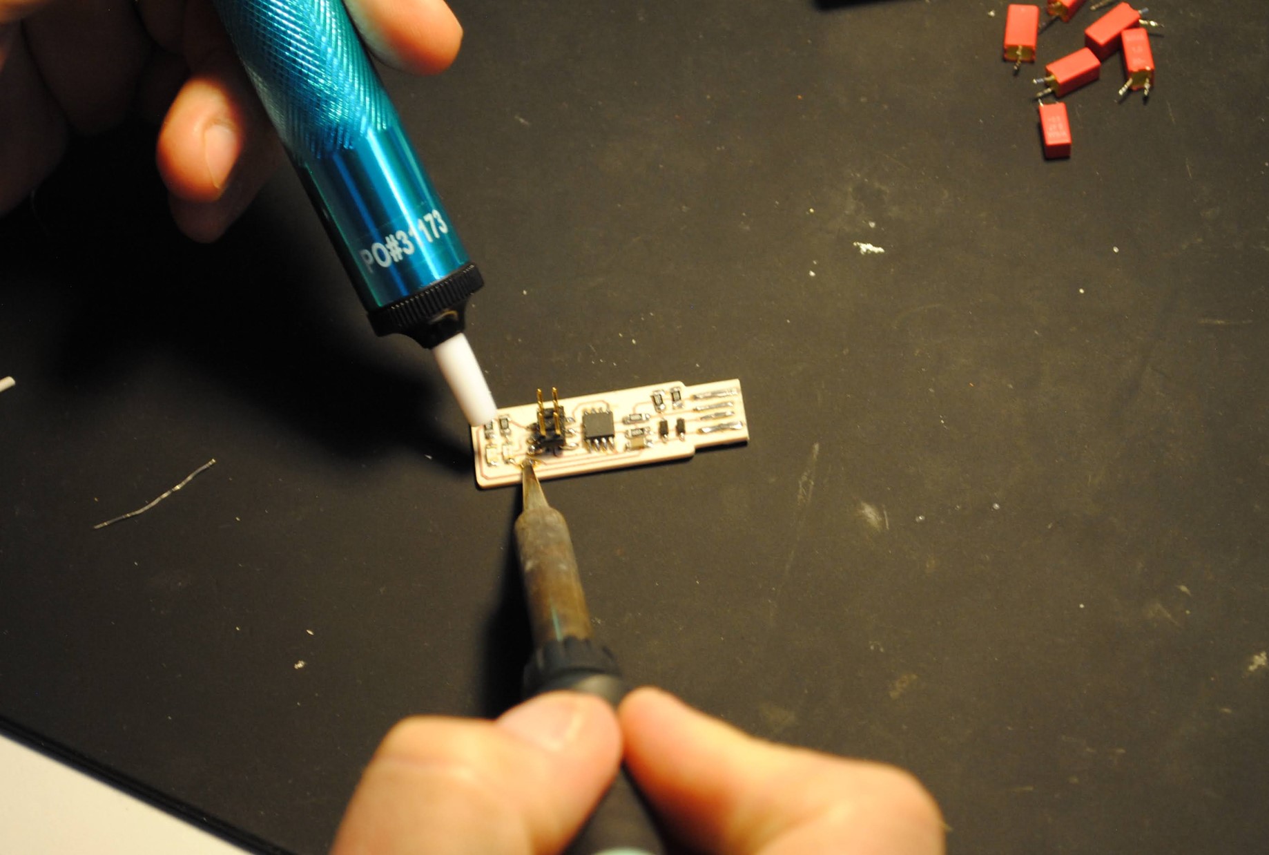
As ATtiny44 and ATtiny45 are obsolete now I made a board using a new generation processor: SAMD11c. It can be programmed directly by USB (only a SWD programmer is needed to burn the bootloader the first time), its a great replacement for an Arduino board (with some exceptions due to low memory and some libraries that are not yet compatible with ARM-based processors).
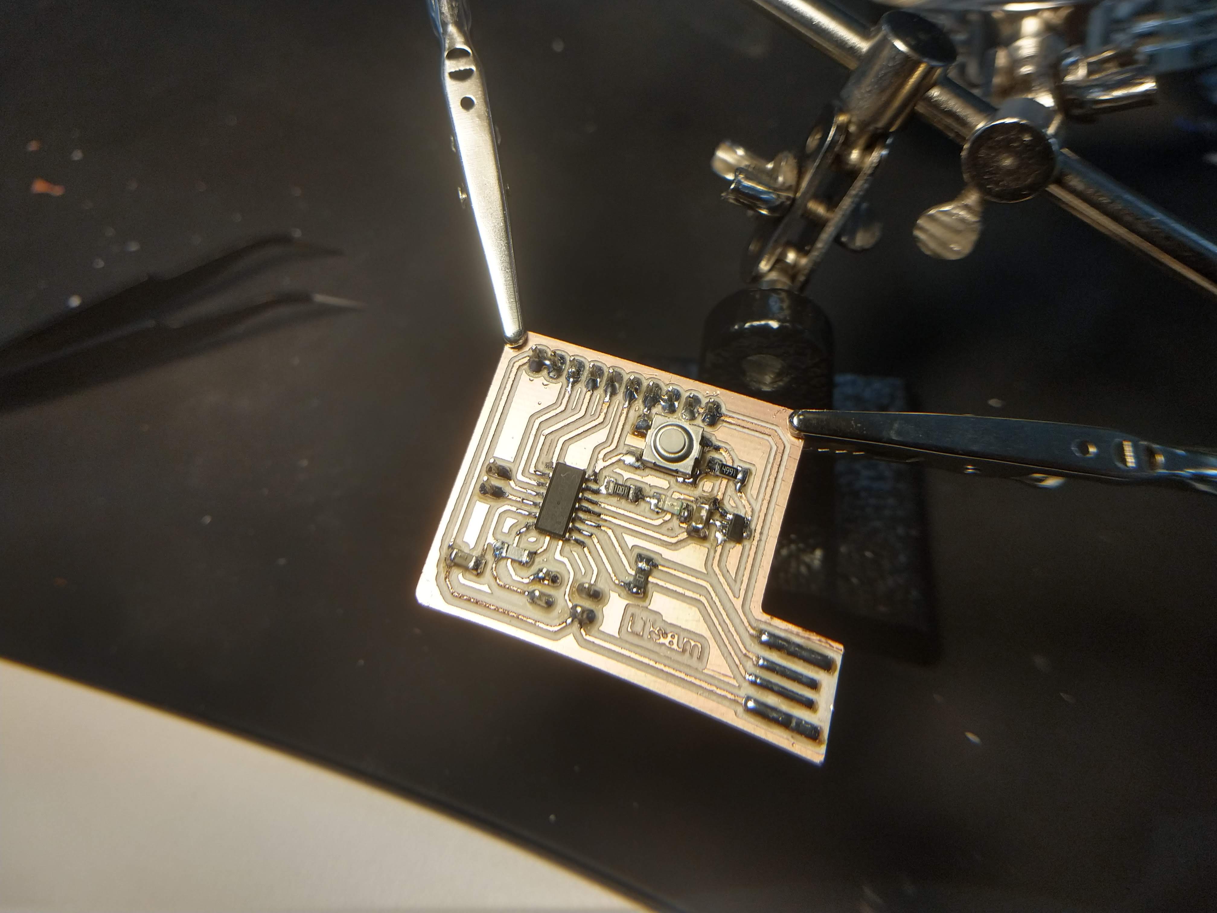
Programming this board was MUCH EASIER than the ATtiny45: once I finished soldering the components I just had to flash the processor using a SWD programmer that our instructor kindly sent us from Mexico. I connected the programmer to the PC and the new board on the CLK, DIO, RST and GND ports (with an external power source).

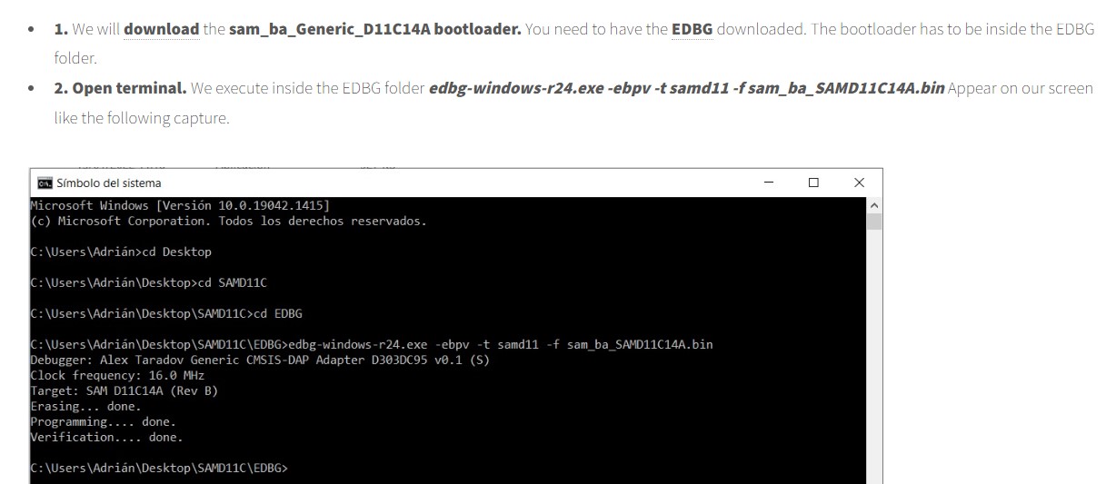
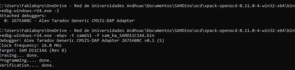
I followed the tutorial by Adrán Torres and ran EDBG in the terminal with the command:
edbg-windows-r24.exe -ebpv -t samd11 -f sam_ba_SAMD11C14A.bin
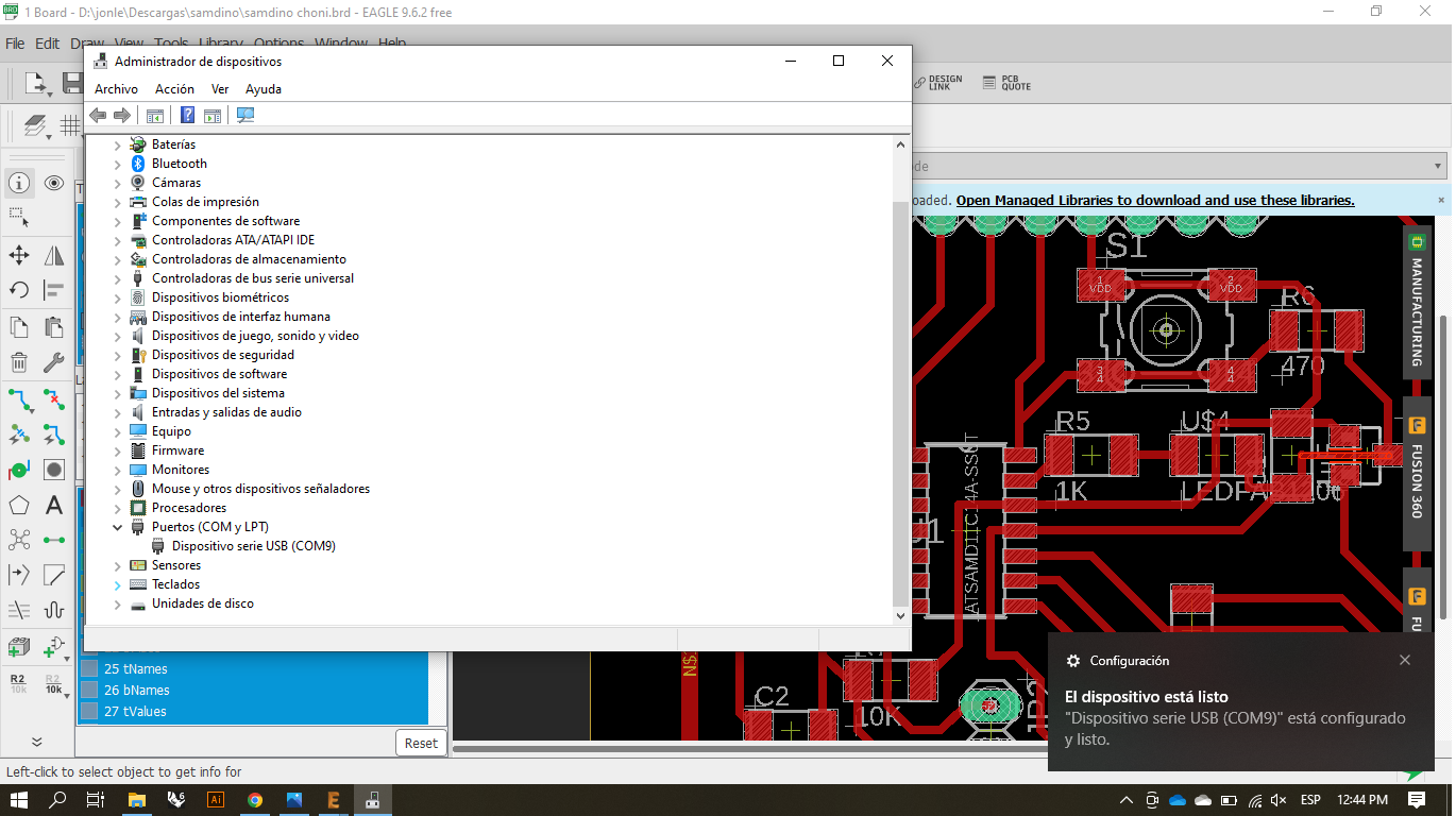
When connecting the board to my laptop using a USB 2.0 extension it was recognized as a USB serial device.
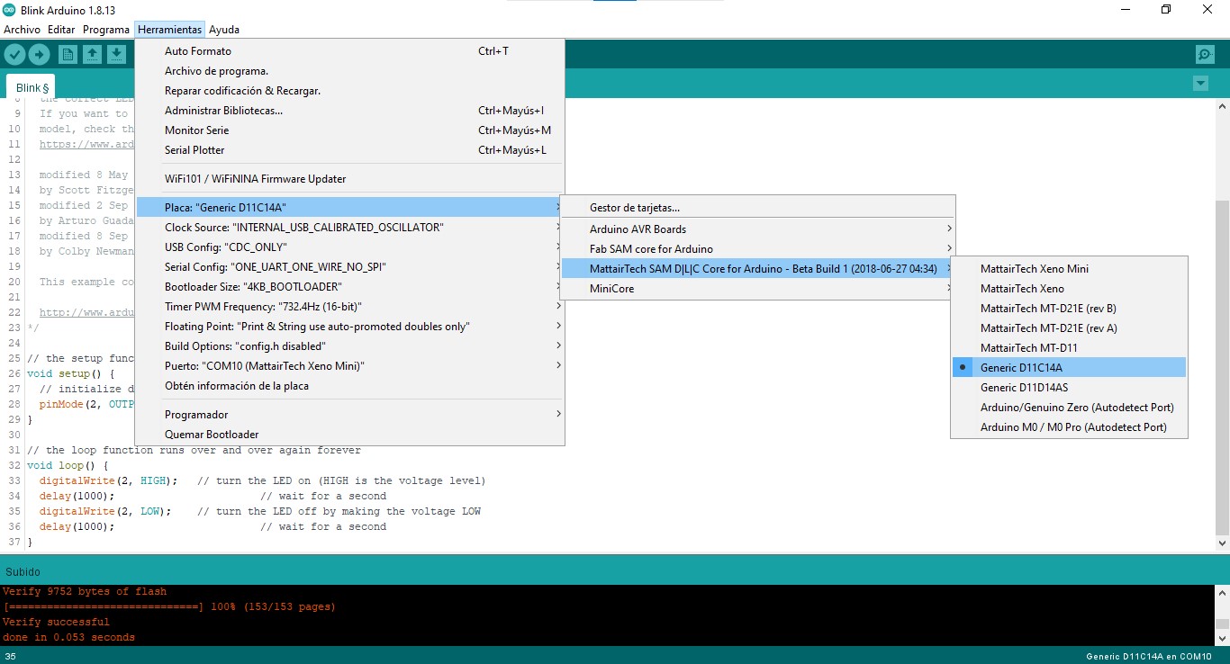
With this bootloader it is possible to upload sketches directly from Arduino IDE via USB without needing an external programmer, you just have to select the correct board. Install the boards library from Mattairtech using this URL.
Here is controlling an RGB LED via serial communication from my laptop the interface I made using Processing.
Here is displaying text messages on a 8x8 LED matrix.
Final project update
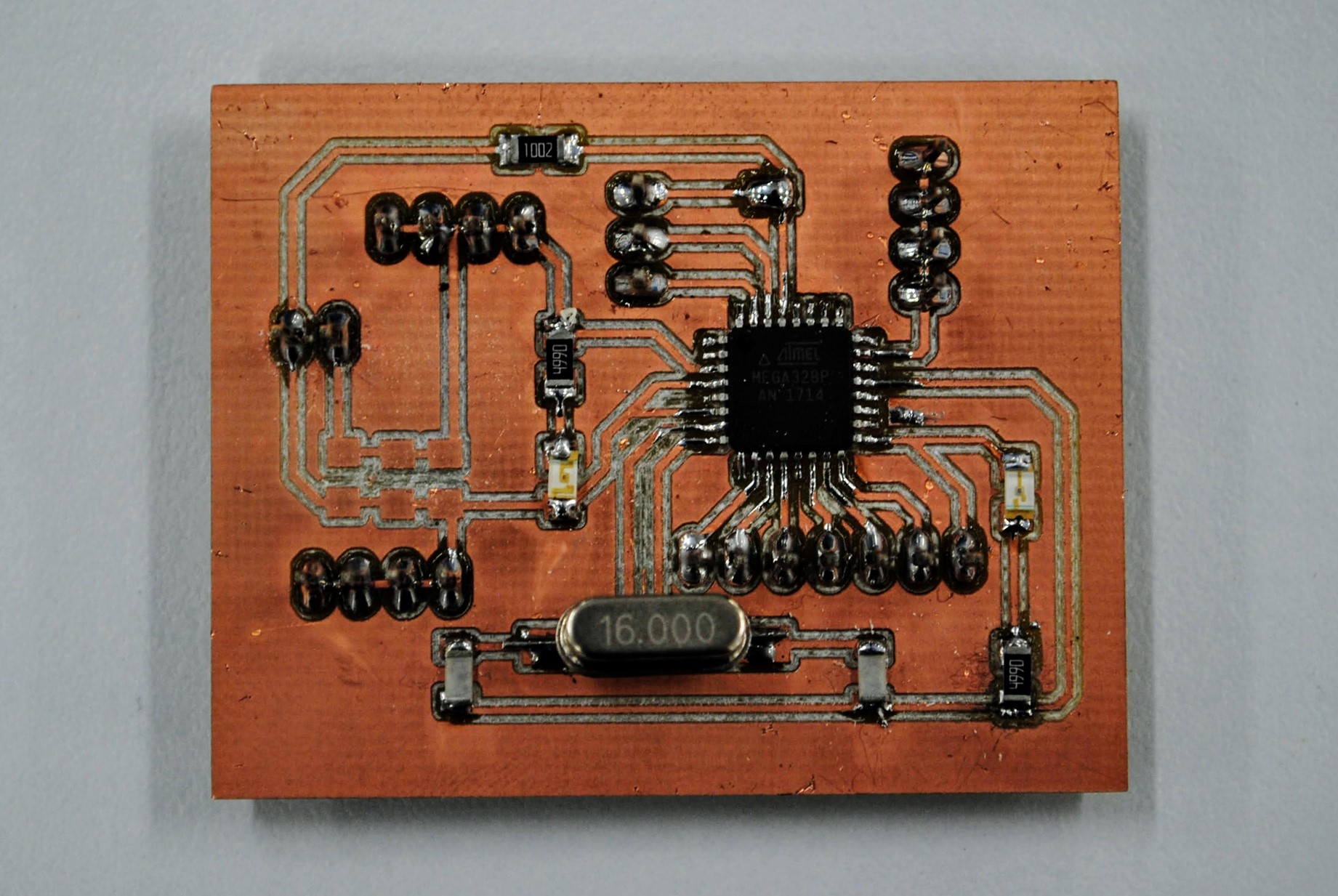
For the board of my final project I'm using ATmega328P as processor to be able to use Arduino libraries.
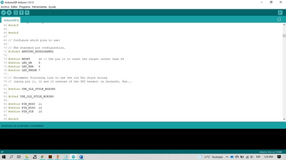
I burned the bootloader using an Arduino Uno as ISP. I made the connections as indicated in the ArduinoISP sketch in OLD_STYLE_WIRING mode: RESET (PIN 10), MOSI (PIN 11), MISO (PIN 12), SCK (PIN 13).
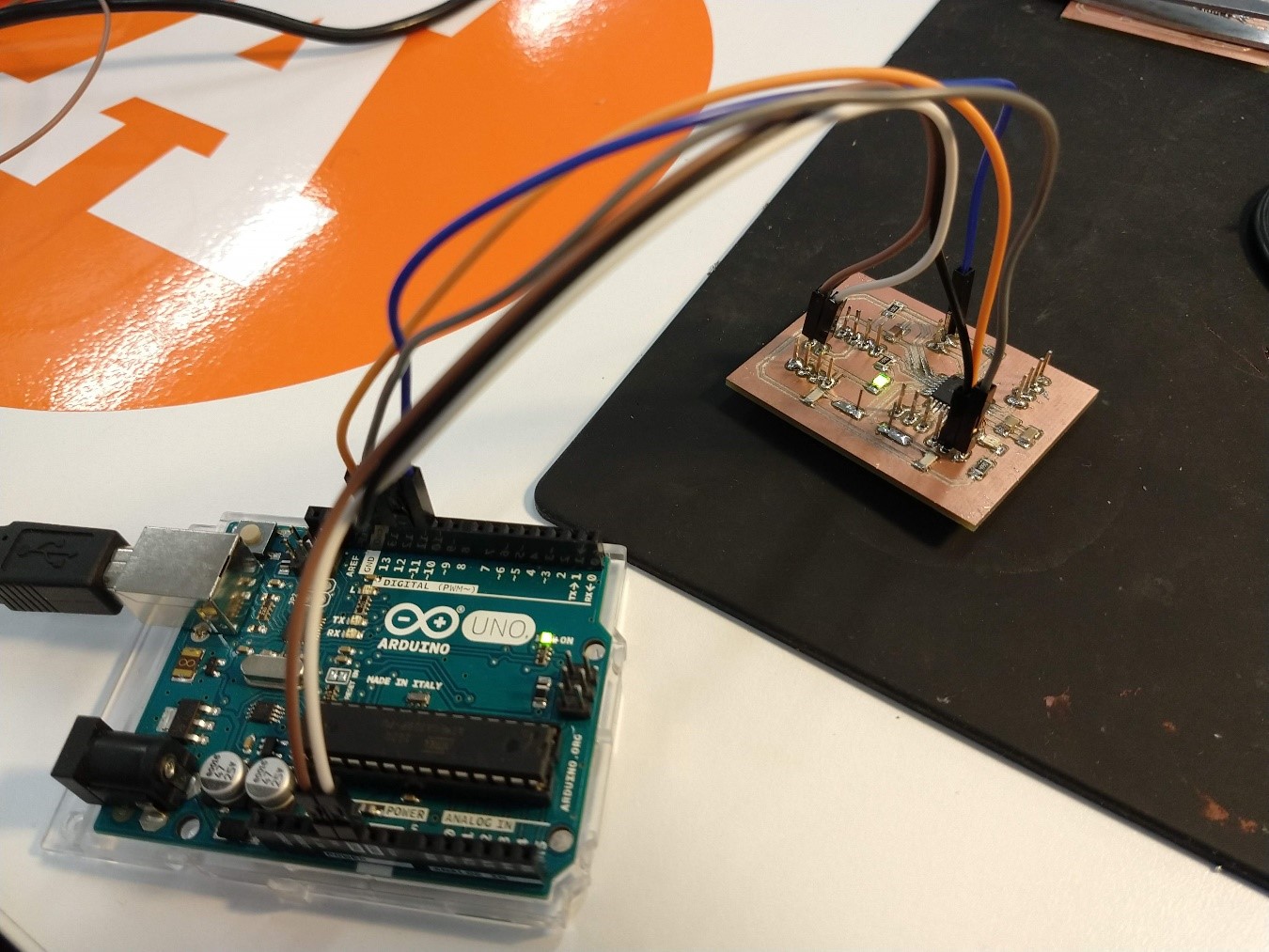
To test my board I successfully uploaded a Blink sketch from Arduino IDE examples.
Now I'm able to make any Arduino project with this board!
Files
You can download the INO file for Mimic here, for displaying text on the 8x8 LED matrix here, and the basic Blink here.
|
For this assignment I:
|