How to make (almost) anything.
Week 14. Interface and Application Programming.
Work done in the Lab under the guidance of my remote Instructor to accomplish the weekly assignments.
This week I made a Bluetooth interface for my final project with Blynk, made a GUI for RGB LED control using Processing and modified a game with MIT App Inventor.
Group assignment
This week we compared three tool options for application programming, you can read it there.
Blynk
For this assignment I explored the possibility of controlling a board via Bluetooth signals for which I used Blynk, an application for mobile devices that is very easy to use.
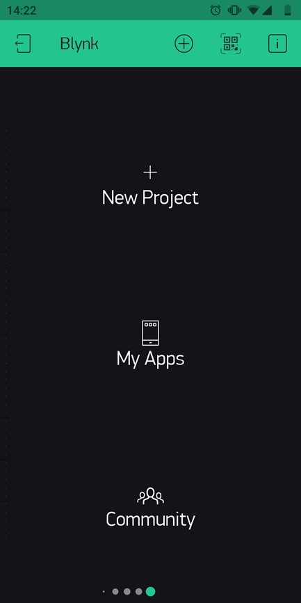
In the Android application I generated a new project and called it "Bluetooth" to easily recognize it, I added a Bluetooth module and a push button to it.
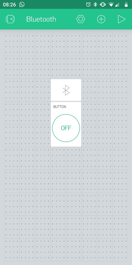
I assigned the pin # 6 to the button on the project to replace the physical button I was using at the time with the board I had on hand, an Arduino UNO connected to my lamp's neopixels. The Bluetooth module uses RX/TX pins so I had to load the sketch and then connect the module (if the module is connected the sketch cannot be loaded by Arduino IDE).
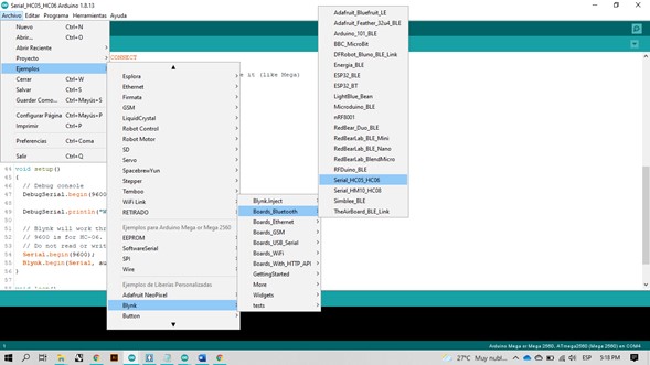
That is the only thing to do in the mobile application. To connect it to the board I opened one of Blynk's example code in the Arduino IDE and joined it with another Neopixels effects demo code.
//A few sample animations for Neopixels with bluetooth control over Blynk using Arduino + HC06 BT module as an input. The button does not interrupt an
// animation in-progress, it works only when idle. This code needs Neopixel and Blynk libraries.
#include <Adafruit_NeoPixel.h>
#ifdef __AVR__
#include <avr/power.h> // Required for 16 MHz Adafruit Trinket
#endif
#define BLYNK_USE_DIRECT_CONNECT
// You could use a spare Hardware Serial on boards that have it (like Mega)
#include <SoftwareSerial.h>
SoftwareSerial DebugSerial(2, 3); // RX, TX
#define BLYNK_PRINT DebugSerial
#include <BlynkSimpleSerialBLE.h>
// You should get Auth Token in the Blynk App.
// Go to the Project Settings (nut icon).
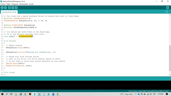
char auth[] = "YOUR TOKEN";
// Digital IO pin connected to the button. This will be driven with a
// pull-up resistor so the switch pulls the pin to ground momentarily.
// On a high -> low transition the button press logic will execute.
#define BUTTON_PIN 3 // Select PIN 3 on the Button settings on Blynk
#define PIXEL_PIN 6 // Digital IO pin connected to the NeoPixels.
#define PIXEL_COUNT 5 // Number of NeoPixels
// Declare our NeoPixel strip object:
Adafruit_NeoPixel strip(PIXEL_COUNT, PIXEL_PIN, NEO_GRB + NEO_KHZ800);
// Argument 1 = Number of pixels in NeoPixel strip
// Argument 2 = Arduino pin number (most are valid)
// Argument 3 = Pixel type flags, add together as needed:
// NEO_KHZ800 800 KHz bitstream (most NeoPixel products w/WS2812 LEDs)
// NEO_KHZ400 400 KHz (classic 'v1' (not v2) FLORA pixels, WS2811 drivers)
// NEO_GRB Pixels are wired for GRB bitstream (most NeoPixel products)
// NEO_RGB Pixels are wired for RGB bitstream (v1 FLORA pixels, not v2)
// NEO_RGBW Pixels are wired for RGBW bitstream (NeoPixel RGBW products)
boolean oldState = HIGH;
int mode = 0; // Currently-active animation mode, 0-9
void setup() {
// Debug console
DebugSerial.begin(9600);
DebugSerial.println("Waiting for connections...");
// Blynk will work through Serial
// 9600 is for HC-06. For HC-05 default speed is 38400
// Do not read or write this serial manually in your sketch
Serial.begin(9600);
Blynk.begin(Serial, auth);
pinMode(BUTTON_PIN, INPUT_PULLUP);
strip.begin(); // Initialize NeoPixel strip object (REQUIRED)
strip.show(); // Initialize all pixels to 'off'
}
void loop() {
Blynk.run();
// Get current button state.
boolean newState = digitalRead(BUTTON_PIN);
// Check if state changed from high to low (button press).
if((newState == LOW) && (oldState == HIGH)) {
// Short delay to debounce button.
delay(20);
// Check if button is still low after debounce.
newState = digitalRead(BUTTON_PIN);
if(newState == LOW) { // Yes, still low
if(++mode > 8) mode = 0; // Advance to next mode, wrap around after #8
switch(mode) { // Start the new animation...
case 0:
colorWipe(strip.Color( 0, 0, 0), 50); // Black/off
break;
case 1:
colorWipe(strip.Color(255, 255, 255), 50); // Red
break;
case 2:
colorWipe(strip.Color( 0, 255, 0), 50); // Green
break;
case 3:
colorWipe(strip.Color( 0, 0, 255), 50); // Blue
break;
case 4:
theaterChase(strip.Color(127, 127, 127), 50); // White
break;
case 5:
theaterChase(strip.Color(127, 0, 0), 50); // Red
break;
case 6:
theaterChase(strip.Color( 0, 0, 127), 50); // Blue
break;
case 7:
rainbow(10);
break;
case 8:
theaterChaseRainbow(50);
break;
}
}
}
// Set the last-read button state to the old state.
oldState = newState;
}
// Fill strip pixels one after another with a color. Strip is NOT cleared
// first; anything there will be covered pixel by pixel. Pass in color
// (as a single 'packed' 32-bit value, which you can get by calling
// strip.Color(red, green, blue) as shown in the loop() function above),
// and a delay time (in milliseconds) between pixels.
void colorWipe(uint32_t color, int wait) {
for(int i=1; i<strip.numPixels(); i++) { // For each pixel in strip...
strip.setPixelColor(i, color); // Set pixel's color (in RAM)
strip.show(); // Update strip to match
delay(wait); // Pause for a moment
}
}
// Theater-marquee-style chasing lights. Pass in a color (32-bit value,
// a la strip.Color(r,g,b) as mentioned above), and a delay time (in ms)
// between frames.
void theaterChase(uint32_t color, int wait) {
for(int a=0; a<10; a++) { // Repeat 10 times...
for(int b=0; b<3; b++) { // 'b' counts from 0 to 2...
strip.clear(); // Set all pixels in RAM to 0 (off)
// 'c' counts up from 'b' to end of strip in steps of 3...
for(int c=b; c<strip.numPixels(); c += 3) {
strip.setPixelColor(c, color); // Set pixel 'c' to value 'color'
}
strip.show(); // Update strip with new contents
delay(wait); // Pause for a moment
}
}
}
// Rainbow cycle along whole strip. Pass delay time (in ms) between frames.
void rainbow(int wait) {
// Hue of first pixel runs 3 complete loops through the color wheel.
// Color wheel has a range of 65536 but it's OK if we roll over, so
// just count from 0 to 3*65536. Adding 256 to firstPixelHue each time
// means we'll make 3*65536/256 = 768 passes through this outer loop:
for(long firstPixelHue = 0; firstPixelHue < 3*65536; firstPixelHue += 256) {
for(int i=0; i<strip.numPixels(); i++) { // For each pixel in strip...
// Offset pixel hue by an amount to make one full revolution of the
// color wheel (range of 65536) along the length of the strip
// (strip.numPixels() steps):
int pixelHue = firstPixelHue + (i * 65536L / strip.numPixels());
// strip.ColorHSV() can take 1 or 3 arguments: a hue (0 to 65535) or
// optionally add saturation and value (brightness) (each 0 to 255).
// Here we're using just the single-argument hue variant. The result
// is passed through strip.gamma32() to provide 'truer' colors
// before assigning to each pixel:
strip.setPixelColor(i, strip.gamma32(strip.ColorHSV(pixelHue)));
}
strip.show(); // Update strip with new contents
delay(wait); // Pause for a moment
}
}
// Rainbow-enhanced theater marquee. Pass delay time (in ms) between frames.
void theaterChaseRainbow(int wait) {
int firstPixelHue = 0; // First pixel starts at red (hue 0)
for(int a=0; a<30; a++) { // Repeat 30 times...
for(int b=0; b<3; b++) { // 'b' counts from 0 to 2...
strip.clear(); // Set all pixels in RAM to 0 (off)
// 'c' counts up from 'b' to end of strip in increments of 3...
for(int c=b; c<strip.numPixels(); c += 3) {
// hue of pixel 'c' is offset by an amount to make one full
// revolution of the color wheel (range 65536) along the length
// of the strip (strip.numPixels() steps):
int hue = firstPixelHue + c * 65536L / strip.numPixels();
uint32_t color = strip.gamma32(strip.ColorHSV(hue)); // hue -> RGB
strip.setPixelColor(c, color); // Set pixel 'c' to value 'color'
}
strip.show(); // Update strip with new contents
delay(wait); // Pause for a moment
firstPixelHue += 65536 / 90; // One cycle of color wheel over 90 frames
}
}
}
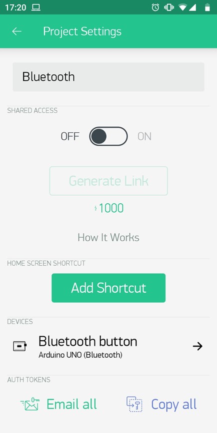
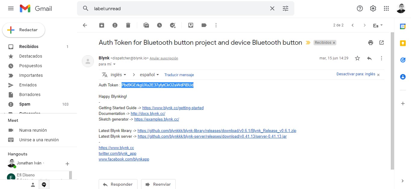
It is important to place the Auth token from the Blynk project in the Arduino IDE so that the communication between the two devices is validated. This token is sent by mail or can be copied from the application.
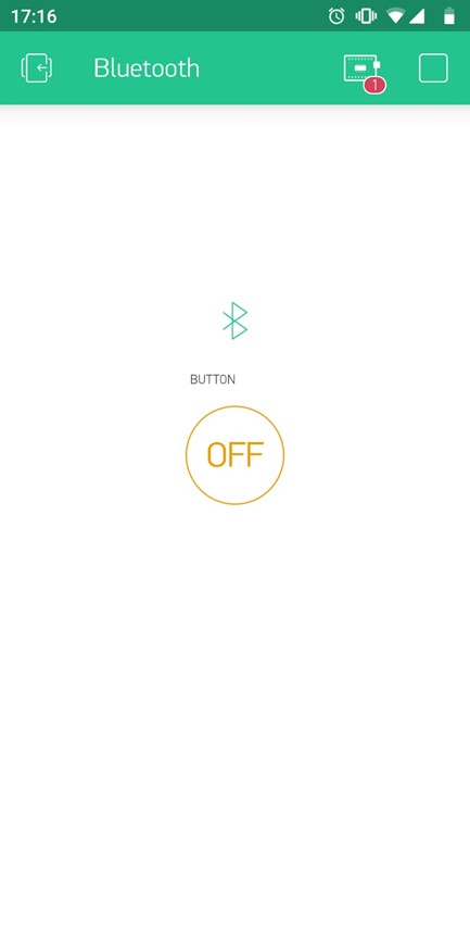
The phone connects to the BT module when the app is active and the LED stops flashing.
Processing
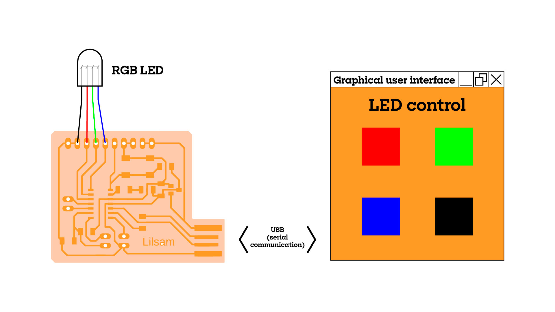
For a less automated alternative I used Processing, a programming language widely used by visual artists. I had never tried it but I instantly liked getting into a familiar environment because both the structure of the sketch and the user interface is very similar to Arduino (and the first tutorial I read was directly on the Arduino page so combining my existing codes was very easy). My goal was to create a graphical interface that would control some Arduino outputs using serial communication, I tried to control my neopixels but couldn't find a SAMD11c compatible library, so I did my tests with just one RGB LED.
The basic sketch on Processing is made up of two parts: setup (which runs only once) and draw (which runs in a loop during program execution. As I mentioned before, the syntax is very similar to Arduino, the lines of code are executed in order from top to bottom and all variables and functions must specify their parameters between parentheses or curly brackets. In this example I set up an 400 x 400 pixels canvas, give it an orange background color, and draw an ellipse at the exact mouse coordinates.
void setup (){
    size (400,400)
}

void draw (){
    background(232,139,32)
    ellipse(mouseX,mouseY,50,50)
}
This slightly more complex example includes a rectangle that functions as a button. When pressed, its color changes, and the legend "The button is pressed" appears in the command bar.
float x = 175;
float y = 210;
float w = 150;
float h = 80;
void setup(){
 size(500,500);
}

void draw(){
 background(232, 139, 32);
 rect(x,y,w,h);
 fill(202, 109, 2);
 if(mousePressed){
  if(mouseX>x && mouseX <x+w && mouseY>y && mouseY <y+h){
   println("The button is pressed");
   fill(252, 159, 52);
  }
 }
}
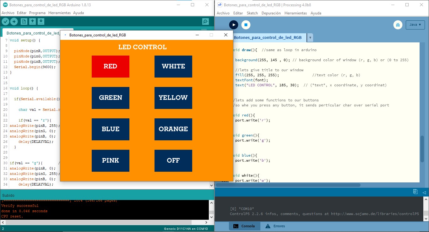
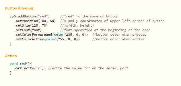
It is very easy to create the buttons in Processing but it is a bit tedious to manually write the coordinates of each of them (unless you use an array) and then manually configure each of the responses, to help me with the structure of the GUI and the actions of the buttons I used ControlP5, a library that is created precisely to facilitate the design of user interfaces. In this way it is enough to specify the parameters of the buttons and link them with functions to be carried out.
Following the examples on the Arduino page, I integrated serial communication into my code so that both sketches could interact. It's amazing how simple the code was, it basically just reads the input and prints the value to the serial monitor so that Processing can read it and act in response.
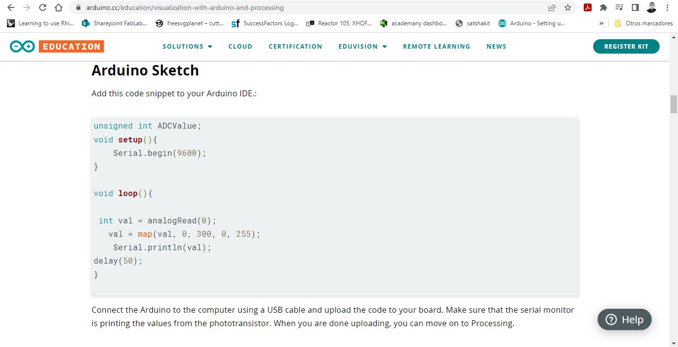
The code is divided into two parts: in Processing a layout with eight buttons is generated, pressing any of them writes a specific value in the serial monitor (the first letter of the color name), in Arduino the values that appear in the serial monitor assign variables according to each of the cases' numerical values (from 0 to 255) and those are assigned to the three channels of the LED (R,G,B) so that it lights up with the assigned color.
I'm still looking for a way to control neopixels in this way but at the moment it's only compatible with Arduino since I haven't found libraries compatible with ARM processors.
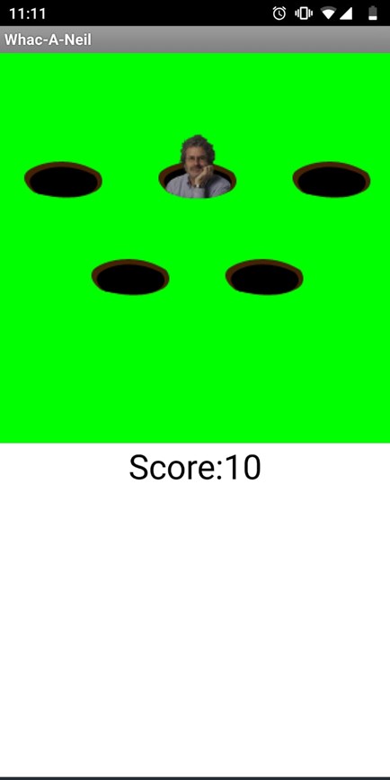
MIT App Inventor
For the group assignment I tried MIT App Inventor. I like to play Whac-A-Mole with my little cousin, so I modified one of the example projects on the page to see how difficult it was to make my own version using my favorite picture of my favorite teacher.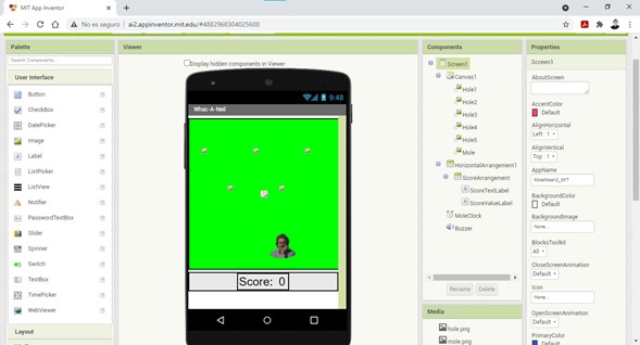
Files
You can download the .ino code for Blynk and neopixels here.
You can download the .ino and .pde codes for LED control GUI here.
You can download the Android .apk file here.
|
For this assignment I:
|