Networking and Communications
Assignment:
Group assignment:
- send a message between two projects.
Individual assignment
design, build, and connect wired or wireless node(s) with network or bus addresses.
Assignment:
For this weeks assignment, I will use Serial UART Connection to communicate between two Arduinos, and I will use I2C connection to connect an LCD to my Arduino, Then I will use the Bluetooth module to communicate with my arduino.
SERIAL UART COMUNICATION
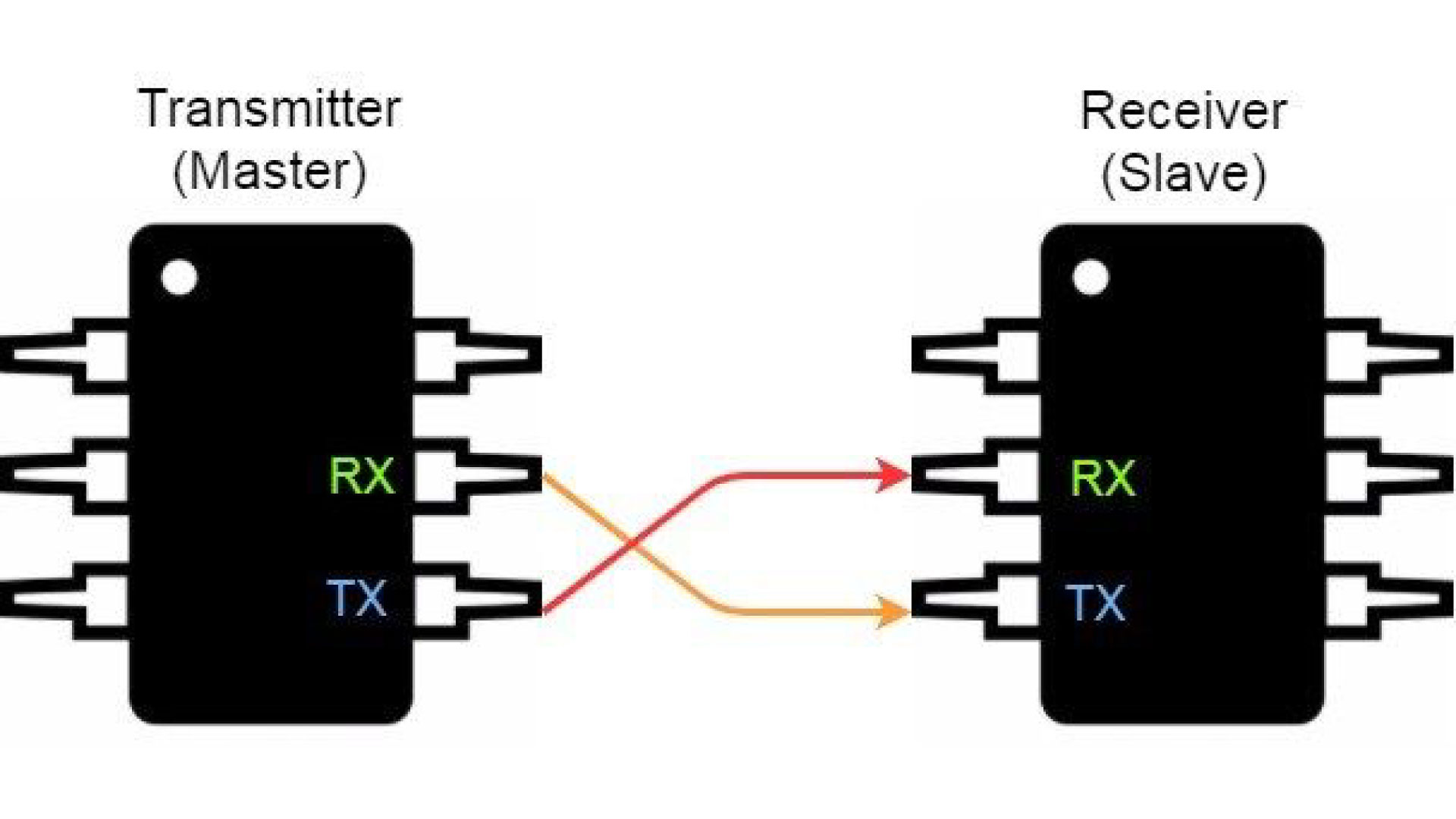
UART stands for Universal Asynchronous Reception and Transmission. It is a wired communication process that transmits/recieves data one bit at a time over hardware serial channles (Transmitter from device one to reciever from device two and vice versa). some microcontrollers have more than one hardware serial channels, in my case, the ATmega328 only has one TX and one RX, but we can use a library called Software serial, which gives us the ability to use other ports as serial communication boards.
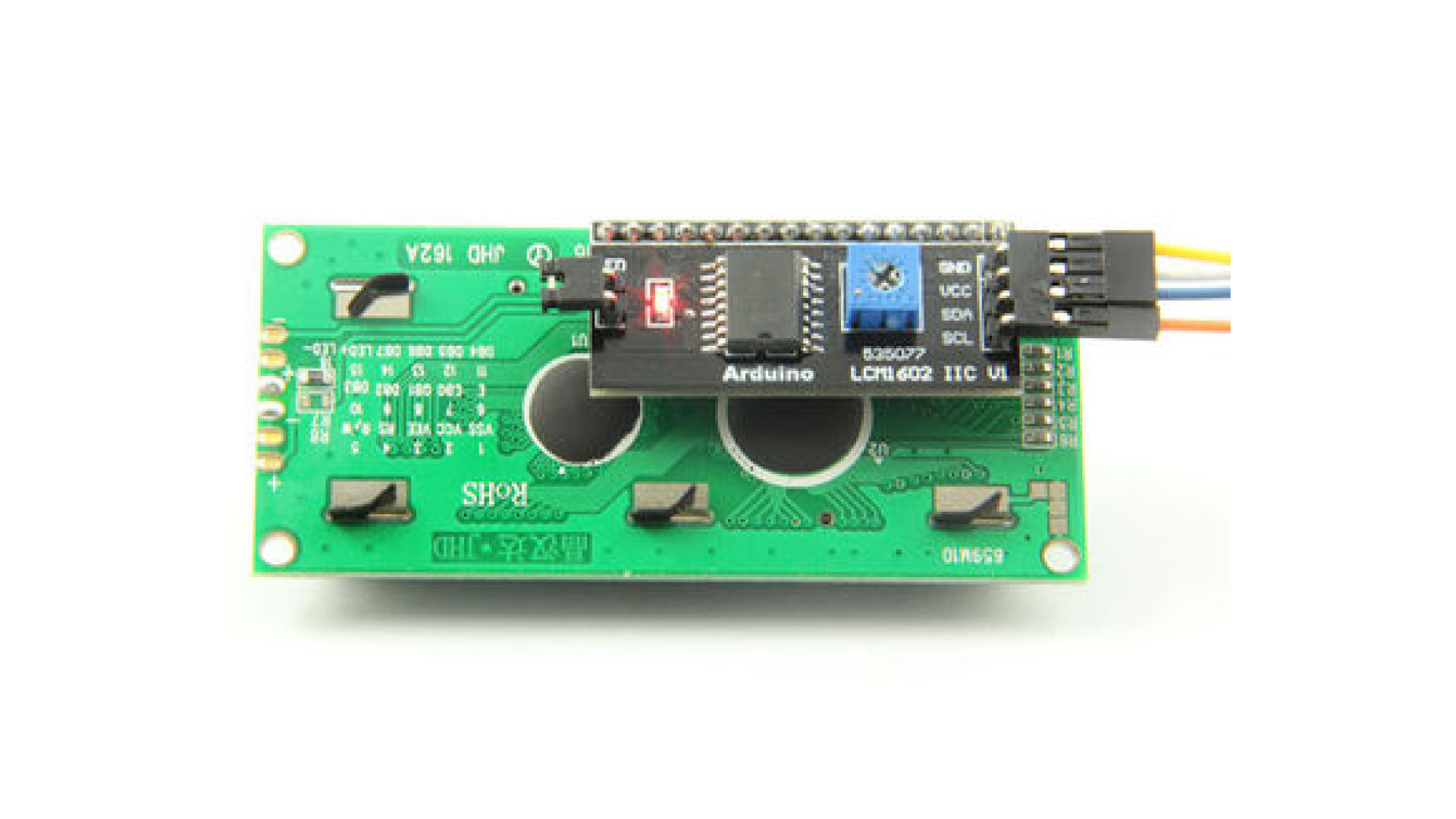
I2C COMUNICATION
With I2C, multiple slaves can be connected to a single master, and you can have multiple masters controlling single, or multiple slaves. This is really useful when you want to have more than one microcontroller logging data to a single memory card or displaying text to a single LCD. I2C also uses two wires to transmit data between two devices
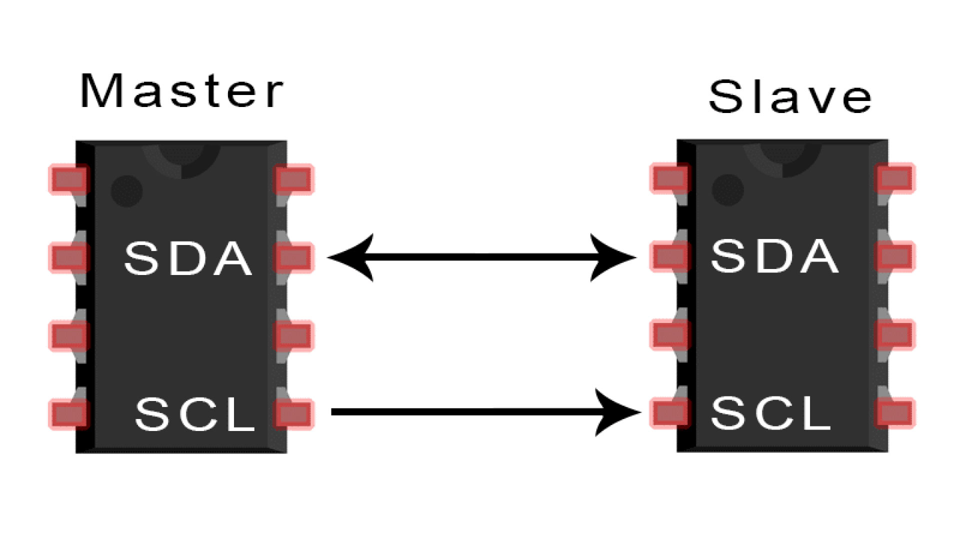
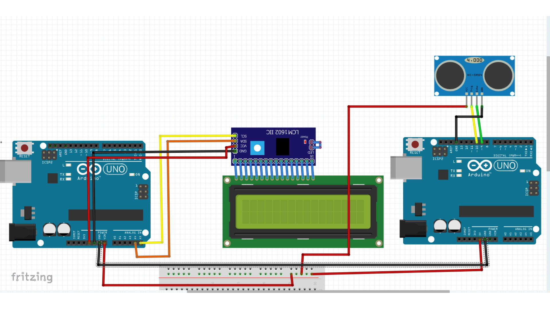
So, I connected two Arduino devices using UART communication using hardware serial TX and RX, note that the transmitter of the master should be connected to the reciever of the slave. I connected an ultrasonic distance sensor to the master, and an LCD to the slave to display the reedinngs. I used I2C connection to connect the LCD to the Arduino, this is accomplished using the I2C module, it is really useful since it shrinks the usage of wires to four wires including GND and VCC.
Below iis the connection of the devices.
And this is the code used:
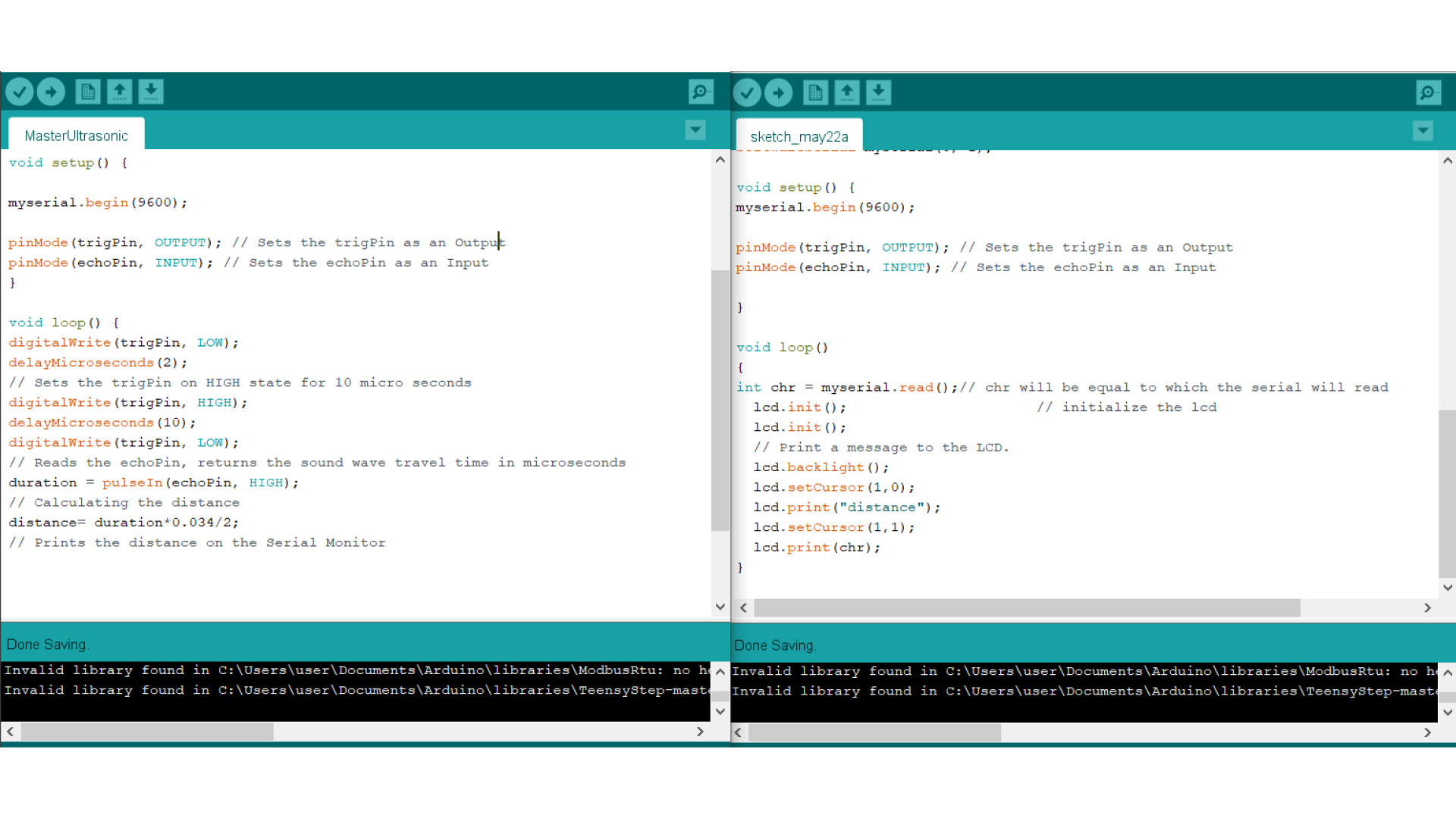
Note: You will not be able to upload your code to Arduino if the TX and RX are connected, remove them, upload, then connect the wires.
And here we can see the results:
Bluetooth connection
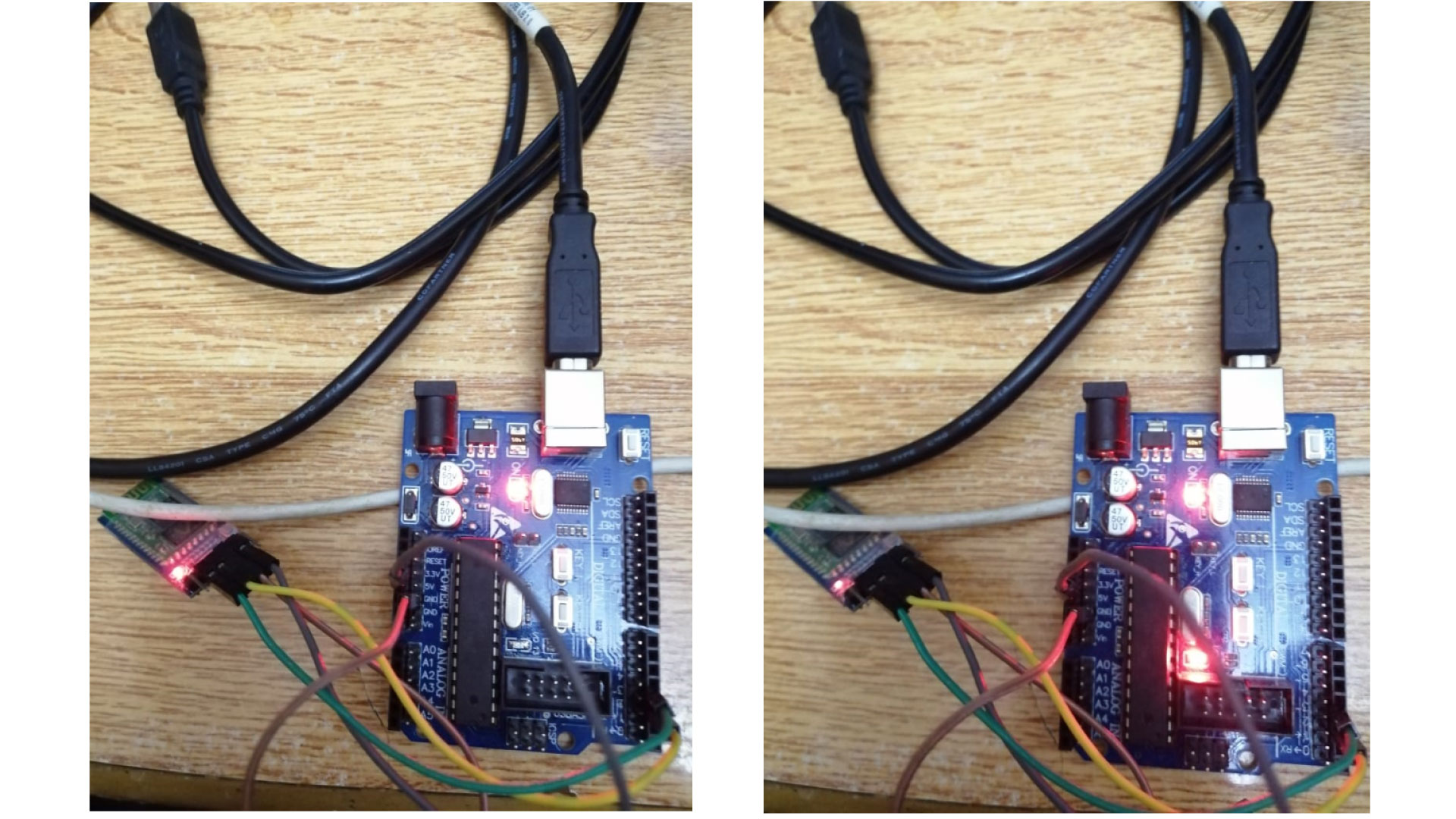
I wanted to test the HC-06 Bluetooth module to turn on the built in LED using Blynk software, I connected the bluetooth module using software serial instead of the hardware TX and RX.
-Vcc to 3.3v
-GND to GND
RX to digital pin 3
Tx to digital pin 2
Then used blynk software and created a new project.
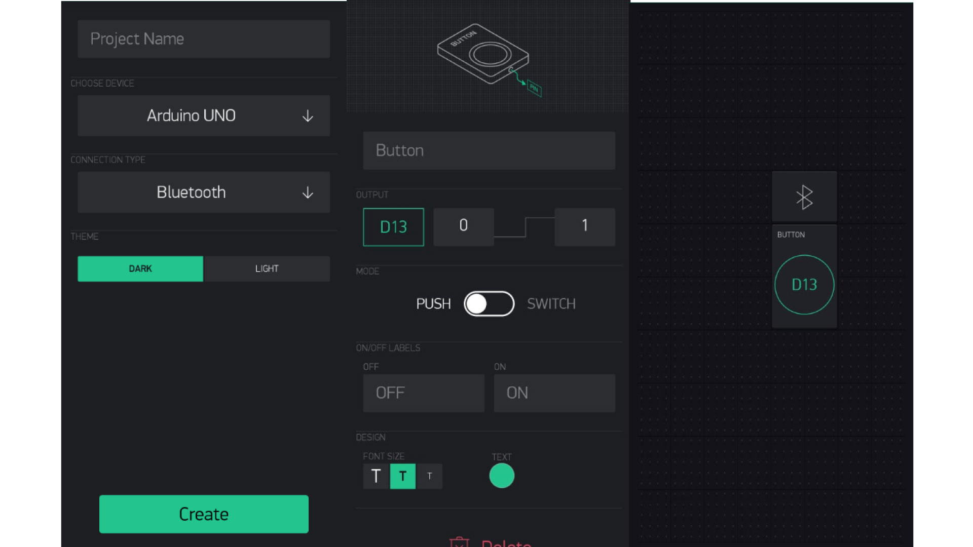
The authentication code is sent via Email, this code is needed in the arduino code below:
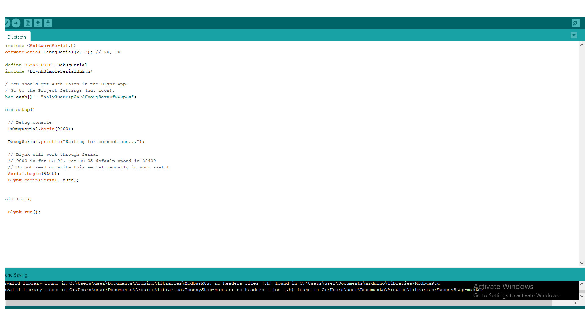
first, we need to connect to the bluetooth device, then we can press on the button on the App, the LED should turn ON.