Input devices
Assignment:
Group assignment:
- Probe an input device's analog levels and digital signals.
Individual assignment
Measure something: add a sensor to a microcontroller board that you have designed and read it.
Assignment:
Input devices like sensors or buttons are used to provide data to our microcontroller to make actions based on their readings.
For this assignment, I will be testing multiple sensors.
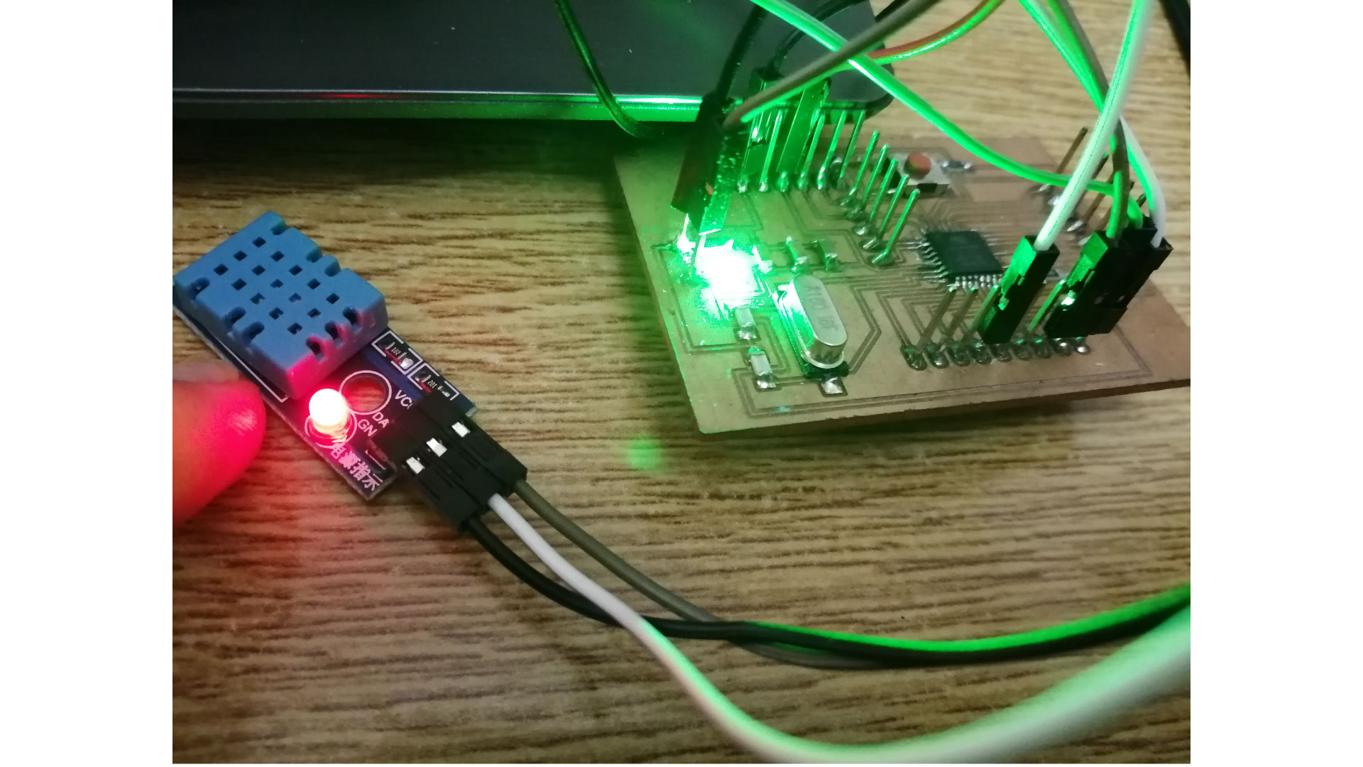
I created a board based on the Atmega328 for this assignment.
Sensors used for the assignment:
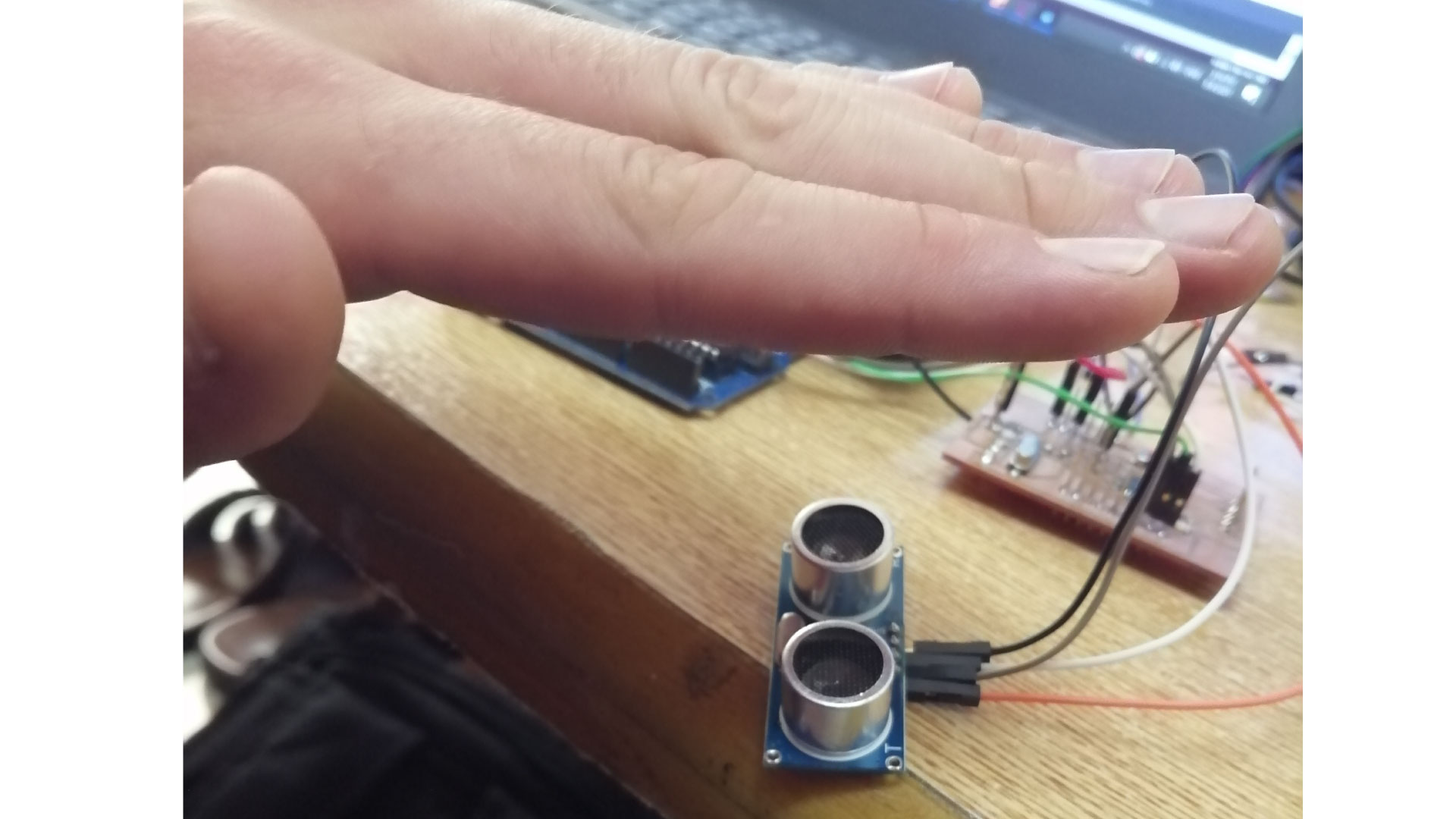
Ultrasonic sensor
Temperature and humedity sensor
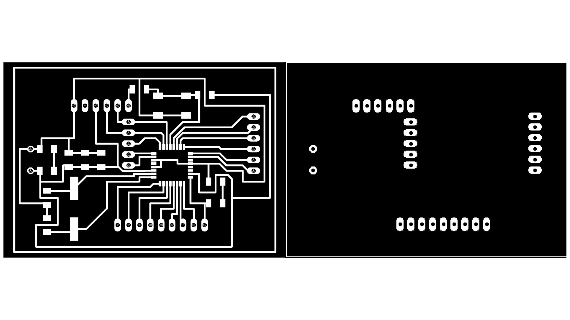
Designing The Board
I used Satshakit as a reference to design my board.
My board is based on the ATmega328 microcontroller for my board.
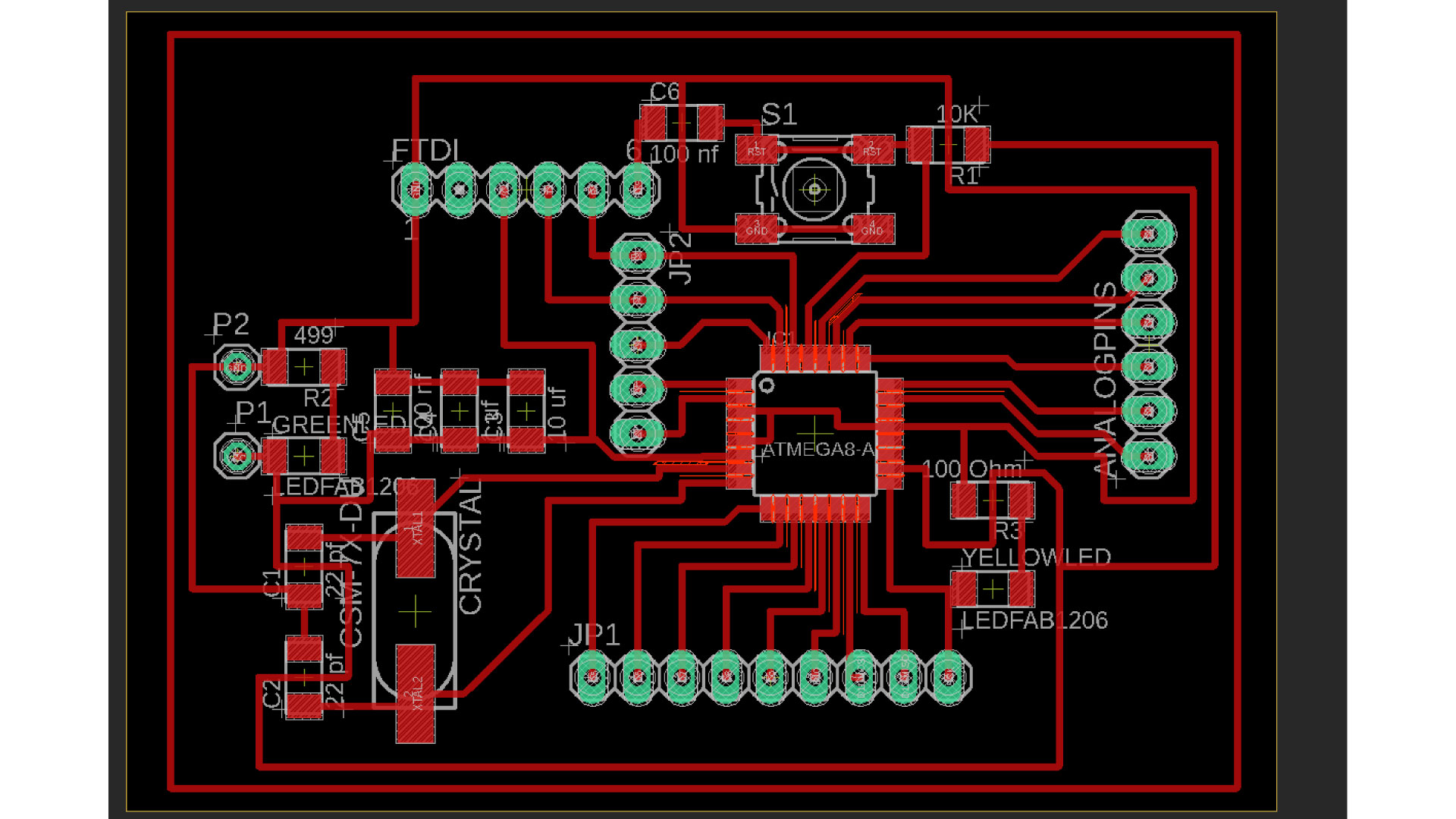
I used Autodesk Eagle to design my board and to extrude the traces for milling
Below, we can see the pinout of the microcontroller
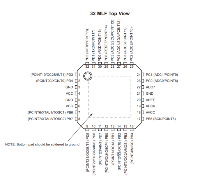
Pinout discription:
VCC: Digital supply voltage.
GND: Ground.
Port B: XTAL1 and XTAL2
Port B is an 8-bit bi-directional I/O port. As inputs, port B pins that are externally pulled low will source current if the pull-up resistors are activated. The Port B pins are tri-stated when a reset condition becomes active, even if the clock is not running.
Port C: is a 7-bit bi-directional I/O port. As inputs, Port C pins that are externally pulled low will source current if the pull-up resistors are activated. The port C pins are tri-stated when a reset condition becomes active, even if the clock is not running.
PC6: reset pin, PC6 is used as an input pin.
Port D: Port D is an 8-bit bi-directional I/O port. As inputs, port D pins that are externally pulled low will source current if the pull-up resistors are activated. The port D pins are tri-stated when a reset condition becomes active, even if the clock is not running.
AVCC: AVCC is the supply voltage pin for the A/D converter, PC3:0, and ADC7:6. It should be externally connected to VCC, even if the ADC is not used. If the ADC is used, it should be connected to VCC through a low-pass filter. Note that PC6..4 use digital supply voltage, VCC.
AREF: AREF is the analog reference pin for the A/D converter.
ADC7: ADC7:6 serve as analog inputs to the A/D converter. These pins are powered from the analog supply and serve as 10-bit ADC channels.
Eagle design
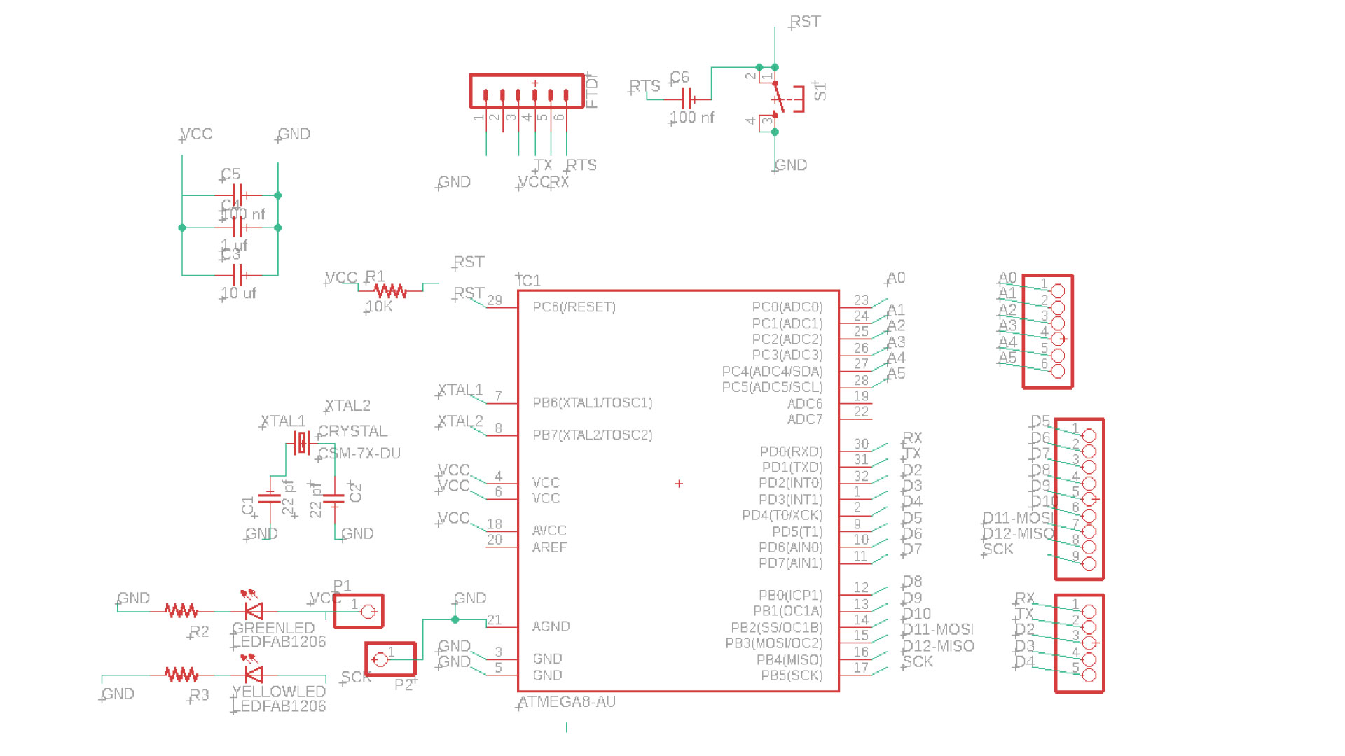
Pin4,6,18: VCC connected to the supply voltage.
Pin7-8: PB6-PB7 XTAL1-XTAL2 are connected to the crystal.
Pin 3-5-21: are connected to the ground.
Pin29: PC6 is connected to the reset.
Pin17: PB5 SCK is connected to the LED.
Pin15: PB3 MOSI digital pin.
Pin16: PB4 MISO digital pin.
Pin30: PD0 is connected to the RXD.
Pin31: PD1 is connected to the TXD.
Pin27: PC4 is analog pin connected to the SDA.
Pin28: PC5 is analog pin connected to the SCL.
A0-A7 are analog pins.
D0-D13 are digital pins.
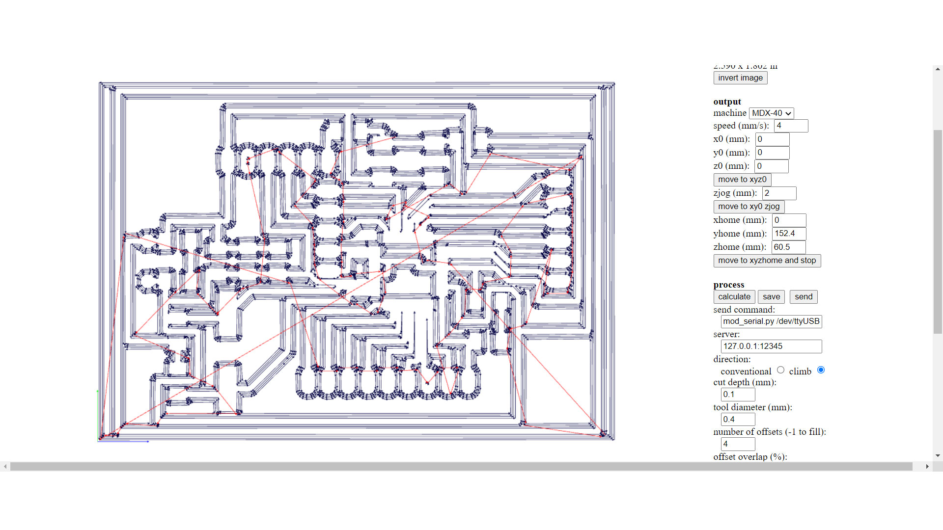
Milling the board
I used Fabmodules to generate the G-code for my board. First, I exrtacted the images for the traces, holes, and outline from eagle.
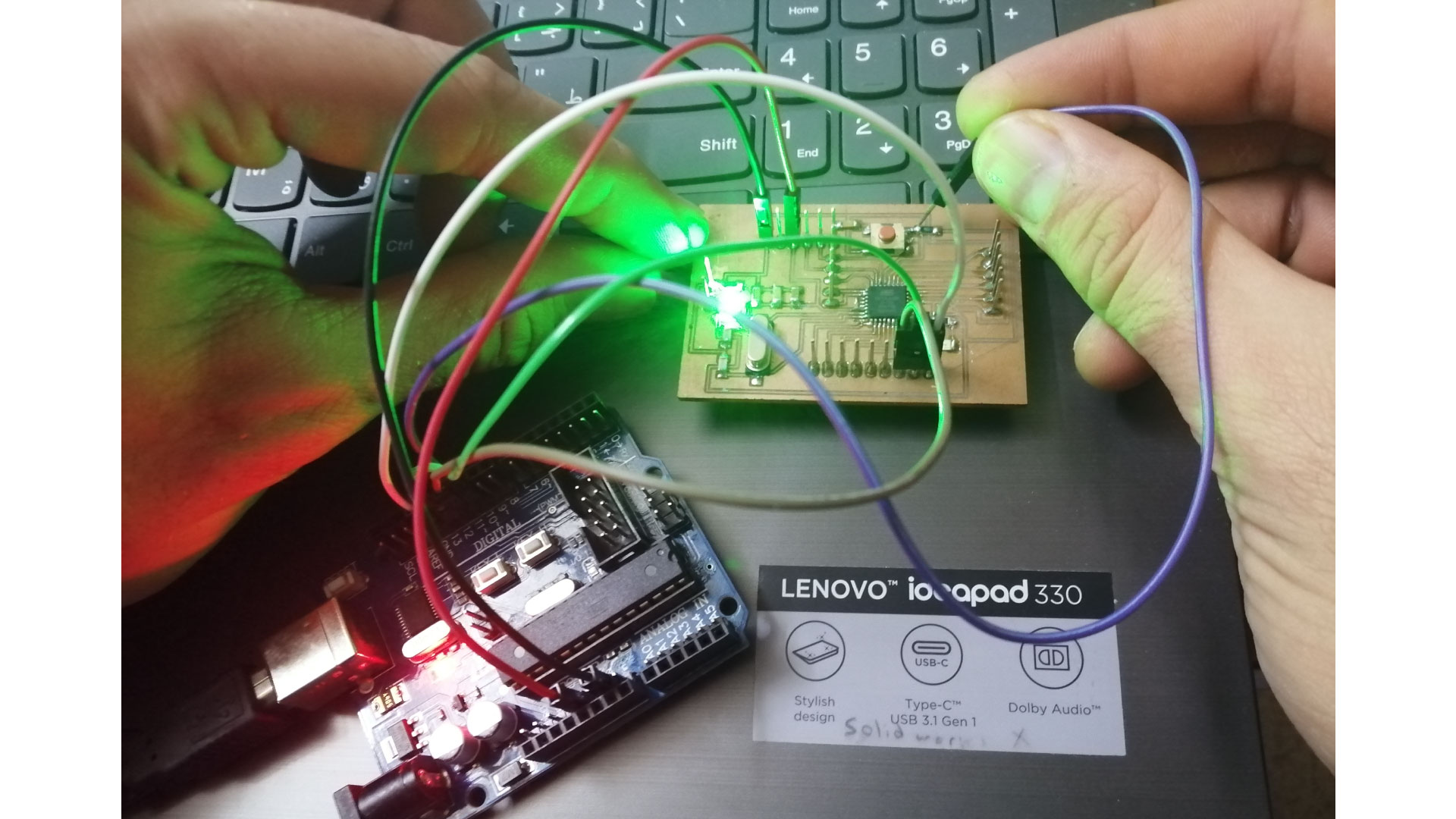
>After soldering the components on my board, I notices that I didn't include a reset pin, so while programming my board, i will have to manually place a wire on the reset line. Another thing is the TX and RX pins on the FTDI pins are flipped, so i cannot directly plug the FTDI on my board, I will be taking wires and plugging them to the pins.
Programming the board
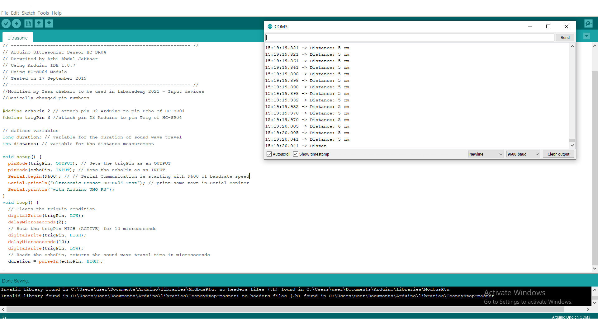
I used Arduino to program my board, using the Arduino IDE to burn the bootloader to my board.
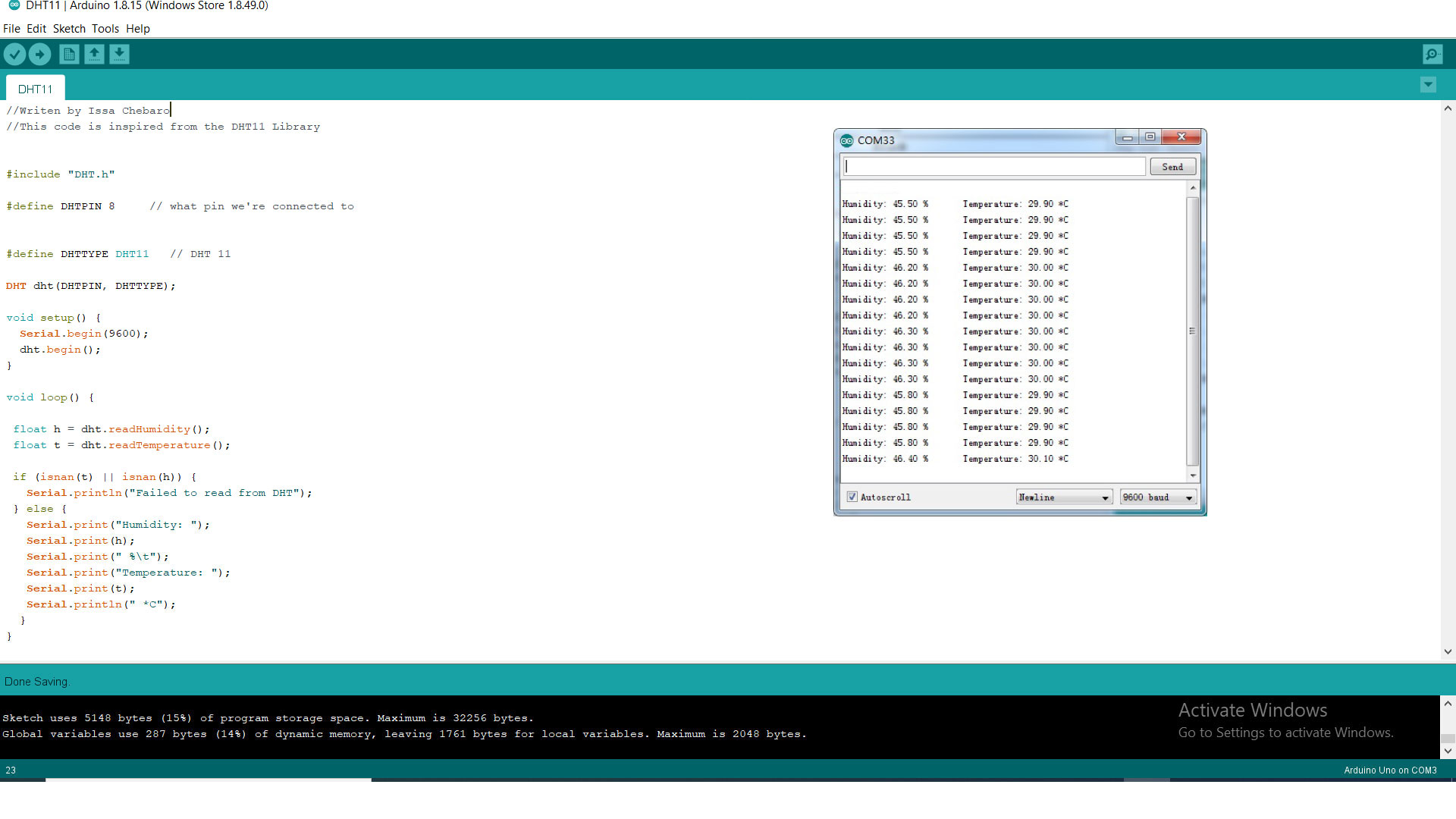
DHT11 temperature and humidity sensor
Code:
HC-SR04 ultrasonic distance sensor
Group assignment:
You can find our group assignment here.
In this group assignment we are going to read an analog input on the Tektronix TBS1052B Digital Oscilloscope.
Analog read
We connected an LDR sensor to the board with the positive probe to the LDR and the negative probe to the GND. In the video we can see the values changing on the oscilloscope screen depending on the light intensity.
Digital read
We connected a push button to the board with the positive probe to the button and the negative probe to the GND. In the video we can see the values changing on the oscilloscope screen when we click the button.
