
Outputs
OUTPUTS
This is the content we had covered this week:
- Electrical safety
- Power
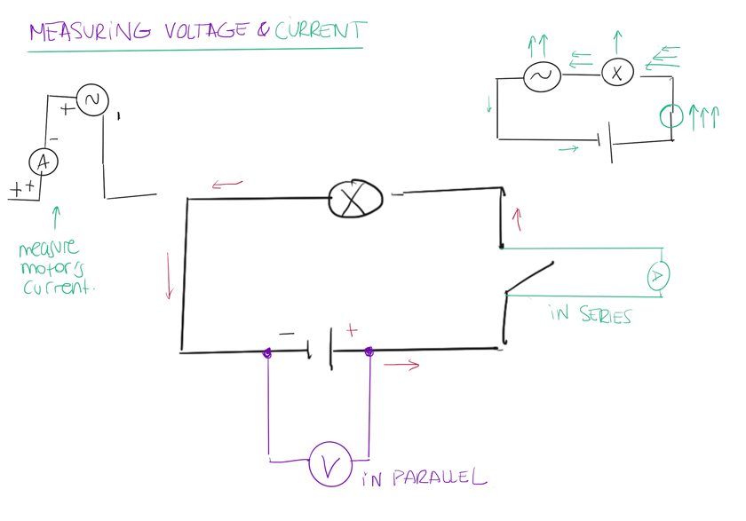
- Current Measurement
- LEDs
- Displays
- Video
- Speaker
- Motors
- …
Assignment
-
Group assignment: measure the power consumption of an output device
-
Individual assignment: add an output device to a microcontroller board you’ve designed, and program it to do something
W12 - Outputs
HOW TO USE OUTPUTS
This week we covered many outputs that I’ve already used. However, the theoretical load around some of them was way beyond what I could process without going one by one.
OUTPUTS 101
Find here my sketches with the summary for the most relevant elements this week.
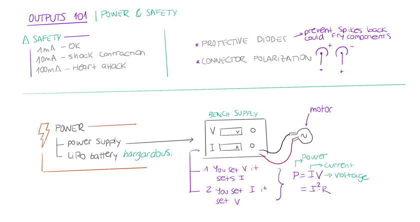
"Power & Safety Sketch."
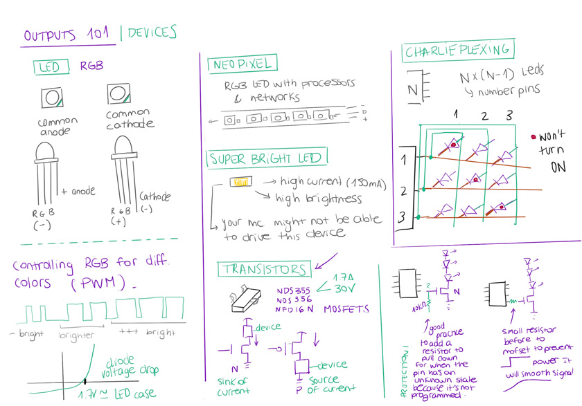
"Outputs 101 | Devices."
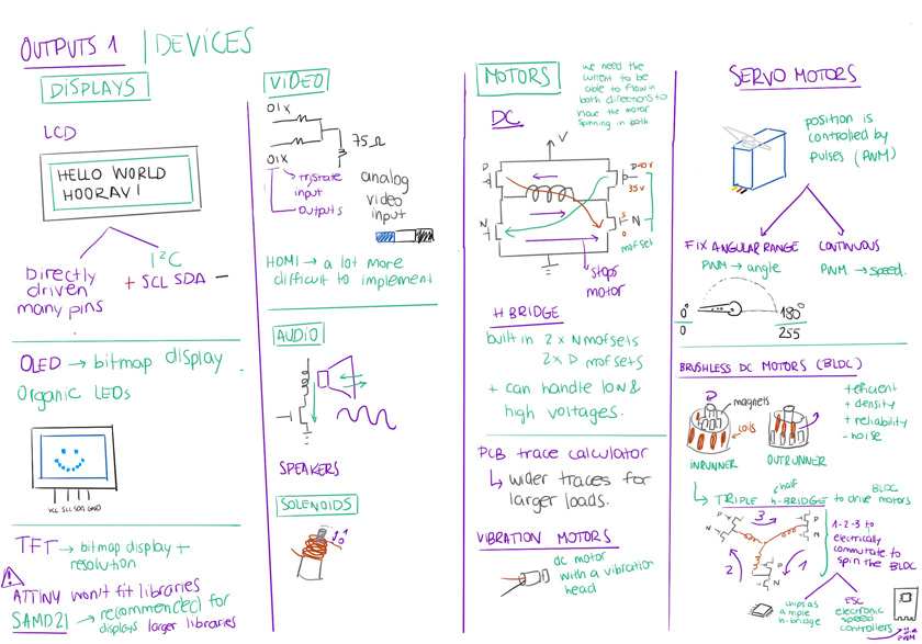
"Outputs 101 | Devices."
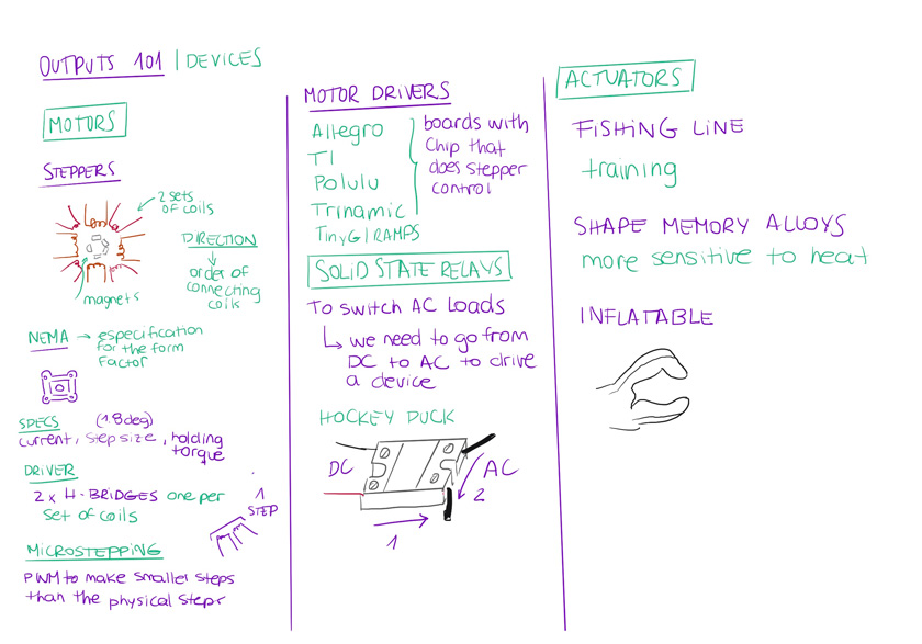
"Outputs 101 | Devices."
GROUP ASSIGNMENT
As alwats that I need to understand better a concept I did some drawings before messing up my board.
"Outputs 101 | Devices."
For the group assignment I measured the current for different types of LED with different resistors & a servo. The servo was really meaningful to see that even on hold it had some consumption. As my final project plans to have so many servos this super important.
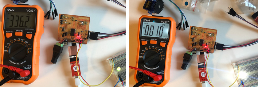
"Measuring current.LEFT: 5 mm green LED with 220 Ohm resistor. RIGHT: Super bright 3mm with 220 Ohm resistor,"
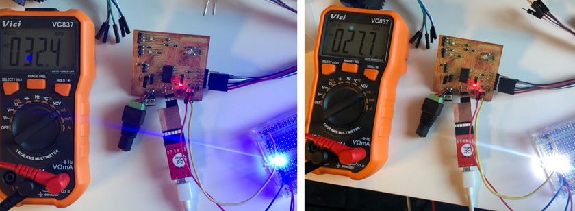
"Measuring current.LEFT: 3 mm blue LED with 220 Ohm resistor. RIGHT: Super bright 5mm with 220 Ohm resistor,"
"Checking servo's consumption while moving & on hold."
Link to Adrien’s page with the group assignment
WHAT WENT WELL
Better Understanding:The exercise was useful to incorporate something that should be part of our day to day.
WHAT COULD BE BETTER
Final project taking over:I feel that I can’t decicate that much time to the group assignment, so what we have is not as complete as we did at the very beginning.
INDIVIDUAL ASSIGNMENT
HOW TO USE OUTPUTS THAT WILL BE USEFUL FOR MY FINAL PROJECT
This week I spent a substantial time developing a lot of detail of my final project. That included considering multiple possible outputs for my phygital display. This is the proposal that I’ve developed after this week’s very useful tests.
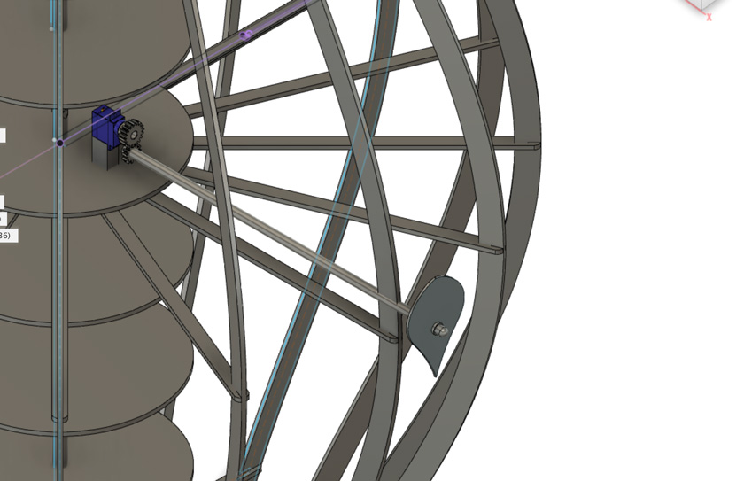
"Detail of mechanical component (WIP)."
Potentially, I’ll be using servos, but in the meantime, as the number will reach around a 100, I decided to work with RGB addressable LEDs to work around my code to show multiple states.
DESIGNING & MILLING A BOARD TO CONTROL MULTIPLE OUTPUTS
To try as many possibilities for my final project I decided to choose a microcontroller that has many PWM pins to control servos and LED dimming among others.
Find here the manufacturer’s datasheet for the ATTiny:
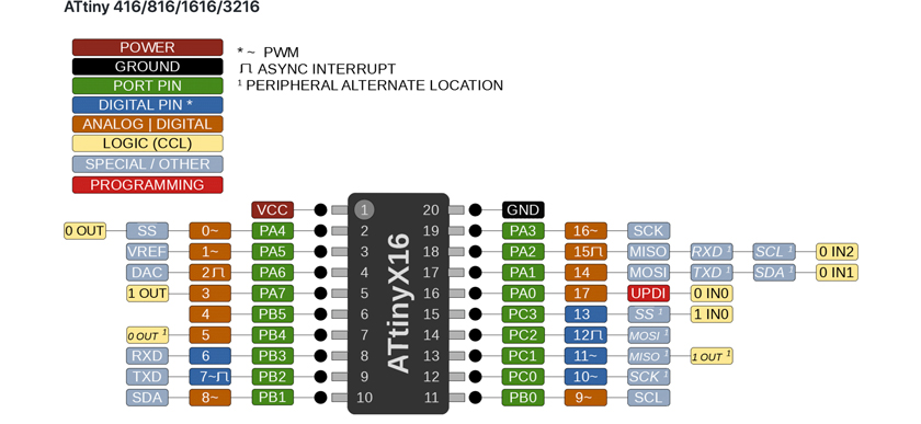
STEP 1: CHOOSE MICROCONTROLLER | ATTINY3216
As I needed to design the board which I called Tiny Outputs I had to get very familiar with this pinout.
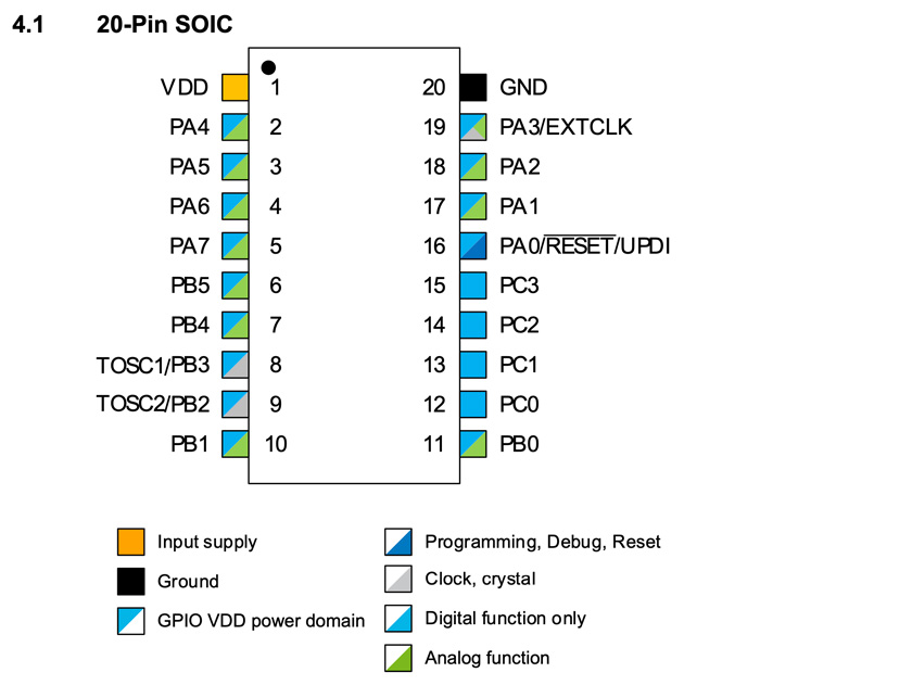
"ATTiny 3612 20-Pin SOIC"
As I’ll be testing many outputs I tried to maximize as much as I could the board.
- 2 x Servos
- LED strips
- 5V + GND pins
- 4 PWM pins
- FTDI ( Serial Connexion)
- UPDI ( Programming)
- I2C (SCL & SDA)
STEP 2: DESIGN SCHEMATIC USING KICAD
I tried to maximize as much as I could the available pins of the ATTINY 3216. The Tiny Outputs board is meant to be a test board for my final project. Therefore there’re different parts that were essential to choose the final sections later on.
Power + Power estabilization: 5v + a capacitor to ensure a stable supply of energy.
UPDI programmer connection to programm the board.
Serial pins to allow serial communication through and FTDI to debug and use the Serial Monitor as interface for some tests.
I2C pins: to connect to other boards using SCL & SDA.
2x Servo connections as is potentially going to be the output in my final project. 5V, ground and PWM.
Led Strip connection to be able to programm multiple states with light. 5V, ground and data.
Extra pins: I tried to add as many PWM pins as possible + 5V & ground to power other outpus.
Switch: I added a switch to have an inputdirectly on the board.
Some 0 ohms resistors were added as jumpers to have a cleaner layout.
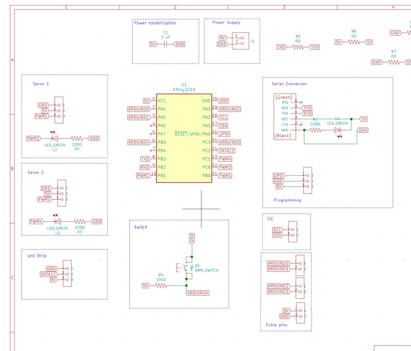
"Kicad Schematic for Tiny Outputs board"
STEP 3: DESIGN PCB’S ROUTING
This is one of the most tedious tasks to do with so many elements because of being limited to 50mmx 50mm for the CNC machine’s bed. I finally was able to arrange it in quite a usable manner.
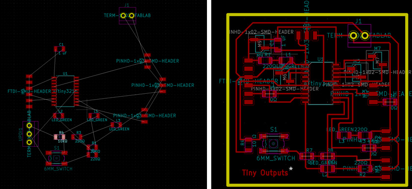
"LEFT: Pcb's components awaiting to be organized and routed. RIGHT: PCB ready to go!"
Download Kicad Pcb File, Download Kicad File, Download Kicad Net File
STEP 4: PREP FILES FOR MILLING | ILLUSTRATOR
I loaded the svg files to illustrator in layers to expand the traces and to be able to export 1000 dpi images.
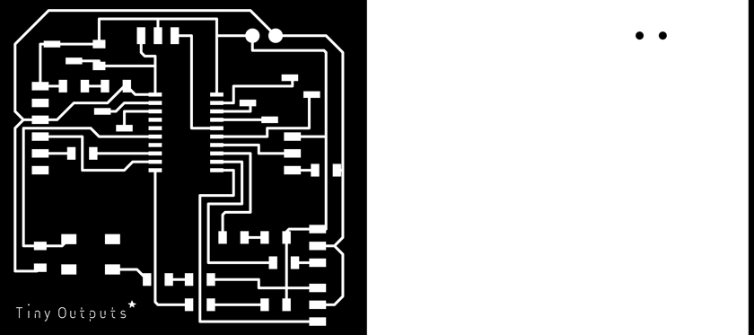
"LEFT: 1/64 Endmill File. RIGHT: 1/32 Endmill File"
Download .ai File, Download Traces 1000dpi File ,Download Cutout 1000dpi File
STEP 5: SETTING UP CANDLE CNC
I’m borrowing a windows machine for this one to make things easier. There is a special set of instructions to set up:
INSTALLING THE G-CODE CNC MACHINE ON WINDOWS
- Check on the CNC’S board for the USB controller, its a 15mm x 5mm component that says CH340C. That’s a USB-Serial controller that its used to communicate the computer and the board.
- Download drivers for the Serial-USB adapter from the manufacturer: http://www.wch-ic.com/downloads/CH341SER_ZIP.html
- Uncompress the zip to a folder.
- Run the “SETUP” file.
- Depending on your settings, you’ll need to accept some security warnings.
- Click on “Install” button: This will install the drivers.
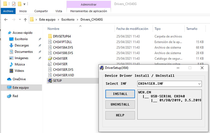
"Installing drivers.
- Plug the machine to your computer & make sure it has the power supply connected.
INSTALLING CANDLE CNC ON WINDOWS
- Go to https://github.com/Denvi/Candle
- Download the aplication. I downloaded Candle CNC for GRBL firmware 1.1, –> Windows: candle_1.1.7.zip
- Uncompress the zip file to a folder.
- Run the “CANDLE” file.
- First time you open the applciation you need to set up the COM port the machine is exposed on.
- Go to “Service” -> “Options” (“Servicio” -> “Opciones”)
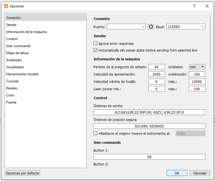
"Installing drivers".
- On the “Connection” Section select the COM port your machine is on.
SET UP X-Y AXIS & Z & LOAD FILE
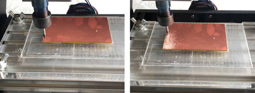
As usual I added double-sided tape in the back and aligned the copper board on the lower left corner of the machine. Setting Z axis was trickier than with the Roland machine.
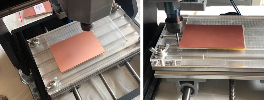
"Homing Machine".
With Candle’s CNC interface it was quite easy to launch the file and even pause it two times when I realized that the z axis wasn’t properly aligned with the bed.
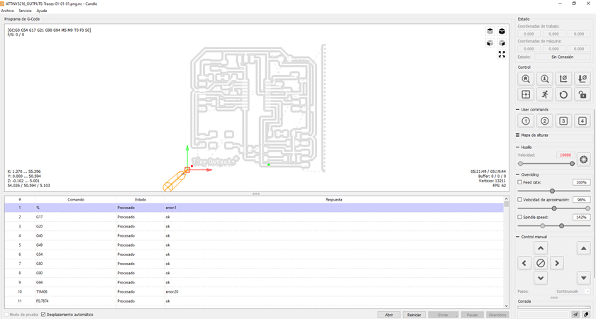
"Loading File & Following progress".
STEP 5: MILLING FOREVER TIME
Oh boy, didn’t I know that it was going to take long, but not sooooooo long. Two attempts where the endmill wasn’t cutting all the traces didn’t help.
"LEFT: First attempt failed to cut through. RIGHT: Milling on going!".
"Cnc Milling going as expected."
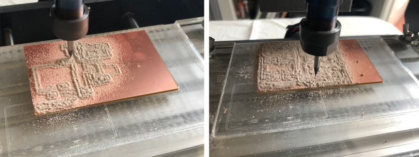
"LEFT: About 3h after. RIGHT: Almost about to finish, around 6h after".
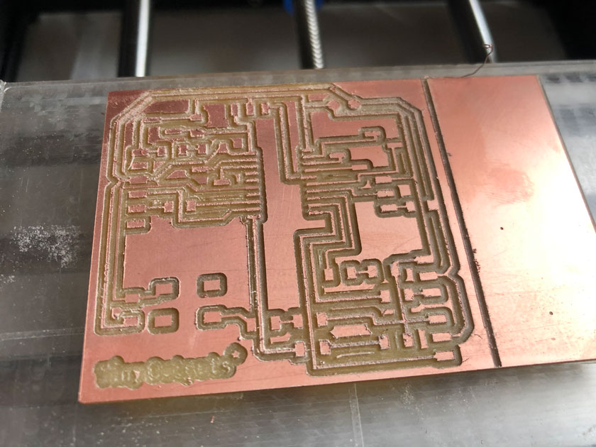
"Finished milled Tiny Outputs."
All in all, the board turned out decently. It took a lot more than it should have with the Roland, but in the end it allowed me to win some time.
USING AN ARDUINO BOARD TO TEST ALL THE OUTPUTS I WANT TO USE
As the milling took a lot of time, I decided to test all the outputs I wanted to use using and Arduino Leonardo board I had at hand.
STEP 1: LEDS
Starting simple, blinking LEDs to ensure that the board works. I plan on using this code with the milled board to check all the workflow. Keeping it simple.
Download Arduino Blinking Built in Led File
STEP 2: NEOPIXELS
Neopixels are always a treat. As it’s been a while I checked the documentation from Adafruit’s website that it’s very clear
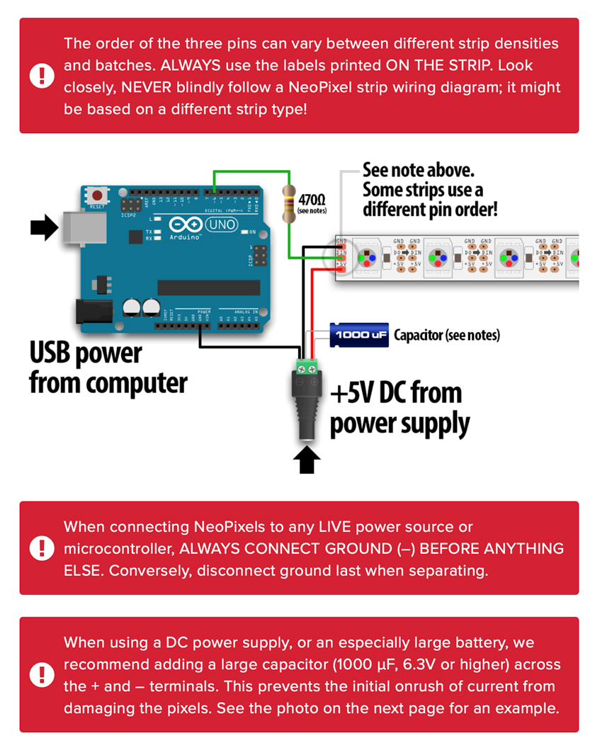
"Neopixels Wiring & Warnings"
Neopixel Library Reference Neopixel Library Repo
"Programming Neopixels to a 4 color sequence."
Download Arduino Neopixels File
STEP 3: SERVO
Servo’s wiring is always that I always need to check out. So here a reminder for my future self.
"Servo Wiring"
I always check the requirements and as I’ll be using servos for quite a bit it will be handy for sure.
As some servos fail, testing it with a basic sweep.
"Servo Sweep."
Download Arduino Sweep Servo File
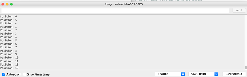
I’m trying to have 4 positions, and even the 180ª can’t provide four 90º angles, I’m checking the code for 45º.
"Servo motor 4 positions."
Download Arduino 4 positions Servo File
This last bit looks very promising. I need to figure out something to change the range of the angle but it seems quite accurate.
STEP 4: CONTINUOUS SERVO
The continuous servo seemed a good option as it can give me the 360º range and beyond.
As I’ve never used one I looked up some information in which I learned that it works as a dc motor and when using the servo library, you don’t define the angle rather than the speed the servo moves either back and forth.
"Continuous Servo controlled pulses."
"Continuous Servo aiming for 90º turns using millis."
Download Arduino continuous servo File
For my purpose, I believe I had some problems with its accuracy. I looked it up in case I was doing something wrong, but as it turns out it’s not just me.
STEP 5: ROTARY ENCODER
On an attempt on getting closer on accuracy, I wanted to map a rotary encoder to the servo’s movement.
"Rotary Encoder."
Download Arduino rotary encoder File
STEP 6: CONTINUOUS SERVO + ROTARY ENCODER
This is the last attempt on trying to control the continous servo at a will. After this I decided to go with the regular servo.
"Rotary Encoder."
Download Arduino continuous servo + Rotary encoder File
STEP 7: DISCARDING OTHER OPTIONS
Originally I had the idea of using the tiny stepper motors because both functionally and aesthetically would be perfect. However needing so many motor drivers and a lot of power I decided to discard it.
WHAT WENT WELL
Clear Picture: By testing all the available options I was able to define a path towards next steps.
WHAT COULD BE BETTER
Not ideal: I’m not a fun of the blue clear servos for my project as I want the electronics to be visible..
USING AN ATTINY 3216 CUSTOM BOARD
But first, I need to assemble it. Good look Carla!
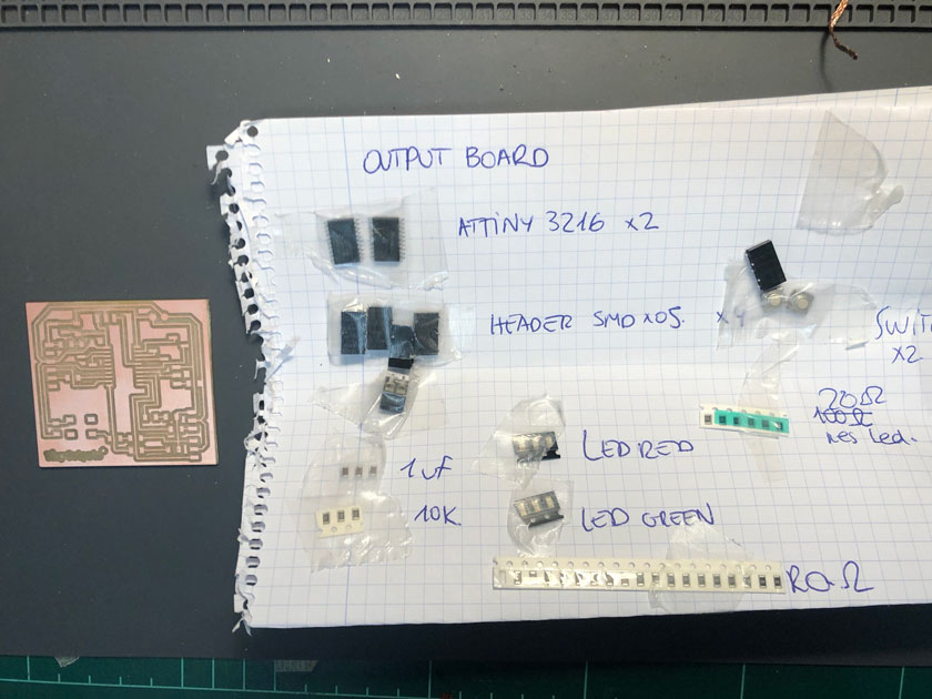
"Tiny Outputs board with all the SMD components ready to be soldered."
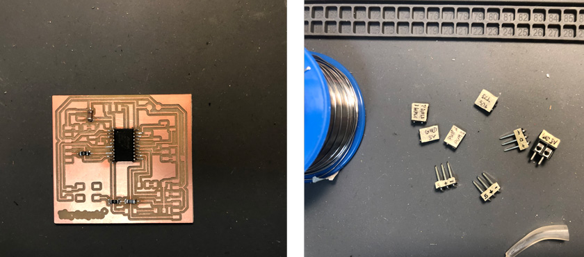
"LEFT: ATTiny 3216 soldered. RIGHT: Labeling header sockets."
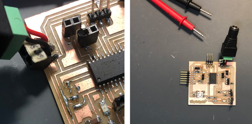
"LEFT: Sadly, the UPDI broke just when plugging it... RIGHT: Fixer upper board!"
STEP 0: UPDI + FTDI BATTLE
At every step this pinout diagram from the Mega Tiny Core Repo is key to see the number of the pins for the Arduino IDE.
"3216 for Arduino IDE + Mega Tiny Core Pinout (in Orange & Blue)"
Link to Attiny 3216 Pinout for Arduino IDE + Mega Tiny Core
Why was it a battle. Because after the UPDI broke and I had to fix it. I discovered that the FTDI connected nexto to the UPDI wasn’t working properly so uploading the code didn’t work. When using another one, magic happened.
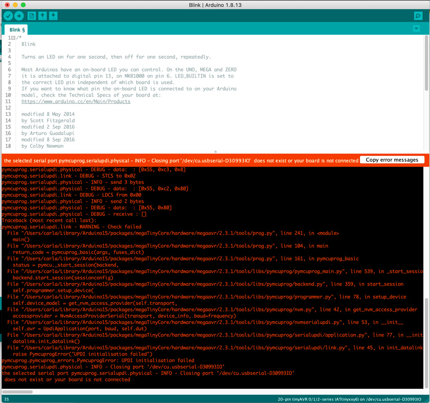
"Error shown when uploading code with the faulty FTDI."
So after using a new FTDI for the UPDI connexion I decided to connect the FTDI for the serial monitor at the same time. Needless to say that on my Mac machine with usb-c it doesn’t work at all times.
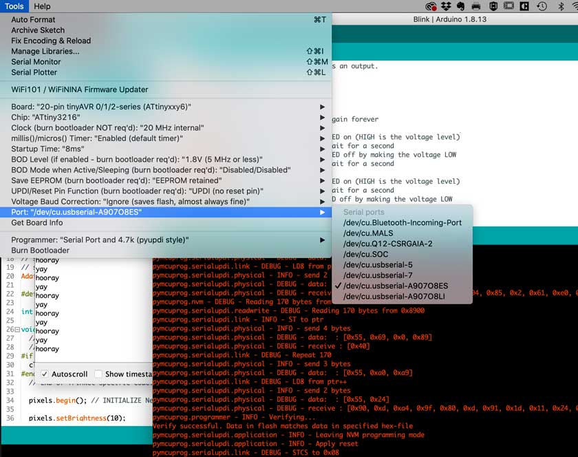
"Image showing to serial devices (UPDI + FTDI)"
Spence Konde’s Mega Tiny Core is the way to go with any issue.
Problem with Uploading the code
And finally, the moment I was waiting for veeeeery long! Tadaaah!
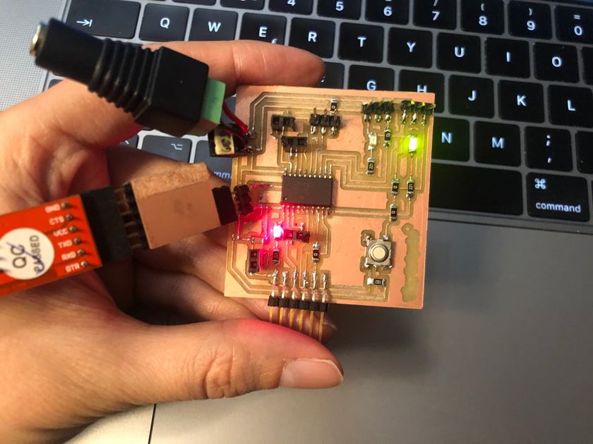
"Tiny Outputs Board working after some hiccups."
"First Led blinking on the 3216 board, quite a magical moment of relief."
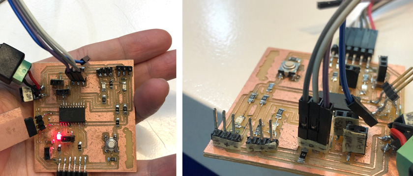
"LEFT: Top view Board. RIGHT: Side view board with labels."
STEP 1: LEDS
So, as with the Arduino board, I start simple and build on complexity.
I added a green and red LED to the board to troubleshoot. And for my relief, it worked as well.
"Red and Green SMD leds programmed to blink."
I wanted to test the Serial connexion so I used the FTDI to send a message (yay) and respond (hooray).
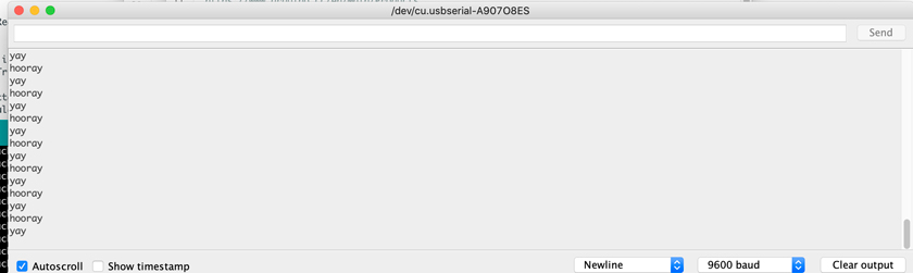
"Screen showing the Serial Monitor of the ATTINY 3216."
"Serial Monitor in action."
Download Attiny 3216 Blinking Leds File + Serial
So far so good, let’s try all the other outputs.
STEP 2: NEOPIXELS
When I tried to compile the code, I got an error.
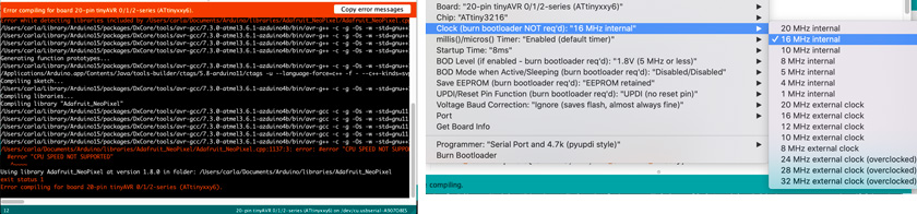
"LEFT: Error CPU speed message. RIGHT: New clock setting to match library's speed."
After deciphering the error message I changed the code from 20 Mhz to 16Mhz. After a bit I decided to test the neopixels + button to change the colors.
"Neopixel changing colors when pressing a button with the ATTiny3216."
Download ATTiny 3216 Neopixel 4 colors code
STEP 3: SERVO
Today it seems the day of libraries’ problems. Apparently I had a servo library installed that it’s not compatible with the ATTiny 3216. After removing it, everything worked.
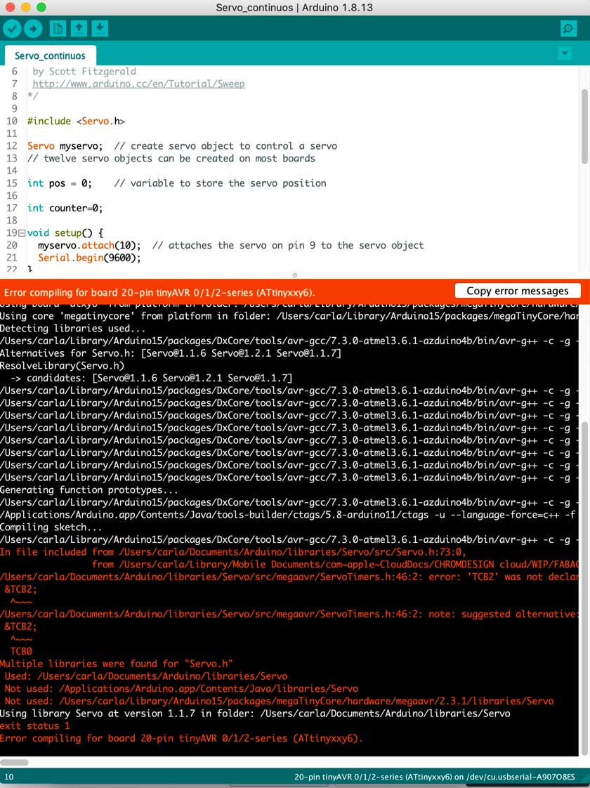
"Error message from the incompatible servo library."
Some useful help I got from here:
Link Troubleshooting Servo libraries problem
"Servo 4 positions, 0º, 45º, 90º,135ª with ATTiny 3216."
Download ATTiny 3216 servo 4 positions code
Servo went according to plan, and it seems that for now, it’s the strongest contender.
STEP 4: CONTINUOUS SERVO
With this servo, I’m trying the other PWM servo connection.Aaaaand it works!
"Continouos servo with the ATTIny 3216."
Download ATTiny 3216 continuous servo code
STEP 5: ROTARY ENCODER
Lastly I wanted to try other headers with an input, so I plugged the rotary encoder in.
"Screenshot from the Serial Monitor showing the value of the rotary encoder."
"Rotary Encoder + FTDI showing a blink at every turn of the knob."
STEP 6: CONTINUOUS SERVO + ROTARY ENCODER
Lastly, I adapted the code for the ATTINY 3216 to work with the rotary encoder and the continuous servo.
"Rotary Encoder + continuous servo changes direction when turning the knob."
Download ATTiny 3216 rotary encoder + continuous servo code
FINAL STEP: START ENCODING GENETIC CODE
I tried to work on a small chunk of the system that my final project will have, that is the program that will encode the genetic code and transform it into the phygital display.
For this test I’m using the Serial to read Keyboard Input ( letters A,T,C,G) and transform it into a different color each letter.
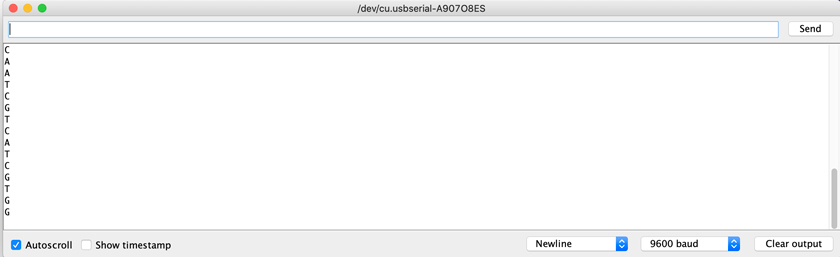
"Screenshot showing the genetic code letters coming from the Keyboard as an input."
"Serial Sending Genetic code to one Neopixel"
For the second iteration I tried to do the same encoding but on a sequence of LEDs.
"Serial Sending Genetic code to multiple Neopixels"
Download ATTiny 3216 NeoPixel + Serial Monitor
Reference Keyboard Input to Arduino –> Domain not available anymore, you’ll go to a Wayback Machine capture.
HERO SHOT
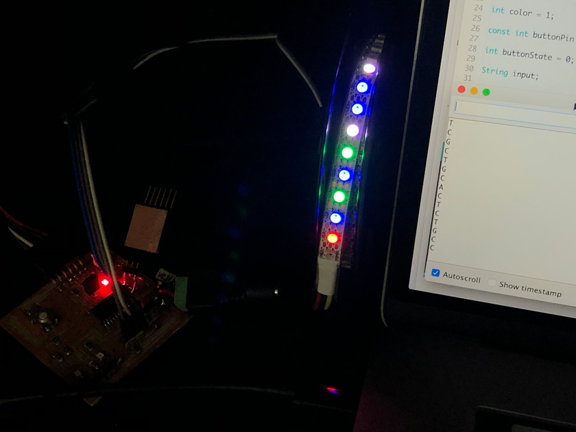
"Tiny Outputs Board connected through FTDI receiving Keyboard input thorugh Serial to change Neopixel colors."
WHAT WENT WELL
It worked: I was quite relieved that once I had the setup working it worked with all the outputs that I had already .
I learned a lot: It was a steep learning curve, but in the end it was rewarding.
WHAT COULD BE BETTER
Tricky setup again:When working with experimental soft circuits there are so many things that can go wrong.
I need a new circuit: As the UPDI connexion was so britle I had another incident. I should mill another one, but I’m waiting to add some more improvements as this one still works.
"The cable gamble."