8. Computer controlled machining
At this time I already knew the way to generate a Gcode in MODS. But this week we were assisted to use ArtCam, a GCode generating software. I had already work with ArtCam because of my work and a previous CNC machining course I assisted to.
Group Assignment
Test runout, alignment, speeds, feeds, and toolpaths for your machine
Machine:CNC Router 1325 in the Fab Lab ZOI, bed size 1220 x 2440 mm.
CNC RULES to use LINK 1. Do not leave the room while it is on, at least one person should be in the room at all times observing the machine when it is running.
-
Do not put your hand or any other part of your body any closer than 6 inches to the bit when it is moving. The router will not stop and can cause severe damage.
-
If the bit breaks or something seems to be broken or misbehaving, hit the pause button on the computer screen. If it needs to be shut off immediately press the red emergency stop button on the front of the bed.
-
Make sure no screws are on the path of the router. The screw will break the bit and will normally stay embedded into the project, but is capable of flying off and hitting someone.
-
After use of the machine clean the floor and all of your excess material out of the room, the sawdust on the floor and scraps can be hazardous and cause an injury.
-
Leave the CNC room clean and the way it was when you began your project. The CNC tech is not responsible for cleaning.
-
Check and empty the vacuum bag frequently. When you are complete with your project empty the vacuum. The CNC tech is not responsible for emptying.
-
Use hearing protection while the CNC is running.
-
Wear protective safety glasses when the CNC is running.
-
Do not disconnect the main vacuum line of the CNC if you wish to clean excess dust off of the work. Instead, use the smaller portable vacuum in the shop.
-
There will be no milling or machining between the hours of 11 p.m. and 8 a.m. Just like working in the shop with other power tools, you need to be rested and focused on the CNC process.

Guide to use the CNC router machine LINK
a) Activate the ignition switch b) We turn on the computer that controls the CNC

c) We turn on the CNC, green button d) Verify that the cooling pump is working.

e) Turn on the extractor f) The CNC does not save the zero position in a memory, so you have to reconfigure the zero of the machine.

g) We open the Linux CNC software and move the machine, with the arrow keys we can move to the right, left, forward, back and with the keys (repag) up and (avpag) down, in this way we control the axes x , and and z.
Parametrical design - Fusion 360
I wanted to reforce my parametrical design skills so I used fusion360 for design a shelf for my room. It had to be adapted to a wood handrail.

I started by designing the path I wanted to cut, without specific dimensions.

After I maked the constraints to have the dimentions I wanted.

The same for the two other pieces.
Then I Make a Dogbone fillet. Designing dogbones parametrically was one of the hardest things of this design process. The second one was to align joint sections, “female” parts with “male” parts.

Finally I played a litle with circles and tangent constrains to make a nicer shape.

Dogbones
To make a Dogbone fillet in fusion 360:
- create a rectangle without specifical dimentions.
- Create a circle in each corner following this Dogbone design tutorial.


- clean all excess geometry.


- make a radius constraint between the arcs to one of them.
- make an equal constraint between parallel lines.
- make a collinear constraint between the 3 point (center of the arc and limit points) in each one of the 4 arcs.
- design a horizontal and a vertical line to define the dimentions of the rectangle between two points of simetrical arcs.
- make a constraint horizontal and vertical between the points of each of those two lines.
- Sketch Dimention for each one of those two lines.
- erase the lines
- Introduce dimentions

I saved the file in .dxf and .dwg to open it in Rhinoceros to copy one of the pieces 3 times. I found it will be faster because I don’t dominate Fusion 360 yet.

GCode generation in Artcam
After I saved it in a dxf file to prepare the toolpath in Artcam.

When create a new model in artcam we have to set the work-zone with the dimentions of the material we will work with.

First I maked a single toolpath for the whole.
![]()


After I realised I needed bridges for large and small pieces so I make 2 new toolpaths separating the holes group from the pieces. I set the toolpath with the same values of the previous toolpath with the exception of the profile option.
Settings
Profile Side

- Holes’ group is checked with Inside
- Pieces’ group is checked with Outside
Finish depth

Profiling Tool

Material

Updating bridges

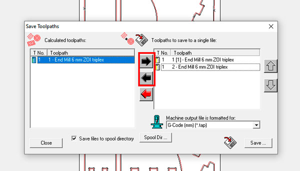
Finally i had 3 toolpath but I want to generate only one GCode mixing the pieces’ toolpath with the holes one.

I proceed to generate the GCode with checking the toolpaths I need.

Files
Fabrication
I’ll use a 15mm MDF board for my cutting so first I fixed it on the machine’s table.

Loaded the Gcode.

I put Z on zero. Here did not put Y and X axis on zero so I an error appeared.

I corrected and it worked

After that I started the first 2 GCode’s steps with the arrow button until the spidle reach a constant speed. Finally I run the whole code with the Pause button.
After sanding the bridges I tested the joints. The first was ok but it fitted very hard. The second and the third were shifted for a design error, so I sanded the parts were not fitting and finally I reach make them fit with a hammer. Joint number 4 was as well and hard to fit as the first one.

The joining process was really satisfying.

HERO SHOT

Learning outcomes
- [x] Demonstrate 2D design development for CNC production
- [x] Describe workflows for CNC production
Have you?
- [x] Linked to the group assignment page
- [x] Documented how you designed your object (something big)
- [x] Documented how you made your CAM-toolpath
- [x] Documented how you made something BIG (setting up the machine, using fixings, testing joints, adjusting feeds and speeds, depth of cut etc.)
- [x] Described problems and how you fixed them
- [x] Included your design files and ‘hero shot’ photos of final object