5. Electronics production
This week, we will learn to make PCB boards. I don’t know anything about electronics, but Henk said this is ok— we only need to follow instructions closely this week, it is more about learning the process of production than how to use electronics. We all made the FabTiny Brian ISP, which is described below. We started with a tutorial on the small milling machine.
Using the Small Milling Machine
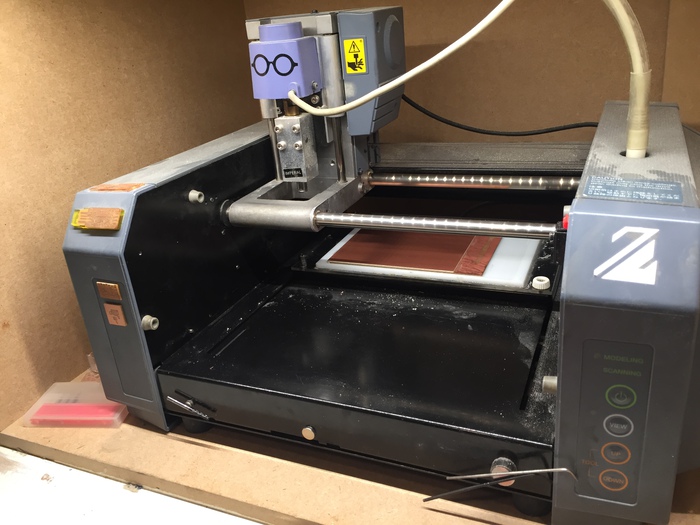
Our machine is a Roland MDX 20.
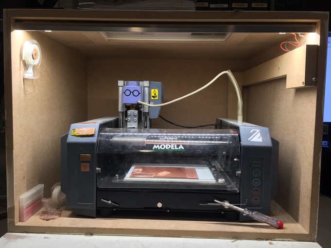
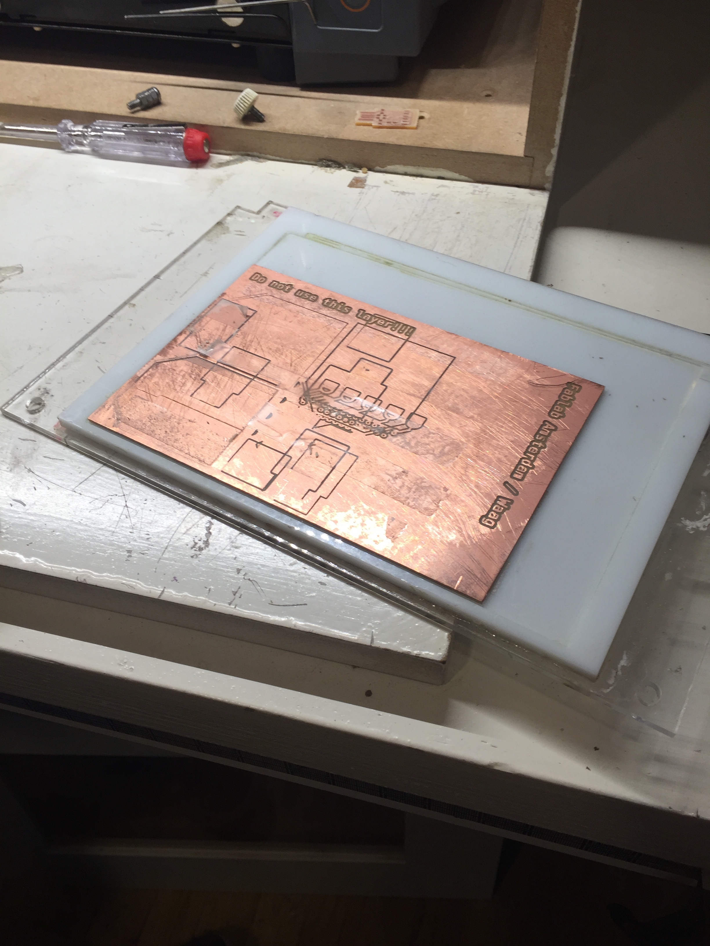
Although it can be used to mill molds or other small objects, we only use it for PCB boards in our lab. These are milled on a copper plate with a .1mm layer of copper on top. The boards here are FR1 boards, which means that they have a backing of paper phenol.
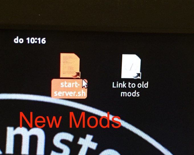
To send prints, we use Mods on the computer next to the mill.
- To open the current version, click on the “start-server.sh” icon on the desktop.
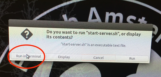
- Select “run in terminal” in the window that pops up.
- This will open both terminal and firefox Terminal will display that it is opening terminals in different ports. The ports are boards attaching to different devices. We are only usijg the device server today. This information typically will not need to be engaged with directly to mill. After Mods is started, the machine turns on and goes to its starting place. It is attached to a device called ttyUSB
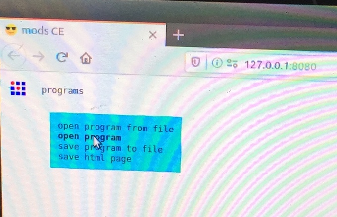
- In firefox, click on Menu > Programs > Open Program
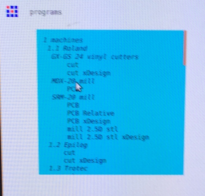
- In the list of machines, click on PCB under the MDX 20
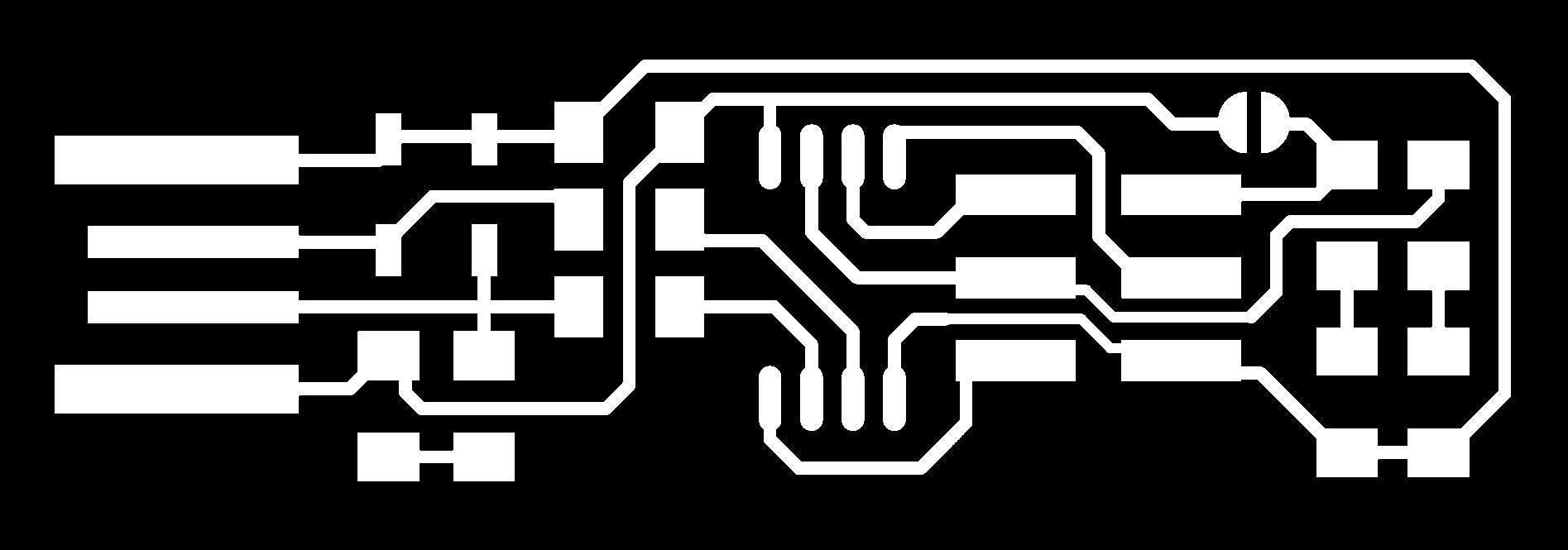
- Within mods, you can start by opening an SVG or PNG in one of the two first modules. Click on “select File” within one of these to open your file
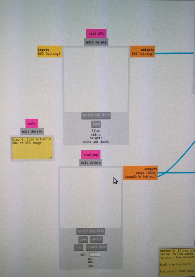
- We store these in the folder “Fablab 2020.” The white area of the image should be where we want there to be copper.
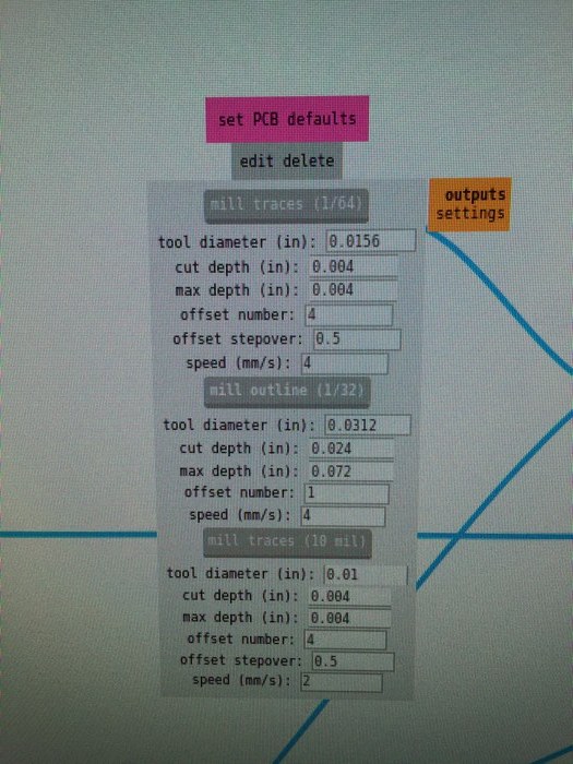
- Go to the Settings module that feeds into the Mill Raster 2D module and select either mill traces 1/64 or mill outline
The settings module has 3 categories: Mill traces 1/64, Mill outline 1/32, and Mill traces 10. We will choose from only the first two. These commands will send a set of default settings to the Mill raster 2D module.
- In the Mill raster 2D module, set the offset. This number determines the number of traces the machine will make around the perimeter of the copper in your design. We are setting offset to 4 for the tutorial.
- Stepover sets the distance between lines, set as .5 so that there is overlay between the traces, ensuring there is no leftover copper. 1 would set the distance between each new trace to the same as the diameter of the trace.
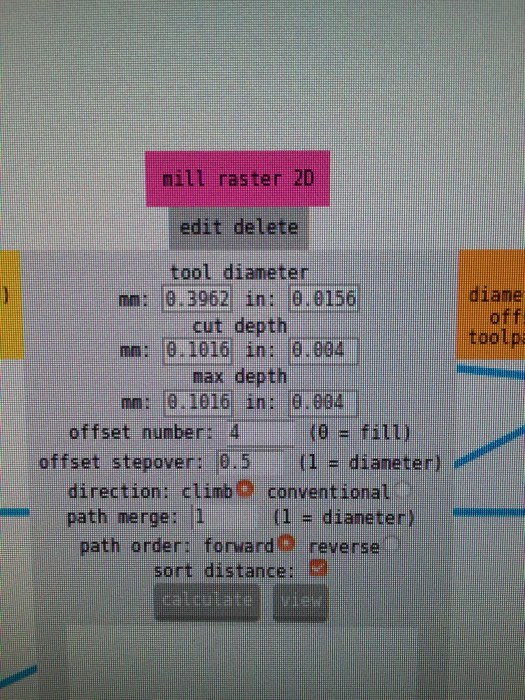
- Direction allows us to choose between climb and conventional. We typically use climb.
- Leave Path merge at 1.
- Set Path order to forward.
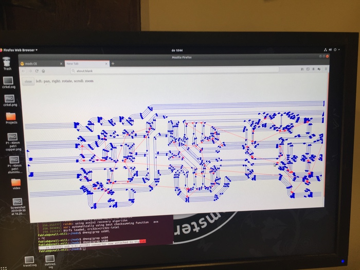
- Hit calculate to generate the path/ g code that the machine will use. Hit view a new tab will open showing the toolpath. Clicking view in the View toolpath mod will also show you the path that the machine will take.
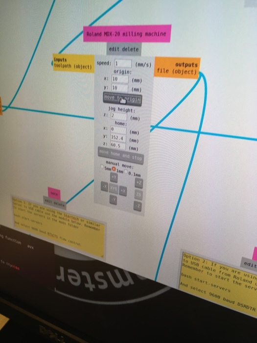
- In the Roland MDX 20 milling machine mod, you can change machine settings.
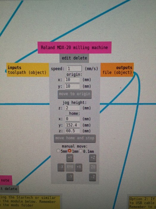
- Set speed to 1.
- Go to Websocket serial mod. We use this mod because we use a serial to USB cable at Waag. See that socket is Open. If not, click on open. This means it is connected to the device.
- From the Websocket serial mod, Click send file.
- Now go to the machine. We will return to mods to set origin.
Setting up the Machine
- Have the machine in view
- Unscrew the base.
The base is made of an acrylic bed with a sacrifical copper board attached.
- Check if there is any tape left on the sacrificial board as it affects the depth of the cut, so it must be completely removed.
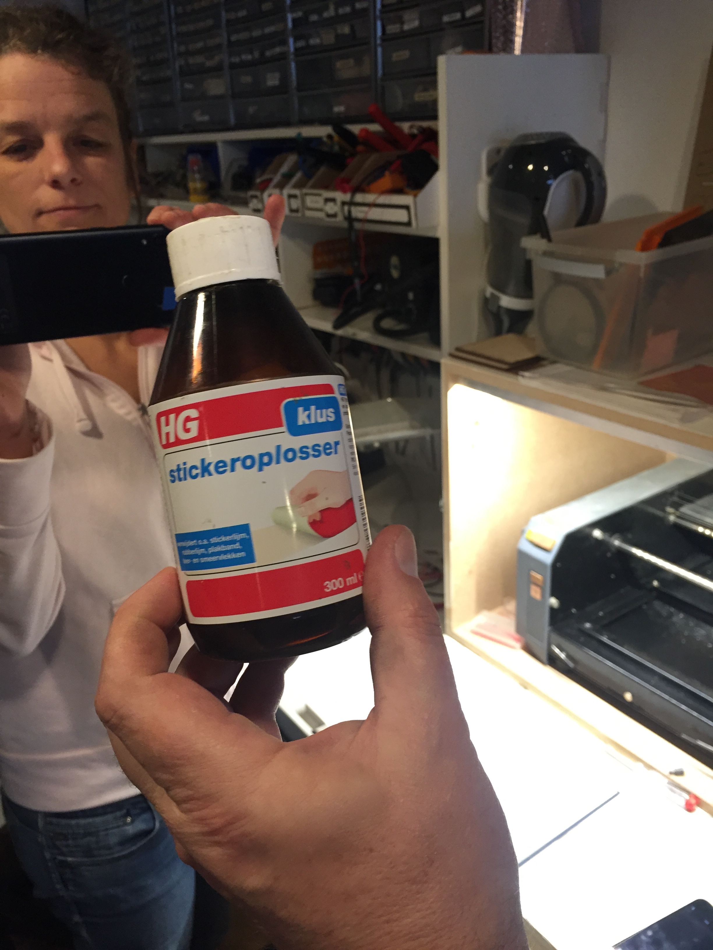
- Remove tape first with the metal scraper, then with solvent, which will be above the machine. Wipe off any paper dust with your hand.
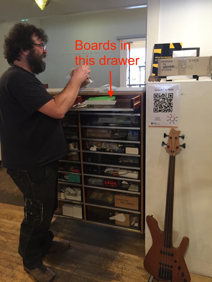
- Get a new board from the drawer.
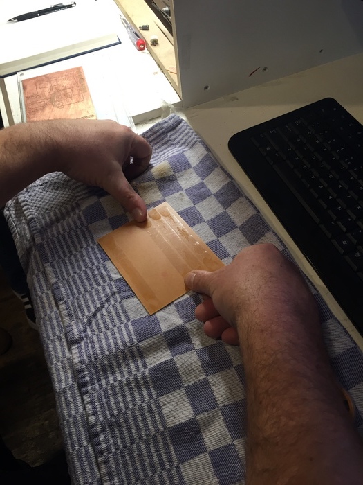
- place it face down on a towel and apply double sided tape to the entire back of the board (6 stripes)
- Place it exactly on the corner of sacrifical material, then put the whole base face down on the towel and use force to make sure the board is stuck.
- Screw the plate back in
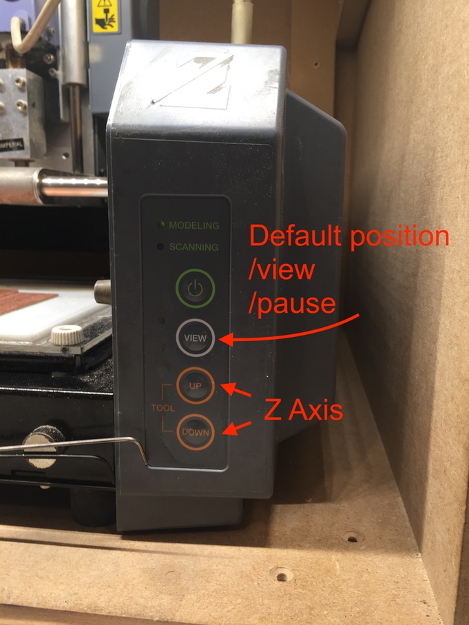
- press view to exit view mode, it will travel to starting position
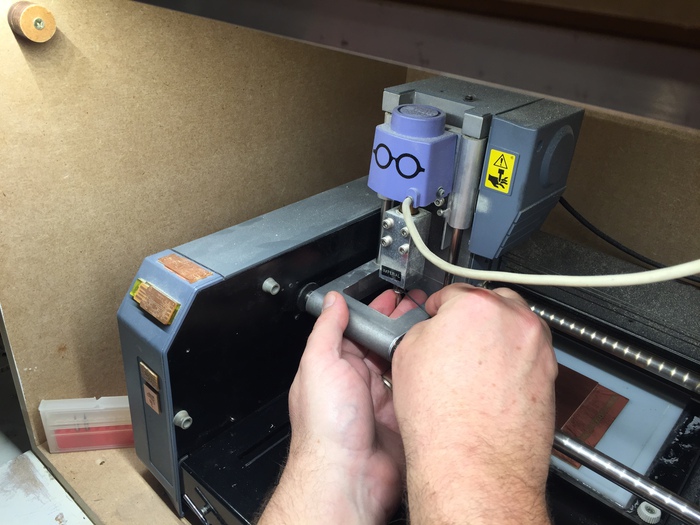
- Once here, put in a milling bit. To do so, hold the bit between ring and middle fingers with palm facing up. Push up while tightening the bit from the side with a screwdriver, using your other hand. Push the bit all the way up.
- Go back to milling machine module in mods and move to origin. This can be adjusted by sight, should be at bottom left corner of board, Usually around x: 10, y: 10
- Bring z axis all the way down using the tool commands on the machine.
- Loosen the screw by hand using the same technique used when installing the bit. Lower it until it is touching the copper. Wiggle the bit in case there is dust between it and the board.
- Rotate the file under the Read Png mod if necessary. Remember to hit Calculate again after any adjustment.
- Write down the x, y origin you are using in case your print fails and you need this information.
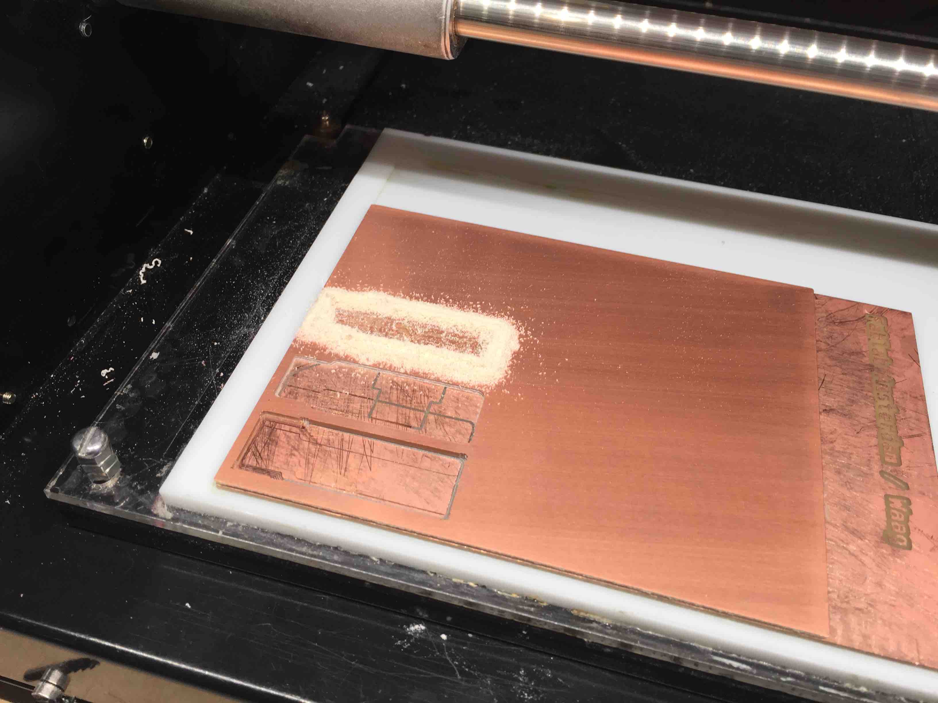
- From the websocket mod, hit send file. Milling will begin.
- When milling is complete, vacuum up the dust produced in the process. There should be a hand vacuum next to the machine.
- Now we will cut out the outline of the board. Go back to mods upload the outline file.
- In the Set PCB defaults mod, choose Mill outline
- In mill raster 2d set offset to 1. (we only need to cut it out with one line) If we hit view, we can now see that it is a 3d cut following a single path. The depth is automatically set with the mill outline default.
- At the machine mod, set speed to 4. We can move faster now as the outline does not need to be as precise.
- Change the bit in the machine to (bigger). Change it using the same method described above. Push the new bit in all the way up.
- Push the z axis all the way down. Now push it up a tiny bit, so it has enough room to go down still to cut through the board. Allow the new bit to fall gently to the plate surface.
- Go to websocket and send the file.
- Once it is done, use the screwdriver next to the board to try to move the board. If the cut was successful, it should wiggle. Push it out from the board.
- Check the board under the magnifier. Scrape off copper from the edges. Depending on the board, you may also have to remove some parts of the copper to prevent shorting. We printed a USB board, and Henk showed us how there is a small bit of copper on the end of it that needs to be removed.
Notes When cancelling a job on the Roland, make sure to hit close port, close socket on mods in addition to hitting cancel. On the mill, hold both tool up and tool down after hitting view, and you will see the light blinking. Let go after holding it down for a few seconds, then wait until you see the light stop blinking. It is now ready for a new job. You will have to hit open port open socket on mods to be able to send the machine to origin again.
Soldering
General Soldering Notes:
- Before starting, make sure you have tweezers in PERFECT condition.
- Wet the sponge on the base of the iron, touch the iron to the wire, then clean it on the sponge before you begin.
- The technique is always to touch iron to the board, add the wire, remove the wire, then remove the iron.
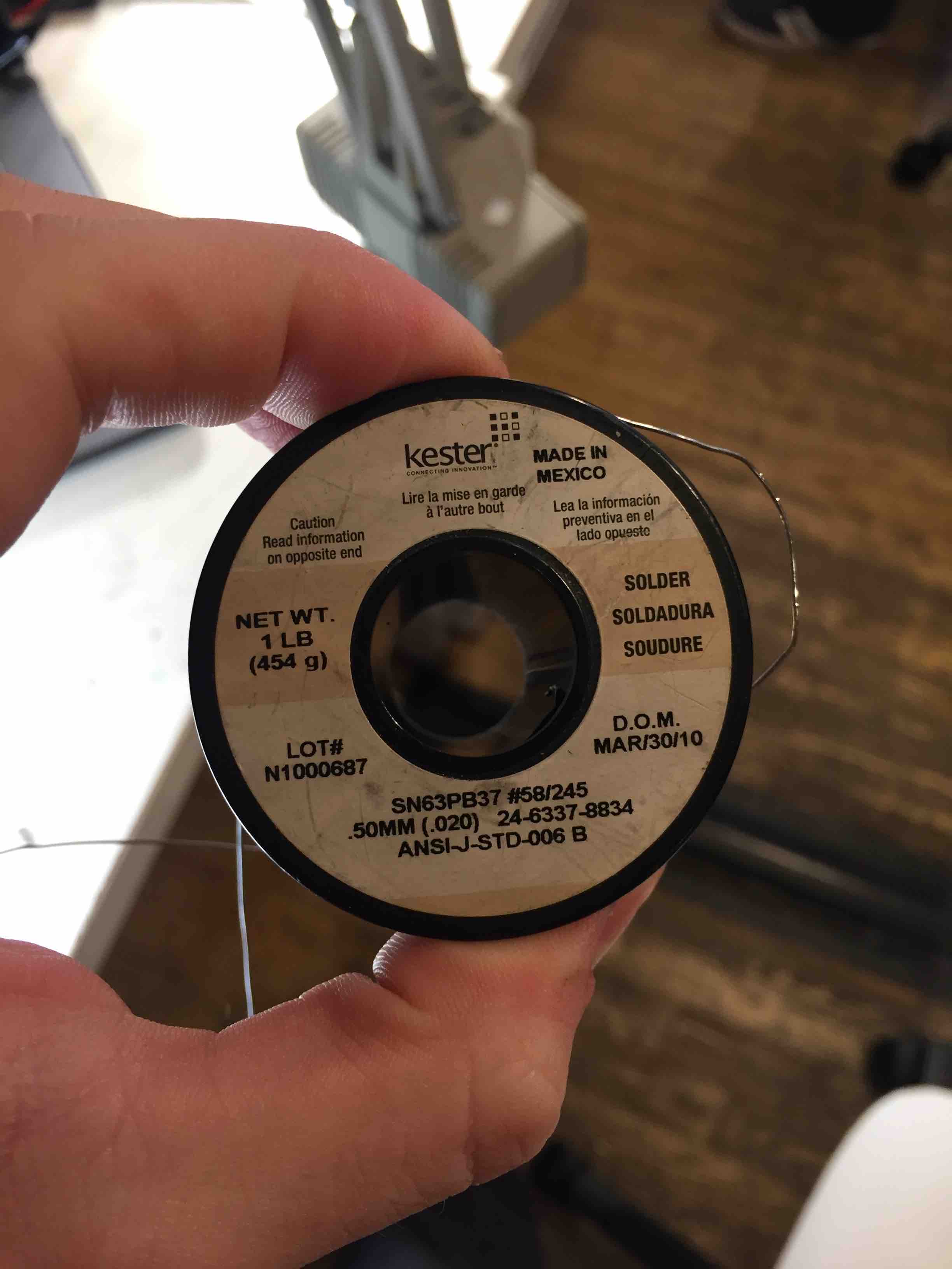
The wire we used this week:
Now, how to solder the Brian board:
- Clean the board. Solder doesn’t stick to oil. We can wash it with handsoap and water in the kitchen, and dry it with a paper towel. If it is still rough under the magnifying glass, we can “sand” it with the same paper towel.
- Place the board on a piece of office paper. It should still have double sided tape on the back. Fold the paper over and press the board into the paper so that it sticks. This way, we can move the paper when soldering and not have to touch the board itself.
- Get the iron and thin wire out. Have the guide for the “Brian” board from this week’s class link on the Fabacademy website.
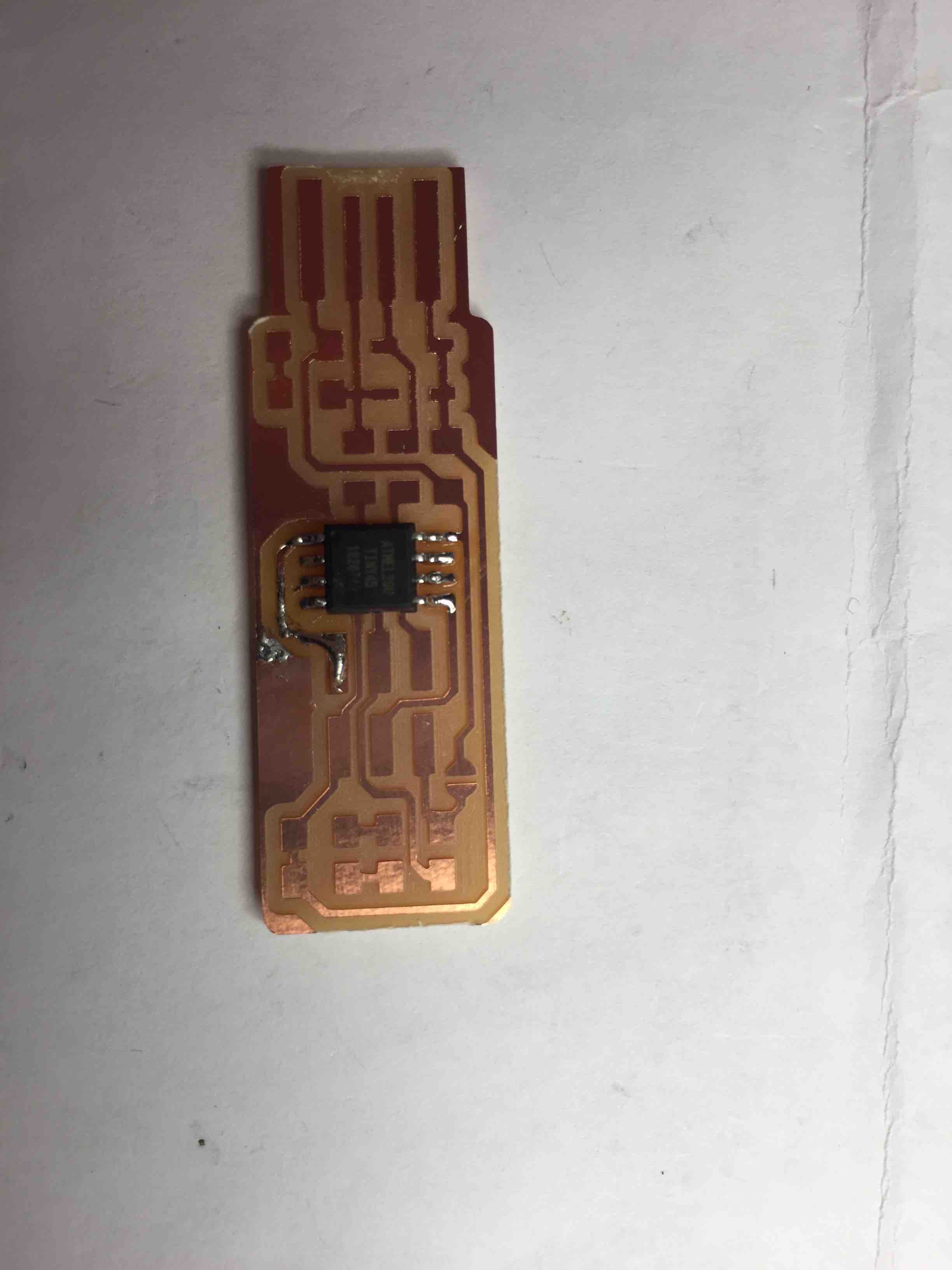
- We will attach the ATTINY45 first. It has a small black dot on Pin 1. Make sure this is positioned in the bottom left corner (ground?)
- Solder the corner with the dot first. Head the copper it will attach to, add a bit of solder there, remove the wire, remove the iron.
- Place the board down. Solder the cable coming from it to the drop of solder we have just placed on the board. Look at the other side of the ATTINY and see that all of the prongs are aligned with the copper on the board. If it is, solder the opposite corner to anchor it. Now continue to sodler around the whole chip.
- Now solder the Res 10 q. These are orientation free. For these, we put some solder down, then place the resistor on the solder. Now push down with the tweezers, and touch the iron to the solder again. Now add a drop of solder to the other side of the resistor.
- Now other reisstors. These still have no orientation, but make sure they are facing up so that the label is sbowing.
- Now Zener diodes–they have orientation.
- Now the green LED—these have green marks on one side.
- Now the ISP readers.
- Add solder to the paths at the end
- There was a blob we had to solder and desolder
Group Assignment
Complete with pictures at the above link, the steps we followed are outlined here:
-characterize the design rules for your PCB production process
For this assignment, Henk told us to mill 4 PCB boards. We would use both a one flute and 2 flute 1/8 mm drillbit, and cut a board in both climb and conventional on each bit. Hyejin downloaded the .png file from the fabacademy website.
- Hyejin attached the one flute 1/8mm drillbit to the mill by holding it the way henk had instructed us–using a flat hand with the bit between middle and ring fingers, and using the allen key with the other hand. This is the same way the bit should be held as it is removed from the machine, so as to prevent it from falling.
- Mods was already open, so we did not have to open it. Normally, the process would be to click the start-server icon on the deskto that Waag uses to load mods, then select Menu > Programs > open program > Mdx 20/PCB in the firefox window that opens.
- We imported the png file in the read file png mod.
- In set PCB defaults we chose the mill traces default. We accidentally changed the speed in this area to 1- but this is not where you change the speed! We caught the mistake and changed it in the Roland MDX mod instead.
- We went to mill raster 2d and used the default settings imported from clicking mill traces: Offset: 4 Stepover:.5 Path merge: 1 Direction: Climb Path order: Forward This means our first test will be with one flute and climb.
- We hit view in the mill raster 2d mod and we were not sure if the image showed 4 traces, even though we had set offset to 4 and we had learned that offset determines the number of traces. We set offset to 1, hit calculate, and viewed the new image. Comparing both, we could see that we did, in fact, have 4 lines the first time.
- From here, we went to the Roland MDX 20 mod and again checked that our speed was at 1.
- We went to the python websocket port and clicked open port and open socket to make sure the socket was open. Though we normally use Websocket port and not Python websocket port at Waag, we had to use the python websocket today because of connection errors.
- We discussed if we should send file or not at this point- Henk did accidentally send the file at this point in our tutorial, but Tessel had written down that after doing so he said “not yet!” We went to the machine to set the origin first.
- On the machine, we hit view. The drill and board went to their home position.
- We first brough the z axis of the head all the way down using the down tool button. We were scared to start setting x and y because it seemed possible that when we brought the bit closer to the board, it would collide with it. Hyejin thought she could push the bit higher when she had put it in, so we decided to try to push it higher to be safe.
- Back on the Roland MDX 20 mod on the computer, we started to adjust X and Y origin. We realized that the x placement of 17 from the last cut was fine, and we set y to 40. So our origin was (17,40).
- We then brought the z up a tiny bit so that the machine would have room to drill into the material, then lowered the bit to the surface of the material.
- We hit send file on the python websocket port. It started milling successfully.
- After it was done, we vacuumed up the dust and started the next board. We decided all we would have to change would be the direction and origin
- In the Roland MDX 20 mod, we changed the origin to 17,55 to move the drillbit to a fresh part of the board.
- We changed the direction to conventional in the Mill Raster 2d mod.
- We hit calculate, checked the port was open, and sent the file. Done with one flute!
- We installed the 2 flute 1/8mm bit using the method described in step 1. Note: There are two holes for the allen key on the drill head. Only one tightens/loosens the drill bit. It is easier to do this if the hole is facing out—you can turn the drillhead until it does, even if you feel some resistance.
- We set the direction to climb, changed the origin to 17, 70 and hit send file.
- We noticed that although the mill was moving, it was not actually cutting—maybe we had not lowered the bit enough.
- We hit view on the machine, cancelled the job on the computer, and tried to hold down tool up and down at the same time as Hank had instructed us to do if something went wrong. This should clear the machine’s memory. We tried to do this several times but every time we hit view again, the machine would start trying to mill the old job. Henk came over and showed us how after you hold up and down at the same time, you have to wait for the light on the machine to stop blinking. This takes much longer than expected, because the machine is running off of a microcontroller.
- After this, we hit move to origin again on the Roland MDX mod. We set the Z axis again by lowering it completely using the machine’s tool controls, raising it a tiny bit, loosening the drillbit, and lowering it until it touched the material. This time, we held down the drillbit as we tightened it to make sure it did not move up at all.
- We hit send file- it worked! We waited, and vacuumed up the dust after the machine completed the milling.
- We had to do the 4th cut in the morning and Henk had cut a board before we arrived, so we had to change the bit again. We inserted the 1/8mm 2 flute bit.
- On the computer, we hit mill traces in the settings mod, speed 1 in the Roland MDX mod, and conventional/Calculate/view in the Raster 2D mod.
- We set X and Y to 17, 85 and hit send file from the Websocket Python serial.
- Again we waited and vacuumed up the dust when we finished.
From our results it looked like both one flute and climb produced smoother lines in more detail. In order of producing results that most resembled the .png, we ranked the milling:
- One flue/climb
- One flute/conventional
- Two flute/climb
- Two flute/conventional
Weekly Assignment
make an in-circuit programmer by milling and stuffing the PCB, test it, then optionally try other PCB processes
For this week’s assignment, we had to make our own ISP. Henk recommended we start with the Brian board, the same one he worked on during the local lesson. I largely followed the steps noted above from the local lesson, I will again outline what I did here:
First, I prepared the machine.
- The base was already detached from the machine, and the sacrificial material was already bare and the tape had been cleaned.
- I grabbed the copper board I would mill and placed it face down on a towel, applying tape across the entire back
- I lined up the corner of the board with the corner of the sacrifical material. I then turned the entire base over and applied pressure to seal the new baord to the base
- I screwed the board back in
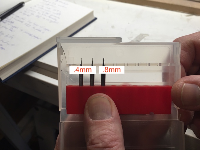
- I unscrewed th .4mm bit that was left in the machine, and replaced it with the .8mm bit
-
I pressed view to send the machine to default position
-
I downloaded the .png file on the computer that runs mods for the mill and saved it in projects/nathan
- I opened mods using the start-server icon on the desktop, and clicking Run in terminal > Menu > Programs > Open Program > Roland MDx 20/PCB
- I selected my file from the load PNG module
- In settings Mod, I chose mill traces 1/64
- In the Mill raster 2d Mod, I chose
Offset 4 Stepover.5 Direction Climb Path Merge 1 Path order Forward - I hit calculate and viewed the toolpath- all looked correct
- In the Roland MDX machine mod, I set speed to 1
- I went to the Python websocket and clicked open port, open socket
- I set X and Y of the origin to 10,10 in the machine mod and clicked send to origin. This was off, and some of the board had already been used, so I had to adjust it to 17,50.
- I adjusted the Z axis by pushing the drillbit as far up as possible and locking it in. I then lowered z all the way, and then back up a tiny bit. I let the drillbit drop until it was touching the surface of the copper.
- I hit send file in the python mod.
- It worked! Now I had to cut the outline
- I changed to the .8mm drillbit
- I downloaded the outline file to projects/nathan and loaded it into mods

- I now selected the Mill outline default. In raster 2d mod, I changed offset to 1. I changed speed to 4 in the machine mod, and hit calculate. I sent the file from the python websocket mod
- I vacuumed up the dust and put the machine in view mode. I unscrewed the plate and I tested that the board would wiggle with a screwdriver, then pried it out.
- I scraped the board off of the sacrificial board, and then scraped the tape off. I then rubbed it down with solvent, then used my hand to get the paper towel dust off.
Soldering
- Done with the machine, I had to scrape the excess copper from my board, especially the bit on the tip. I rubbed the sides with paper towel to sand it. I then washed my board, getting ready to solder.
- I placed the board on a piece of paper and it stuck from the remaining tape.
- I loaded up the guides to help me solder: Brian board. Henk said to only take out one type of component at a time so as not to lose them. He also started with the ATTiny45 in our tutorial, and finished with the 6 pin board, so I decided to do the same.
- I immediately ran into trouble soldering—I didn’t understand that I did not have to touch the wire directly to the iron, so it got a bit messy, as the wire would melt onto the iron, and I would hold the iron on the board for too long. I ended up burning off part of the copper, so I drew a new path with the solder.
- After that, the process went smoother. I figured out better soldering technique (hold the iron on the patch of copper, then touch the wire to that patch)
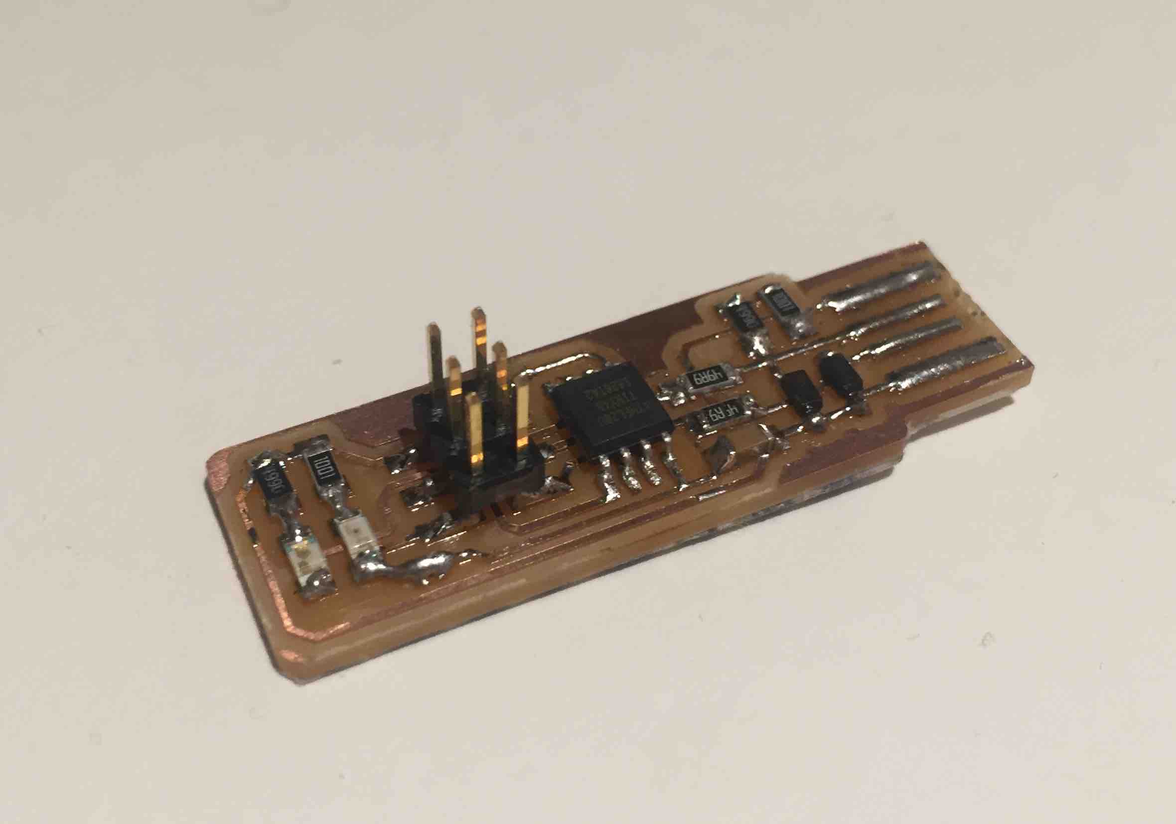
- I next attached the resistors_ first the 10ohm, then the 499, then the 49. I attached them by first placing a dot of solder where I would place them, holding the chip down on top of the solder with the tweezers, and melting it into the solder with the iron. After that, I would solder the other side.
- I next attached the zener diodes with the same method described above, making sure the line was in the right direction.
- I attached the capacitor with the same emthod described above- this had no orientation.
- i attached the Leds with the same method, making sure the cathode sides went in the right direction.
- Finally, I attached the 6 pin head, anchoring one corner then the opposite corner first, and then soldering all the other connections.
- I created the bridge where instructed to and thickened the USb contacts with some solder. I also added tape to the underside of the board to thicken it.
Programming the board
Before I got started programming myself, Hyejin tested my board on her computer- it lit up, so that was a good sign! but she couldnt run “make flash” on it. This was the same issue she was having, so she thought it might have been her computer. I was now going to try to run it on my own computer.
I followed the instructions from the Brian board site and downloaded CrossPack. I then downloaded the firmware source code. I didn’t really understand what all of this meant… so I looked at the Crosspack website and noticed that their tutorial matched the process described for building the Brian board. My understanding is that Crosspack is a development environment for the firmware for microcontrollers, and that firmware appears in a specifically formatted hierarchy of directories and files. I still did not totally understand what I was doing this week, but decided it was more important to get everything done.
I downloaded the firmware pack from the instructions, and tried to run make. However, I got the following error:
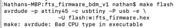 I googled this error and saw that many arduino users faced the same issue after updating to MacOSX Catalina–it was not compatible with 16bit development, only 32bit. (Dont know what this means either) As this seemed to raise a whole host of issues and I thought programming the board would be quick, I asked my friend, who was still running an earlier version of MacOS, if I could use her computer. I downloaded crosspack and the board’s firmware successfully, and ran make successfully as well. However, when I plugged in both my board and the programmer from Henk, I got the following error:
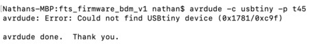
This was the same error I got on hyejin’s computer. I tried to run the command several more times, then decided to wait until I was back at Waag to work on this more.
At Waag, harm recommended I install brew tap osx-cross/avr && brew install avr-gcc to make it work on Catalina. After doing this, I was able to run make.
I also got an important tip from Henk, he instructed us to use an avrdude command which hadn’t appeared in the guide:
$ avrdude -c usbtiny -p t45

avrdude: AVR device initialized and ready to accept instructions

Reading | ################################################## | 100% 0.00s

avrdude: Device signature = 0x1e9206 (probably t45)

avrdude: safemode: Fuses OK (E:FF, H:DD, L:E1)

avrdude done.  Thank you.
This established a connection with the board we made that the machine would not establish previously, which is why we got the “could not find” error. Henk told us this tells the computer to go through the usbtiny device connected to your computer (the programmer board) and looks for a tiny45. When it finds it, the command appears successful and it shows the device, it is the one above that says (probably t45).
After Henk showed us this and my machine established a connection with my board, I think I got confused and thought I had now successfully run make flash. Because of this, I immediately ran make fuses then make rdstbl. These commands both ran successfully, so I thought I was good to go! But then… my board would not show up under USB devices when connected to my machine. Henk connected it to his Linux computer to see what came up in the dmesg dialog:
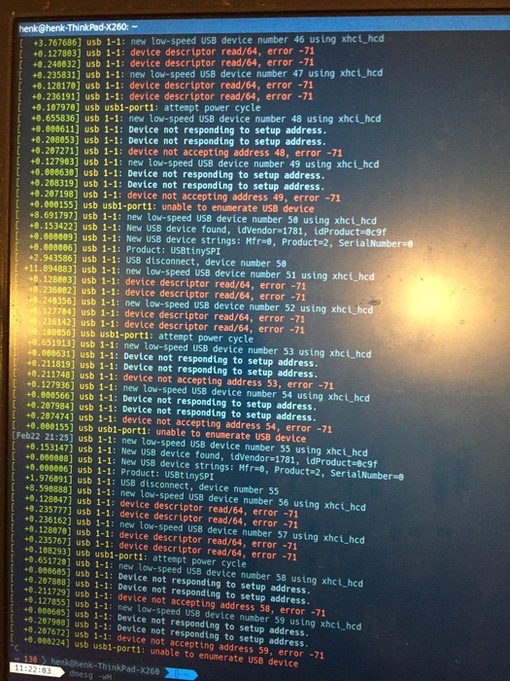
I kept getting this error. I tried adding more solder, and pressing down on each connection with the iron, but nothing helped. Then Henk asked to see my terminal window… we looked through all of my make flash commands and noticed that they all failed! I had gone straight from establishing a connection with the board to make fuses and make rdstbl. So… I had blocked my board from more programming without ever programming it. I had to replace my ATtiny
Next time, I will know what each of these commands do before I run them.
make flash installs firmware on the Attiny
make fuses creates hardware connections
Henk showed us how to remove the microcontroller with a heat gun. I soldered on a new one, repeated the process of running
avrdude -c usbtiny -p t45
make flash
make fuses
This time, I disconnected the USB and checked that it was showing up on my computer before I ran the command to close circuits. It worked!
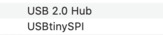
I ran make rdstbl, checked that the device still showed up, and asked Henk to check on dmesg again. All good, finally.
Then, as described in the Brian board instructions, I removed the J1 bridge in order to make the board a programmer!
Summary
This week was strange because, at the end of it, I still did not have much of an idea of what I had made or how it worked, but Henk assured us this was normal and we only needed to go through the motions of milling, programming, and debugging this week. Electronics production is a bit intimidating- both the mill and soldering are time consuming processes that can easily go wrong. Looking forward to getting a better idea of what i made this week in later electronics weeks.